


Danby DAC100ECB2GDB, DAC120EUB2GDB, DAC100EUB2GDB, DAC120ECB2GDB, DAC080ECB3GDB Owner's Use And Care Manual
...
OWNER’S USE AND CARE GUIDE
GUIDE D’UTILISATION ET D'ENTRETIEN
AIR CONDITIONER
CLIMATISEUR
02'(/02'Ê/(
DAC080ECB2GDB / DAC080EUB2GDB
DAC100ECB2GDB / DAC100EUB2GDB
DAC120ECB2GDB / DAC120EUB2GDB
DANBY PRODUCTS LIMITED, ONTARIO, CANADA N1H 6Z9
DANBY PRODUCTS INC., FINDLAY, OHIO, USA 45840
2014.12.05
1-800-263-2629
(1-800-26-DANBY)
DO NOT RETURN THIS UNIT TO THE RETAILER
WITHOUT FURTHER INSTRUCTIONS
Dear valued customer, we hope your Danby product purchase fulfills all
your requirements. Your satisfaction is our priority!
Please contact us at our toll free consumer service number for any inquiries
you may have about your new unit.
NE PAS RETOURNER CET APPAREIL CHEZ LE
DÉTAILLANT SANS CONSIGNES SUPPLÉMENTAIRES
Cher(ère) client(e) important(e), nous espérons que votre produit Danby
répond à tous vos besoins. Votre satisfaction est notre priorité!
Veuillez nous contacter au numéro gratuit de service après-vente, si
vous avez des questions quelconques à propos de votre nouvel appareil.
NO DEVUELVA ESTA UNIDAD A LA TIENDA SIN
INSTRUCCIONES ADICIONALES
Estimado cliente, esperamos que el producto Danby que ha comprado
satisfaga completamente sus necesidades. Su satisfacción
es nuestra prioridad!
Por favor, contáctenos gratuitamente a nuestro número de Servicio al
Cliente para cualquier pregunta que tenga sobre su nuevo electrodoméstico.
Danby 28.08.2014

TO OBTAIN WARRANTY SERVICE YOU MUST PROVIDE A VALID PROOF OF
PURCHASE. PLEASE STAPLE YOUR RECEIPT TO THIS PAGE FOR FUTURE
REFERENCE.
_____________________________________________________________________
POUR OBTENIR LE SERVICE SUR GARANTIE, VOUS DEVEZ FOURNIR UNE
PREUVE D’ACHAT VALIDE. VEUILLEZ AGRAFER VOTRE REÇU À CETTE PAGE
POUR RÉFÉRENCE FUTURE.
_____________________________________________________________________
IMPORTANT - GROUNDING METHOD
This product is factory equipped with a power supply cord that has a three-pronged grounded plug. It must
be plugged into a mating grounding type receptacle in accordance with the National Electrical Code and
applicable local codes and ordinances. If the circuit does not have a grounding type receptacle, it is the
responsibility and obligation of the customer to exchange the existing receptacle in accordance with the
National Electrical Code and applicable local codes and ordinances. The third ground prong should not,
under any circumstances, be cut or removed. Never use the cord, the plug or the appliance when they show
any sign of damage. Do not use your appliance with an extension cord unless it has been checked and tested by a qualifi ed electrician or electrical supplier.
IMPORTANT - MÉTHODE POUR LA MISE À LA TERRE
Ce produit arrive d’origine avec un cordon d’alimentation équipé d’une prise à trois fi ches. Il doit être
branché dans une prise avec une fi che de mise à la terre en conformité avec le Code national de l’électricité
et les codes et règles locaux applicables. Si la prise murale n’a pas de mise à la terre, il est de la
responsabilité et l’obligation du client de changer la prise existante pour la rendre conforme au Code
national de l’électricité et aux codes et règles locaux applicables. La fi che de mise à la terre ne doit pas, en
aucune circonstance, être coupée ou retirée. Si vous apercevez des signes de dommage, n’utilisez jamais le
cordon d’alimentation, la prise ou l’appareil. N’utilisez jamais l’appareil avec une rallonge sauf si elle a été
vérifi ée et testée par un électricien qualifi é ou un fournisseur de matériel électrique.
CONTENTS
TABLE DES MATIÈRES
AIR CONDITIONER
Owner’s Use and Care Guide ................................1-17
• Welcome
• Important Safety Information
• Features
• Installation Instructions
• Operation Instructions
• Care and Maintenance
• Troubleshooting
• Warranty
CAUTION:
Read and follow all safety rules and operating
instructions before fi rst use of this product.
AVERTISSEMENT :
CLIMATISEUR
Guide d’utilisation et d’entretien............................18-34
• Bienvenue
• Consignes de sécurité importantes
• Caractéristiques
• Consignes d’installation
• Consignes d’utilisation
• Soins et entretien
• Dépannage
• Garantie
Veuillez lire attentivement les consignes de
sécurité et les instructions d’utilisation avant
l’utilisation initiale de ce produit.
DAC080ECB2GDB / DAC080EUB2GDB / DAC100ECB2GDB
DAC100EUB2GDB / DAC120ECB2GDB / DAC120EUB2GDB
Model • Modèle

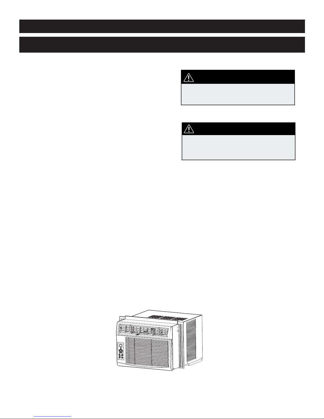
WELCOME
Welcome to the Danby family. We are proud of our quality products, and we believe in dependable service, like you will
fi nd in this Owner’s Use and Care Guide, and like you will receive from our friendly customer service department. Best of
all, you will experience these values each and every time you use your Danby appliance. That is important, because your
new appliance will be a part of your family for a long time.
For easy reference, we suggest you attach a copy of your sales slip/receipt to this page, along with the following
information, located on the manufacturer’s nameplate on the right side of the unit above the powercord.
Note the information below; you will need this information to obtain service under warranty.
To receive service, you must provide the original receipt.
NOTE: THIS UNIT IS NOT DESIGNED FOR “THROUGH-THE-WALL” INSTALLATION.
Model No:
Serial No:
Date Purchased:
NEED HELP?
Before you call for service, here are a few things you can do to
help us serve you better:
Read this Owner’s Use and Care Guide:
It contains instructions to help you use and maintain your
appliance properly.
If you received a damaged appliance:
Immediately contact the retailer (or builder) that sold you the
appliance.
Save time and money:
Check the Troubleshooting section at the end of the guide
before calling. This section helps you solve common problems
that may occur.
If you do need service, you can relax, knowing help is only a
phone call away.
1-800-26-
(1-800-263-2629)
WARNING
Improper connection of the grounding plug can result in risk of
fi re, electric shock and/or injury to persons associated with the
appliance. Check with a qualifi ed service representative if in doubt
that the appliance is properly grounded.
1
Important Safety Information
READ AND FOLLOW ALL SAFETY INSTRUCTIONS
FOR YOUR SAFETY : Read these instructions carefully before operating the unit.
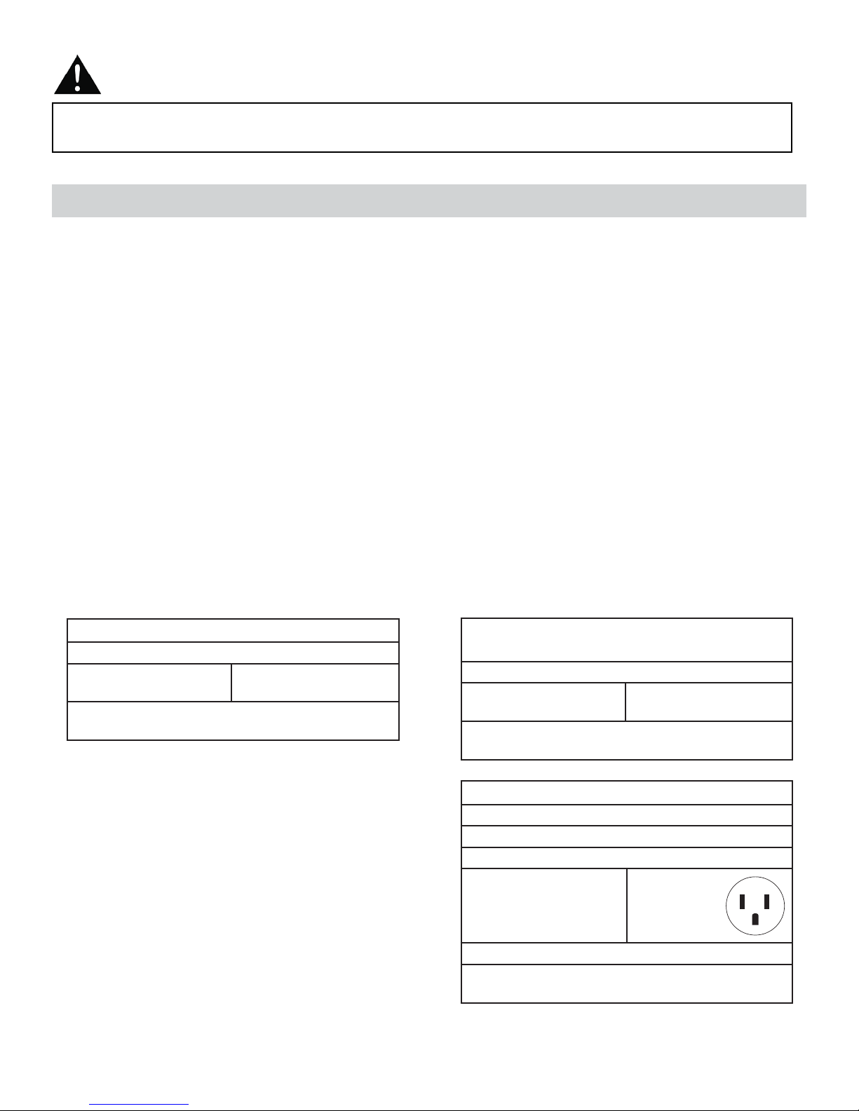
ELECTRICAL SPECIFICATIONS
1. All wiring must comply with local and national electrical codes and must be installed by a qualifi ed electrician. If you
have any questions regarding the following instructions, contact a qualifi ed electrician.
2. Check available power supply and resolve any wiring problems BEFORE installing and operating this unit.
3. This 115V air conditioner uses 9.4 or less nameplate amps and may be used in any properly wired, general-purpose
household receptacle. See Table 1 for the specifi cations for the individual branch circuit.
4. For your safety and protection, this unit is grounded through the powercord plug when plugged into a matching wall
outlet. If you are not sure whether your wall outlet is properly grounded, please consult a qualifi ed electrician.
5. The wall outlet must match the 3-prong plug on the service cord supplied with the unit. DO NOT use plug adapters.
See Table 2 for receptacle and fuse information.
6. The rating plate on the unit contains electrical and other technical data. The rating plate is located on the right side of
the unit, above the powercord.
TABLE 1 DAC080EC/UB2GDB
Suggested Individual Branch Circuit
Nameplate Amps
6.2
AWG- American Wire Gauge
*Based on copper wire at 60°C temperature rating
*AWG Wire Size
16
TABLE 1 DAC100EC/UB2GDB
DAC120EC/UB2GDB
Suggested Individual Branch Circuit
Nameplate Amps
7.8 to 9.4
AWG- American Wire Gauge
*Based on copper wire at 60°C temperature rating
*AWG Wire Size
14
TABLE 2
Receptacle and Fuse Types
Rated Volts 125
Amps 15
Wall Outlet
Fuse Size 15
Time Delay Fuse Plug Type
(or Circuit Breaker)
2

Important Safety Information
r
READ AND FOLLOW ALL SAFETY INSTRUCTIONS
FOR YOUR SAFETY : Read these instructions carefully before operating the unit.
ENERGY SAVING TIPS
Your appliance is designed to be highly effi cient in energy savings. Follow these recommendations for greater effi -
ciency.
1. Select a thermostat setting that suits your comfort needs and leave at that chosen setting.
2. The air fi lter is very effi cient in removing airborne particles. Keep the air fi lter clean at all times (usually cleaned every
2 weeks depending on indoor air quality).
3. Use drapes, curtains or shades to keep direct sunlight from penetrating and heating the room, but do not allow drapes
or curtains to obstruct the air fl ow around the unit.
4. Start your air conditioner before the outdoor air becomes hot, to avoid an initial period of discomfort while the unit is
cooling the room.
5. When outdoor temperatures are cool enough, use the FAN MODE only, on HIGH, MED., or LOW setting. This
circulates indoor air, providing some cooling comfort, and utilizes less electricity than operating on a cooling setting.
FEATURES
*Fresh Air Ventilation Switch
(open for Fan only operation,
available in some models
only)
Interior Air Outlet
Control Panel
Interior Air Inlet
Cabinet
Exterior
Air Inlet
Air Filte
*Pushed in, means the vent is closed.
Pulled out, means the vent is open.
3

INSTALLATION INSTRUCTIONS
ELECTRIC SHOCK HAZARD
NOTE: Your Room Air Conditioner is designed for easy
installation in a single or double-hung window. This unit
To avoid the possibility of personal
injury, disconnect power to the unit
is NOTdesigned for vertical (slider type) windows and/or
through-the-wall applications.
before installing or servicing.
TOOLS NEEDED FOR INSTALLATION:
• Screwdrivers: Phillips and fl at head.
• Power Drill: 1/8in. (3.2mm) diameter drill bit
• Pencil
• Measuring Tape
• Scissors
• Carpenter’s Level
NOTE: Save the shipping carton and packing materials for future storage or transportation. From
the carton, remove the plastic bag containing the installation hardware kit necessary for the installation of your air conditioner. Please check the contents of the hardware kit against the corresponding model check list, prior to installation of the unit. See Fig. 1.
CAUTION
Because the compressor is located on the controls side of the unit (left side), this side
will be heavier and more awkward to manipulate. Inadequate support on the control side
of the unit can result in personal injury and damage to your unit and property. Therefore,
it is recommended that you have someone assist you during the installation of this unit.
INSTALLATION
HARDWARE
Fig. 1
Regular
Foam Seal(1)
1/2in. (13 mm)
screws (7)
3/8in. (9.5mm) screws
(4) *Factory installed
on some models
Adhesive
Foam Seal(1)
Side Curtain RH (1)
Side Curtain LH (1)
Safety Lock (1)
“L” Shaped
mounting
bracket (1)
* Factory installed
on some models
Sash bracket (2)
4

INSTALLATION INSTRUCTIONS
LOCATION
1. This room air conditioner is designed to fi t easily into a single or double hung window. However, since window designs
vary, it may be necessary to make some modifi cations for safe, proper installation.
2. Make sure window and frame are structurally sound and free from dry and rotted wood.
3. For maximum effi ciency, install the air conditioner on a side of the house or building which favours more shade than
sunlight. If the unit is in direct sunlight, it is advisable to provide an awning over the unit.
4. Provide suffi cient clearance around the cabinet to allow for ample air circulation through the unit (See Fig. 2). The
rear of the unit should be outdoors. It should not be in a garage, or inside a building. Keep unit as far away as possible from obstacles/obstructions and at least 30 in. (76 cm) above the fl oor or ground. Curtains and other objects within
the room should be prevented from blocking the air fl ow.
5. Be certain that the proper electrical outlet is within reach of the installation. Use only a single outlet circuit rated at 15
amps. All wiring should be in accordance with local and national electrical codes.
6. DO NOT install unit where leakage of combustible gas is suspected. Your air conditioner may fail to operate in air
containing oils (including machine oils), sulfi de gas, near hot springs, etc.
NOTE: Your unit is designed to evaporate condensation under normal conditions. However, under extreme humidity conditions, excess condensation may cause basepan to overfl ow to the outside. The unit should be installed where conden-
sation run-off cannot drip on pedestrians or neighbouring properties.
NOTE: It is normal for your unit to drip a small amount of water, especially on excessively humid days.
Fig. 2
20 in.
(50.8 cm)
Min
Side
Obstruction
Ground
12 in. (30.5 cm) Min
30 in. (76.2 cm)
Min
Awning
20 in.
(50.8 cm)
Min
Fence,
wall, or
other
obstacle
5

INSTALLATION INSTRUCTIONS
ASSEMBLY AND INST ALLATION
1. Assembly of the upper channel to the cabinet (factory installed on some units).
• “L” Shaped Top Channel: install the “L” shaped channel to the top of the cabinet as shown in Fig. 3, using four (4)
3/8 in. (9.5 mm) screws.
2. Assembly of the side curtains to the cabinet.
• Extend the shutter from the shutter frame and slide it into the shutter tabs on the side channel of the air conditioner,
as shown in Fig. 4.
• Slide the shutters into the top (“L” shaped) and bottom (“U” shaped) channels. The shutters are identifi ed (on frame)
as left and right.
Slide down into tabs
Fig. 3
3/8 in. (9.5 mm)
“L” shaped mounting
bracket
Fig. 4
“U” shaped Channel
(Factory Installed)
Shutter tabs
Shutter
Shutter frame
3. Completing the installation.
• Cut the foam (non adhesive) sealing strip to fi t the area of the window sill that the air conditioner will rest on.
• Carefully place the air conditioner into the window with the “L” shaped mounting bracket (on top) positioned in front
of the upper window sash. The bottom of the cabinet should be positioned on the “recessed” portion of the window
frame. Pull the window down until it rests just behind the front fl ange of the (top) “L” shaped mounting bracket (See
Fig. 5).
• Expand the shutter frames (fully) on each side and secure the top of the frames to the window sash using one 1/2 in.
(13 mm) screw on each side and one in the “L” shaped mounting bracket (Fig. 5).
• Secure the shutter clamp on each side of the lower part of the shutter, and secure to window sill using one 1/2 in.
(13 mm) screw on each side (Fig. 5).
• Place the second foam sealing strip to fi t the opening between the inside and outside windows, then attach the safety
lock to the outside window frame using one 1/2 in. (13 mm) screw (See Fig. 6).
PLEASE NOTE: Window applications come in a variety of different styles. Therefore, it may be necessary to modify your
particular installation.
Window sash
Fig. 6Fig. 5
1/2 in. (13mm) screws
Safety Lock
Foam Seal
(adhesive)
Shutter clamps
“L” Shaped
Mounting
Bracket
1/2 in. (13 mm) screw
6

INSTALLATION INSTRUCTIONS
ASSEMBLY AND INSTALLATION (cont’d)
Check that the air conditioner is tilted downwards to the outside, about 3° to 4°, as shown in Fig. 7. After proper installation, condensed water should not drain from the overfl ow drain hole during normal use. If you notice water leaking out,
check the angle of tilt, and make any necessary adjustments. However, on a very humid day, water leakage can occur –
this is normal.
Note: To achieve 3° to 4°, you must measure the H, see fi gure 7.
Measure the tilt angle from the cabinet’s edge. The distance H should be approximately 3/4 in. to 1 in. (19 mm - 2.5 cm)
for DAC080ECB2GDB and DAC080BUB2GDB. The distance H should be approximately 1 in. to 1 3/8 in. (2.5 cm - 3.5
cm) for DAC100ECB2GDB, DAC100EUB2GDB
Fig. 7
, DAC120ECB2GDB and DAC120EUB2GDB.
Measure the tilt angle from the cabinet’s edge
WINDOW
: approximately 3/4 in. (19 mm) to
1 in. (2.5 cm) for
: approximately 1 in. (2.5 cm) to
1 3/8 in. (3.5 cm) for
DAC080EB2GDB
DAC110EB2GDB
DAC120EB2GDB
OPERATING INSTRUCTIONS
KEY PAD FEATURES
Temp / Timer
Control
68
Check
Filter
Auto
MODE
Mode
Selector
Auto
LED
Display
Auto
Timer
Sleep
Mode
Fan
Speed
LED DISPLAY: Displays the following information independently - Set Temperature, Ambient RoomTemperature
and Auto Timer On/Off settings.
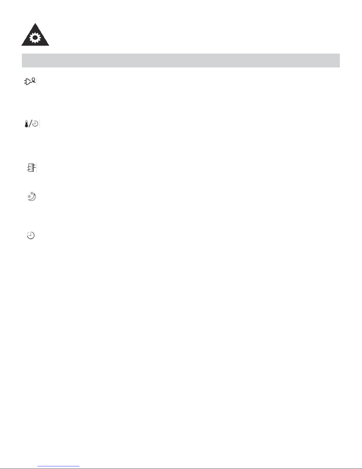
POWER: Turns unit On/Off.
MODE: Allows you to scroll through and select the desired
operating mode: Cool, Dry, Fan Only and *Auto. The selected mode will be denoted by the adjacent indicator light.
*Auto mode is a pre-set factory program that automatically defi nes the mode (Cool or Dry) and fan speed, based
on the set temperature. The unit will automatically launch
the Energy Saver function when it is in Cool, Dry, or Auto
modes.
FAN SPEED: Select from four different fan settings: Low,
Medium, High and Auto during Cool and Fan Only mode.
Please note, during Dry mode the fan speed is automatically defi ned.
Energy
Saver
Power
Button
7
OPERATING INSTRUCTIONS
KEY PAD FEATURES (cont’d)
ENERGY SAVER: Automatically cycles the fan on and off while the compressor is not in use. This function
is available in Cool, Dry, and Auto modes (only Auto-Cool and Auto-Fan modes). The fan will continue to run
for 3 minutes after the compressor shuts off. The fan then cycles on for 2 minutes at 10 minute intervals,until
the room temperature is above the set temperature. At this point, the compressor turns back on and cooling
restarts.
TEMP / TIMER CONTROL: Used to increase or decrease the Temperature setting in 1°C / 1°F increments,
and Auto-Timer On/Off settings in 30min./1hr. increments. Note: This appliance allows you to select the
temperature scale to be displayed in either “Celsius” or “Fahrenheit” according to your preference.To change
the temperature scale displayed on the electronic display, press both the “Temp/Timer” adjust arrows simultaneously to alternate between Celsius and Fahrenheit.
CHECK FILTER: The adjacent indicator light will illuminate as a reminder to clean the air conditioner fi lter
(see page 11). Once the fi lter has been cleaned and replaced, depress the Check Filter button in order to
resume operation.
SLEEP MODE: In this mode, the selected temperature will increase (when in cooling mode) by 1°C/2°F
one half-hour after Sleep mode has been selected. The temperature will then increase by another 1°C/2°F
after an additional half hour. This new temperature will be maintained for 6 hours before returning to the
originally selected temperature. This ends the Sleep mode and the unit will continue to operate as originally
programmed. The Sleep mode program can be cancelled at any time during operation by pressing the Sleep
button again.
AUTO-TIMER: Used to initiate the Auto On/ Auto Off timer.
When the air conditioner is off (Auto-On feature):
1) Press the Auto-Timer button once and the adjacent Auto-On indicator light will illuminate.
2) Use the Temp/Timer control cursors to select a delayed ON time of up to 24 hours.
3) Select the appropriate mode under which you want the unit to operate (Auto-Cool-Dry-Fan Only).
4) Select the fan speed setting.
5) The time you selected will appear in the LED display.
When the air conditioner is on (Auto-Off feature):
1) Press the Auto-Timer button twice and the adjacent Auto-Off indicator light will illuminate.
2) Use the Temp/Timer control cursors to select a delayed OFF time of up to 24 hours.
3) The time you selected will appear in the LED display. The Auto-On and Auto-Off timer features can operate
during the same program by defi ning the Auto-Off parameters immediately after the Auto-On parameters.The
Auto-Timer may be cancelled at any time by turning the unit On/Off.
For example, if you want to turn the unit on one hour later, to operate for one hour and then stop, set Auto-On
“1” and Auto-Off “2”.
Note: This is a “one-shot” timer. It does not continue to cycle on and off. It will turn the unit on (if set by the
user) ONE time. It will turn the unit off (if set by the user) ONE time. If you require the unit to turn on/off again
automatically, then you must set the timer again.
8
 Loading...