


Venus 1500
Daktronics Venus® 1500 Controlled signs with Hy-Tek & FinishLynx Quick Guide 1
NOTE: This reference is intended as a guide to help configure Venus 1500
controlled signs to interface with Hy-Tek’s MEET MANAGER for track and
FinishLynx photo finish system. A software key is required to use
Venus 1500 Real Time. See ED-14511 for Hy-Tek and FinishLynx settings and
configurations.
Figure 1: V1500 Shell
Venus 1500 Real Time with Hy-Tek
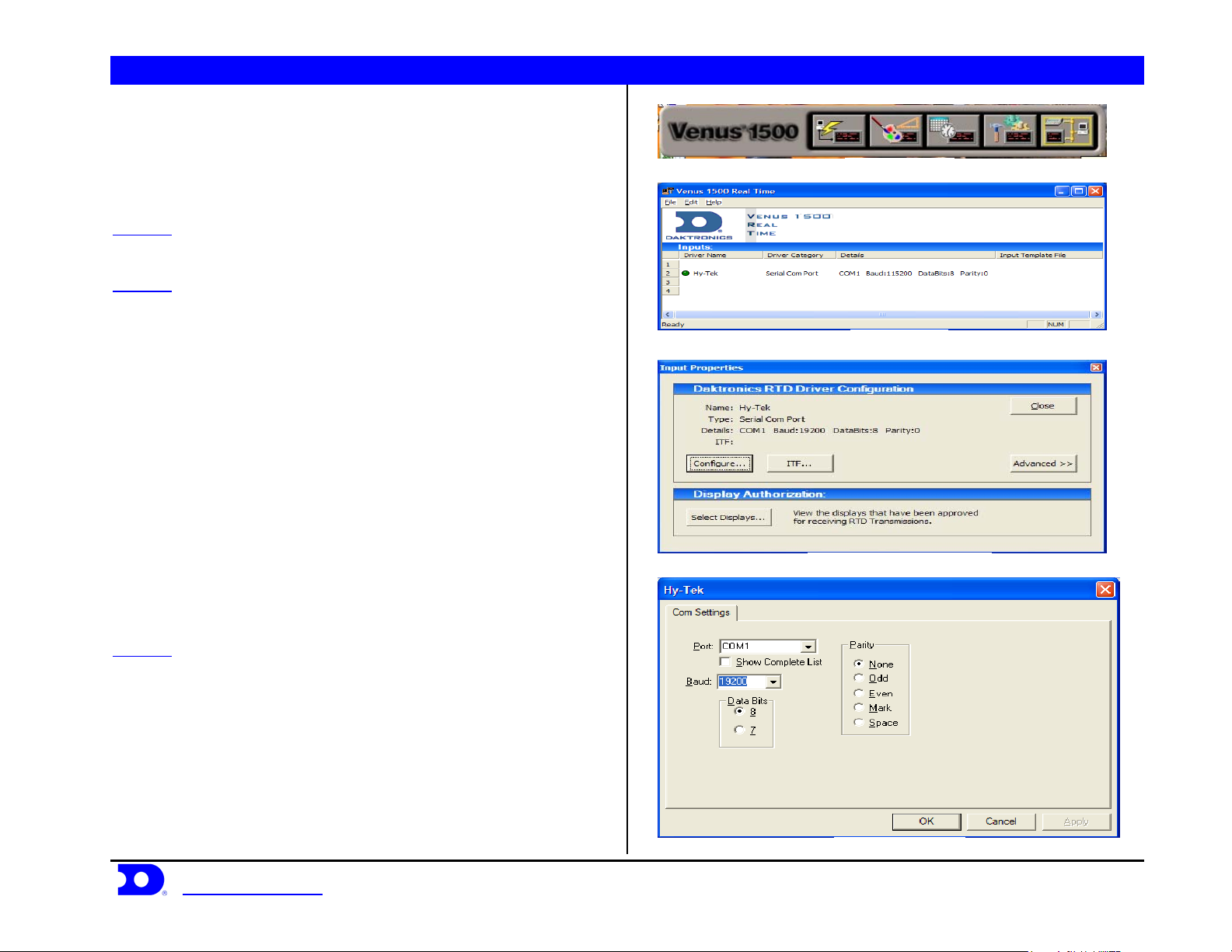
STEP 1: Connect a 9pin female to 9pin female null modem cable
from the Hy-Tek computer to the Venus 1500 computer.
STEP 2: Create an input for V1500 Real Time; to do this open
V1500 Real Time by clicking the V1500 Real Time button on the
V1500 shell shown in Figure 1. Right click on Input 2 on the screen
shown in Figure 2, and select New. Select Configure from the box
shown in Figure 3. In configuration select Serial Com Port, name it
Figure 2: V1500 RT
Hy-Tek, and press OK. Select the Com Port number that the 9pin
cable is plugged into on the V1500 machine, as the port number.
Baud Rate: 19200, Data Bits: 8, Parity: None. An example is shown in
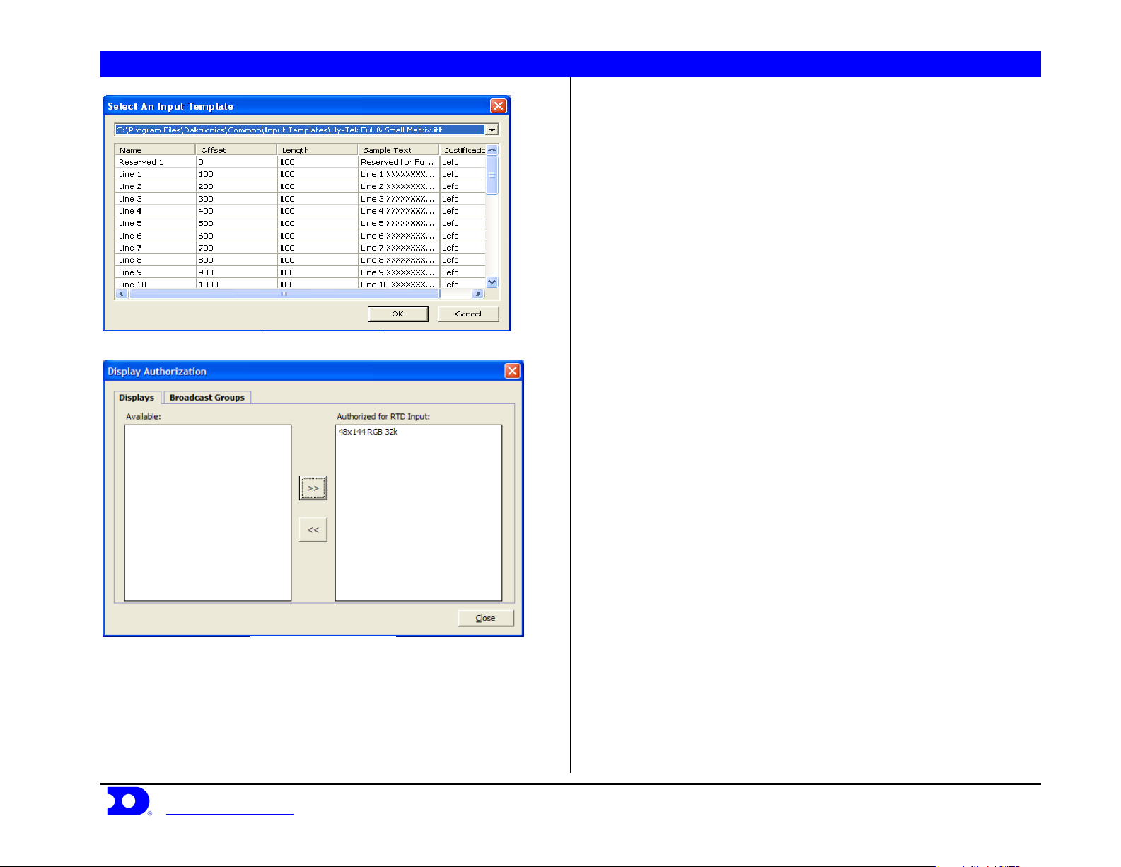
Figure 4. Press ITF on the screen in Figure 3. Click on the Down
Arrow in the upper right corner of the screen and select Browse look
in: C:\Program Files\Daktronics\Common\Input Templates\ and select
the Hy-Tek Full & Small Matrix.itf shown in Figure 5. If this file does
not show up on the list, it will need to be copied into the directory.
When complete the screen should look like Figure 5. Press Ok to
continue. Press Select Displays on the screen in Figure 3. Select the
display that the Hy-Tek data will be going to and press the Arrow to
Figure 3: Input Properties V1500 RT
move it into the column labeled Authorized for RTD Input, shown in
Figure 6, then press Close.
STEP 3: Test communication by sending data from Hy-Tek and
watch the green circle next to the input name shown in Figure 2. If it
blinks on and off, V1500 Real Time is receiving information from
Hy-Tek.
Daktronics, Inc. © 2007 P.O. Box 5128, 331 32
www.daktronics.com tel (605) 697-4036 or (877) 697-1115 fax (605) 697-4444
nd
Ave Brookings, SD 57006 ED17910-Rev 1 P1153
Figure 4: Com Port Setup
Daktronics Venus® 1500 Controlled signs with Hy-Tek & FinishLynx Quick Guide 2
Figure 5: Input Template
Figure 6: Display Authorization
Daktronics, Inc. © 2007 P.O. Box 5128, 331 32
www.daktronics.com tel (605) 697-4036 or (877) 697-1115 fax (605) 697-4444
nd
Ave Brookings, SD 57006 ED17910-Rev 1 P1153
Daktronics Venus® 1500 Controlled signs with Hy-Tek & FinishLynx Quick Guide 3
Venus 1500 Controlled Display with
FinishLynk via Ethernet
STEP 1: Add the V1500 computer to the network already consisting
of the FinishLynx Computer, EtherLynx camera and Galaxy display.
All components must be in the same subnet/IP Range, and Subnet
mask (255.255.255.0). The recommended addressing scheme is shown
is Figure 7.
Component IP Address
Finish Lynx Capture Computer 1 192.168.0.5
FinishLynx Capture Computer 2 192.168.0.15
Finish Lynx Edit Computer 192.168.0.25
Venus 1500 Computer 192.168.0.50
Track Scoreboards 192.168.0.51 – 192.168.0.54
Field Scoreboards 192.168.0.55 – 192.168.0.64
Hy-Tek Computers 192.168.0.90 – 192.168.0.94
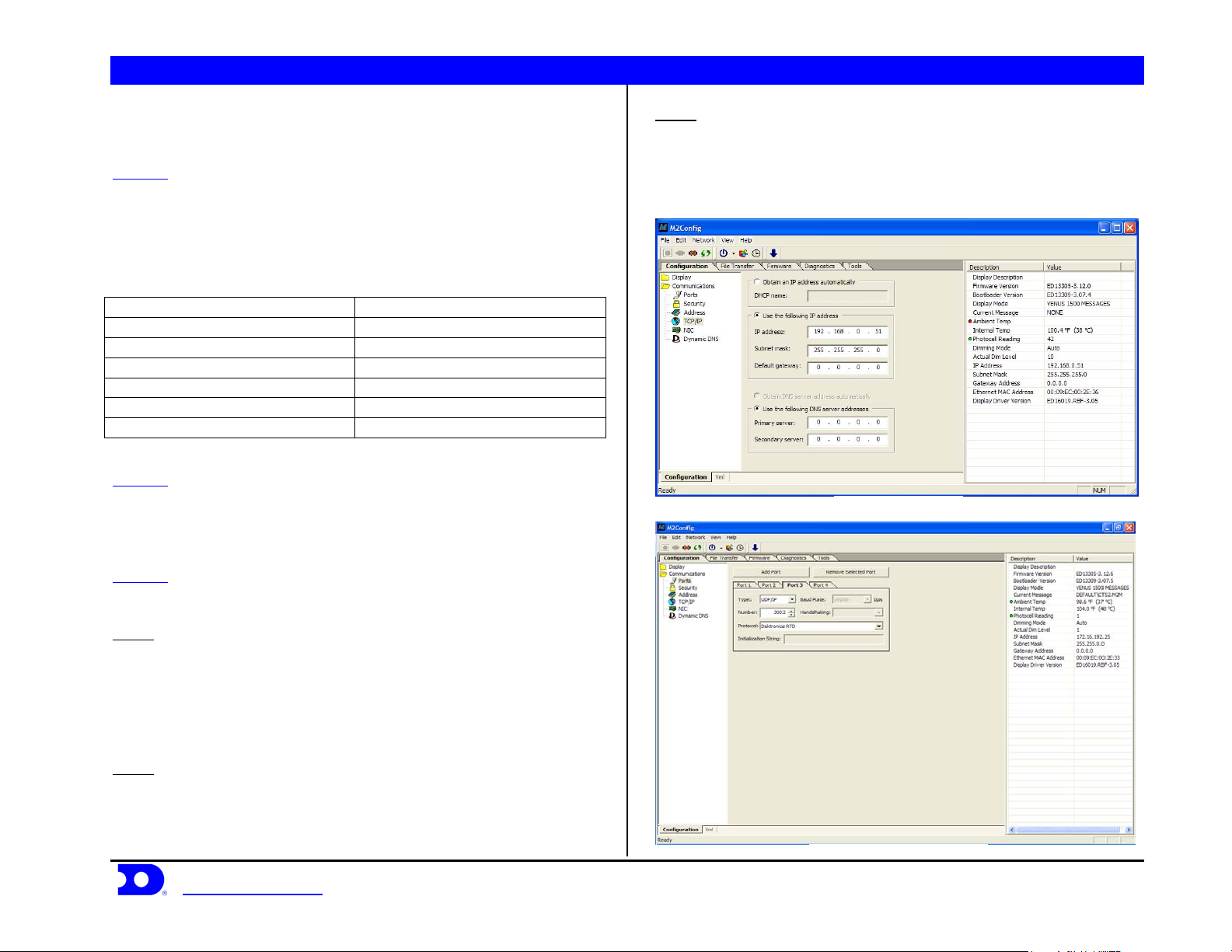
STEP 2: Using the M2Config program connect to the sign and change
the IP address within the range shown in Figure 8. This setting is
located under the communications folder and TCP/IP, which is
shown in Figure 8.
STEP 3: While connected to the sign, verify that Port 1-3 are set up as
follows:
Port 1
Type: Direct
Baud Rate: (19,200 for Galaxy Displays)
(115,200 for Galaxy Pro Displays)
Number: 1
Protocol: Venus 1500
Port 2
Type: TCP/IP
Number: 3001
Protocol: Venus 1500
Daktronics, Inc. © 2007 P.O. Box 5128, 331 32
www.daktronics.com tel (605) 697-4036 or (877) 697-1115 fax (605) 697-4444
Figure 7: Network Addressing
Port 3
Type: UDP/IP
Number: 3002
Protocol: Daktronics RTD
An example is shown in Figure 9.
Figure 8: TCP/IP settings
nd
Ave Brookings, SD 57006 ED17910-Rev 1 P1153
Figure 9: M2Config – Port Settings
 Loading...