


Daktronics Venus® 7000 Controller Track Setup Guide
NOTE: This reference is intended as a guide to help configure the Venus 7000 controller to interface with Hy-Tek’s MEET MANAGER for track and FinishLynx photo finish system.
STEP 1 Configure RTD Inputs
Click on <Configure> shown in Figure 1. Next, select the RTD Inputs file tab as seen in Figure 2. To edit an input, highlight a number (i.e. 1:) and click on <Edit Input>.
Figure 2: RTD Inputs
Figure 1: Venus 7000 Shell Menu
STEP 2 Configure RTD Input 1
Choose Input 1 and configure it per Figure 3 for a serial connection from Hy-Tek’s MEET MANAGER.
Figure 3: RTD Input 1 settings for a serial connection from the MEET MANAGER
Venus® is a registered trademark of Daktronics, Inc. |
FinishLynx™ is a trademark of the Lynx System Developers, Inc. |
|
Windows® and DOS® are registered trademarks of Microsoft, Inc. |
Hy-Tek Meet Manager® is a registered trademark of Hy-Tek ltd. |
|
Daktronics, Inc. |
PO Box 5128, 331 32nd Ave. Brooking, SD 57006 |
ED-12636 REV 1 |
www.daktronics.com |
tel (605) 697-4036 or (877) 697-1115 fax (605) 697-4444 |
e-mail: helpdesk@daktronics.com |
|
|
Page 1 of 10 |
Daktronics Track Venus® 7000 Controller COM Port Troubleshooting Guide
STEP 3 Identify how FinishLynx will connect to the Venus 7000. Option 1 is through a serial comm. port. Option 2 is over the network via a UDP/IP socket. One thing to consider when making this decision is that if you use serial ports and you want to send both results and running time from the FinishLynx capture computer, it is best to use two separate scoreboard outputs. If you use serial ports, then you need two serial ports. If you use the network, you just need to configure two UDP/IP scoreboard outputs, but no further hardware is required. If you decide to use the network, you will need the NCP plug-in from FinishLynx. It is possible to send both run time and results on the same serial port, but while the run time is counting on the scoreboard, there will be no results sent over. Either stop the run time manually, or by using the internal photocell in FinishLynx. After you have stopped the run time, when the next result is picked, it will be sent to the scoreboard.
STEP 4 Configure RTD Inputs 2, 3 & 4.
Input 2 will be the running time from FinishLynx Capture computer. Input 3 will be the start lists and results from FinishLynx Capture computer and Input 4 will be the start lists and results from FinishLynx Edit Computer.
Serial Port Connection
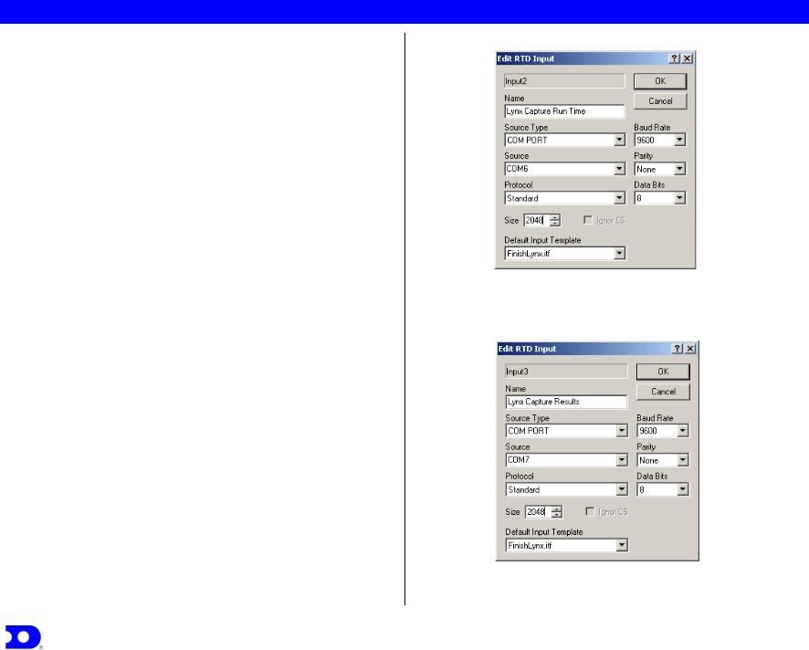
Choose Input 2 and configure it per Figure 4. Choose Input 3 and configure it per Figure 5. Choose Input 4 and configure it per Figure 6.
OR
Network via a UDP/IP socket connection
Choose Input 2 and configure it per Figure 7. Choose Input 3 and configure it per Figure 8. Choose Input 4 and configure it per Figure 9.
Figure 4: RTD Input 2 Settings for Run Time from a serial comm. port on the Lynx Capture Station.
Figure 5: RTD Input 3 Settings for Results from a serial comm. port on the Lynx Capture System.
Daktronics, Inc. |
PO Box 5128, 331 32nd Ave. Brooking, SD 57006 |
ED-12636 REV 1 |
www.daktronics.com |
tel (605) 697-4036 or (877) 697-1115 fax (605) 697-4444 |
e-mail: helpdesk@daktronics.com |
|
|
Page 2 of 10 |

Daktronics Track Venus® 7000 Controller COM Port Troubleshooting Guide
Figure 6: RTD Input 4 Settings for Results from a serial comm. port on the Lynx Edit Station.
Figure 7: RTD Input 2 Settings for Run Time over a UDP/IP network socket from the Lynx Capture Station.
Figure 8: RTD Input 3 Settings for Results over a UDP/IP network socket from the Lynx Capture Station.
Figure 9: RTD Input 4 Settings for Results over a UDP/IP network socket from the Lynx Edit Station.
Daktronics, Inc. |
PO Box 5128, 331 32nd Ave. Brooking, SD 57006 |
ED-12636 REV 1 |
www.daktronics.com |
tel (605) 697-4036 or (877) 697-1115 fax (605) 697-4444 |
e-mail: helpdesk@daktronics.com |
|
|
Page 3 of 10 |
 Loading...