


Venus 1500
Table of contents
 Loading...
Venus 1500 Radio – Gen 2
Operation Manual
ED-13932 Rev 6 28 August 2007
Website: www.daktronics.com
Tel: 866-343-3122 Fax: 605-697-4444
331 32nd Ave, PO Box 5128, Brookings SD 57006

ED-13932
Product 1146
Rev 6 – 28 August 2007
DAKTRONICS, INC.
Copyright © 2002-2007
All rights reserved. While every precaution has been taken in the preparation of this manual,
the publisher assumes no responsibility for errors or omissions. No part of this book covered by
the copyrights hereon may be reproduced or copied in any form or by any means – graphic,
electronic, or mechanical, including photocopying, taping, or information storage and retrieval
systems – without written permission of the publisher.
®
is a registered trademark of Daktronics, Inc. All others are trademarks of their respective
Venus
companies.

Table of Contents
Section 1: Introduction................................................................................................................. 3
1.1 Safety Precautions...................................................................................................................3
1.2 Component Identification......................................................................................................3
1.3 Site Selection............................................................................................................................5
1.4 Line-Of-Sight ...........................................................................................................................5
1.5 Antenna Orientation...............................................................................................................6
1.6 Channel Number.....................................................................................................................6
1.7 Baud Rate .................................................................................................................................7
Section 2: Installation Guidelines...............................................................................................9
2.1 Site Survey ...............................................................................................................................9
2.2 Server Radio Installation........................................................................................................9
2.3 Installing a Server Radio........................................................................................................9
Direct Server Installation ..............................................................................................10
Server Installation via Modem.....................................................................................12
2.4 Installing the Client Radio...................................................................................................14
Display with Quick-connect Option ...........................................................................14
Display without Quick-connect Option......................................................................15
2.5 Multi-Client Radio Installations .........................................................................................16
2.6 Indoor Server Radio Installation.........................................................................................17
Installing an Indoor Server Radio ...............................................................................17
2.7 Indoor Radio Server Board..................................................................................................20
2.8 Signal Termination between Two Displays ......................................................................20
Primary - Mirror.............................................................................................................20
Primary – Primary Signal Termination.......................................................................21
Section 3: Maintenance and Troubleshooting......................................................................... 23
3.1 Service and Diagnostics .......................................................................................................23
Addressing......................................................................................................................23
Server/Client Selection.................................................................................................23
Signal Strength Mode....................................................................................................24
Reconfiguration..............................................................................................................24
Client Cable Connection ...............................................................................................25
3.2 Troubleshooting ....................................................................................................................26
3.3 Loop-back Test ......................................................................................................................27
Conducting the Venus 1500 Software Test.................................................................27
3.4 Replacement Parts ................................................................................................................29
3.5 Daktronics Exchange and Repair & Return Programs ....................................................30
Exchange Program.........................................................................................................30
Repair & Return Program.............................................................................................31
Appendix A: Reference Drawings ....................................................................................................33
Table of Contents
i

Section 1: Introduction
This manual provides installation, maintenance, and troubleshooting information for Daktronics
Venus 1500 Radio, Generation 2. For questions regarding the installation, operation, or service of this
system, please refer to the contact information listed on the cover page of this manual.
1.1 Safety Precautions
• Read and understand these instructions before installing.
• Be sure the display and radio enclosures are properly grounded with an earth-
grounding electrode.
• Disconnect power when servicing the display or radios.
• Do not modify the display structure or attach any panels or coverings to the
display without the written consent of Daktronics, Inc.
1.2 Component Identification
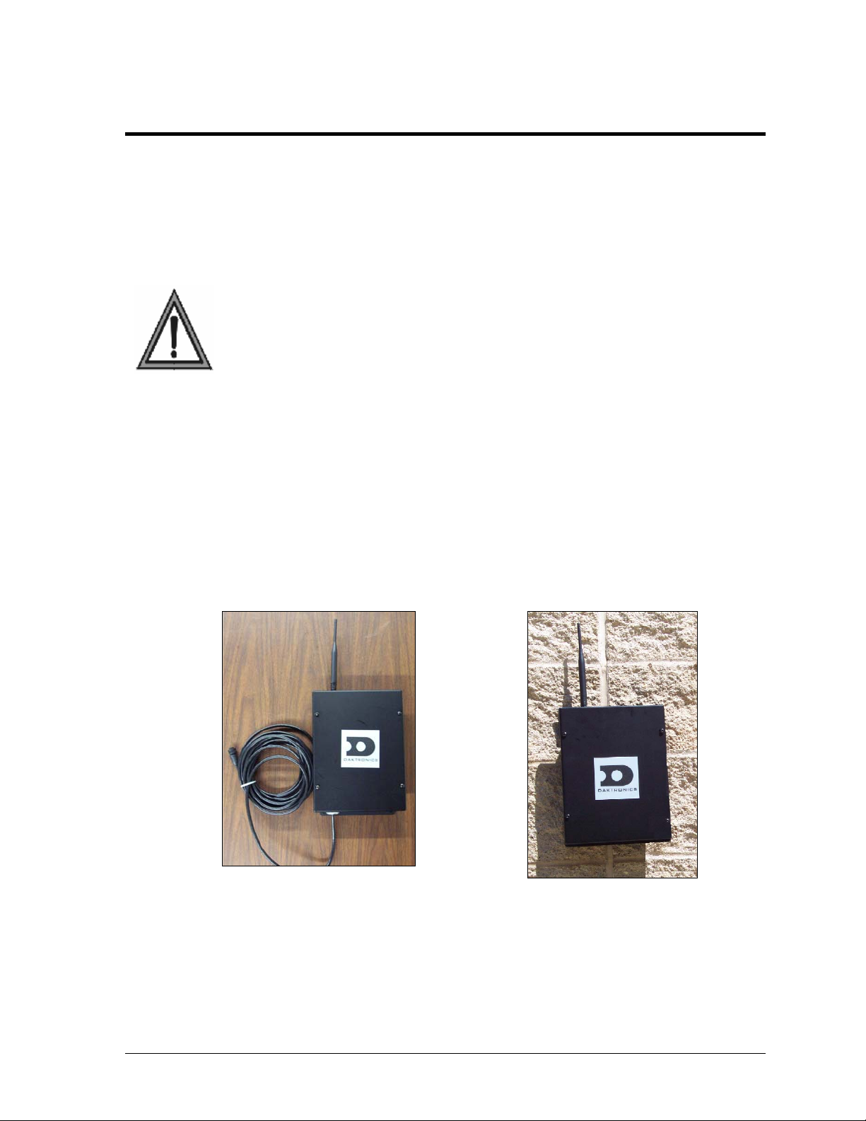
Client Radio: This radio must be mounted within 25 feet (8 m) of the display. It
communicates with the display via RS-232 signal. Power is provided by the display. A client
radio is shown in Figure 1.
Server Radio: This radio is connected to the control computer, sending information to the
display via the client radio. It is connected to the computer either directly or through a Jbox/signal converter. Server radios may be either outdoor or indoor types. An outdoor
server is shown in Figure 2.
Figure 1: Client Radio
Radio Channel: The channel set on the radios must be the same for all radios within the
same network. The default channel is 67, which corresponds to address 0 on the radio hex
dial.
Introduction 3
Figure 2: Server Radio
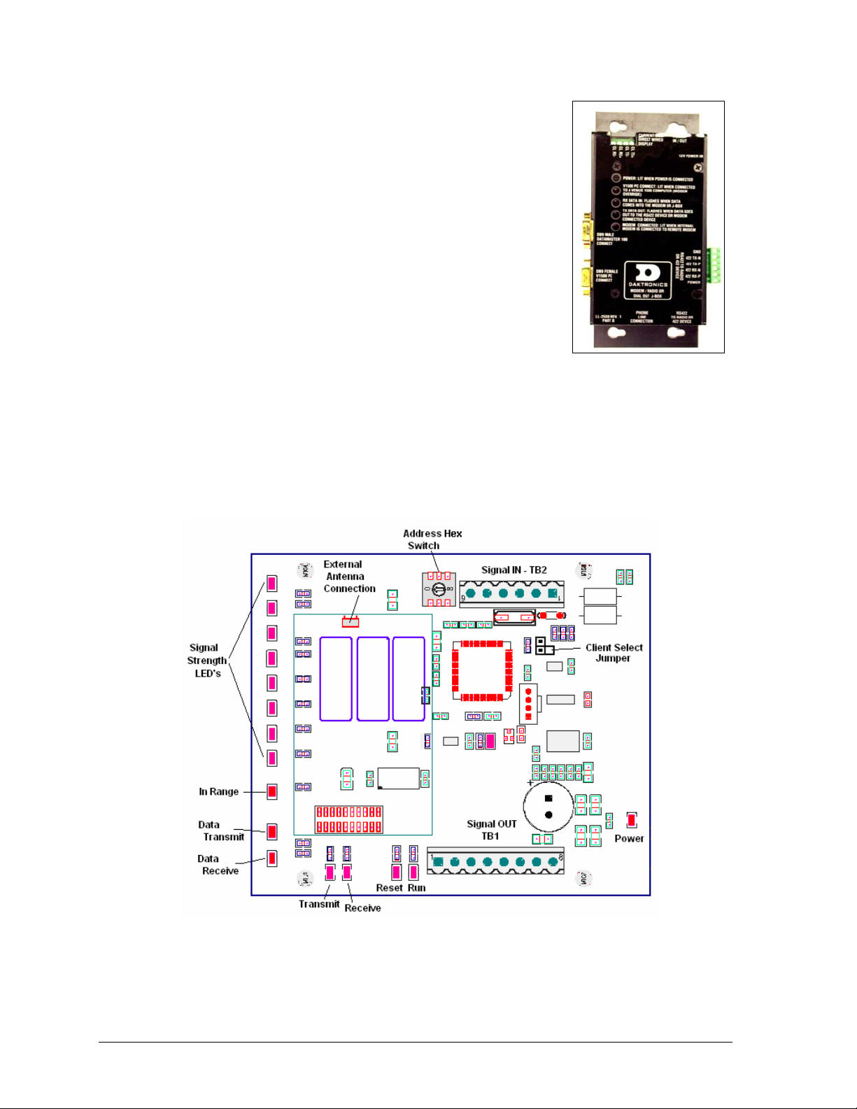
J-box/Signal Converter: In the case of Venus 1500-controlled
radios, a J-box/signal converter is used to send RS4-22 signal and
power to the server radio. The signal converter will be one of two
types: one that accepts serial information from a computer via
RS-232 and one that accepts RS-232 information and a modem or
dial-up input. The same J-box/signal converter (Figure 3) is used
with both the indoor and outdoor server radios.
RS-232: RS-232 is a standard PC communication type with a
maximum cable length of 25 feet (8 m). The output of the client
radio is RS-232.
RS-422: RS-422 is a standard differential communication type
with a maximum cable length between the J-box/signal converter
and the serial radio of 1000 feet (300 m).
Figure 3: J-box/Signal
Converter
Signal Strength Indicator: The server and client radios have
eight LEDs that are used to display signal strength. Refer to the left side of Figure 4.The
number of LEDs that are lit on the client radio indicates the signal strength, with eight being
full strength and one indicating a weak signal. The specific address needs to be set on the
server radio to display signal strength, as explained in Section 3.1.
Figure 4: Outdoor Server/Client Radio Board Layout
4 Introduction
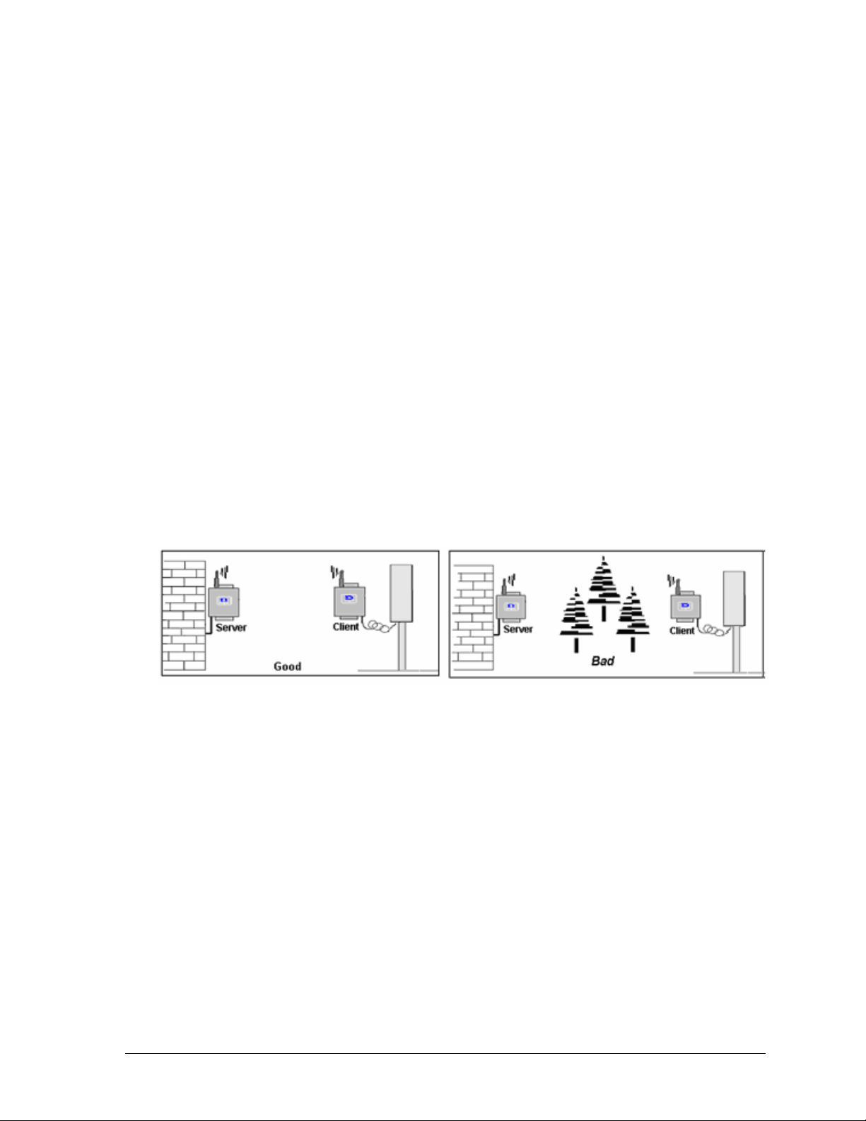
1.3 Site Selection
Due to the uncertainties associated with radio communication, it is recommended that the
radios be temporarily installed to check signal strength and consistency of communication.
Once the radios have proven reliable in a location, they can be mounted permanently.
The performance of high-frequency radios may be diminished by obstructions that impede
the signal. Therefore, a clear line-of-sight between antennas is required for optimum
performance at maximum range. Refer to Figure 5.
Obstructions that interfere with radio signal include but are not limited to:
• Electrical interference from power lines or street lights close to radio locations.
• Physical features, such as hills, large buildings, or trees.
• Telephone, radio, television towers, etc. in the immediate area.
• Two-way radios or other communication equipment used at the business.
• Transmission through glass, especially security glass, and communication through a
doorway in indoor installations.
If the radios are not working at optimal performance levels, communication may be slowed
or even lost. In addition, weather conditions, such as strong winds, rain, or snow may
adversely affect the communication signal. The type of message sent can also affect the time
needed to download to the display, with graphic frames and animations taking greater time
than simple text messages.
Figure 5: Good Site and Obstructed Site
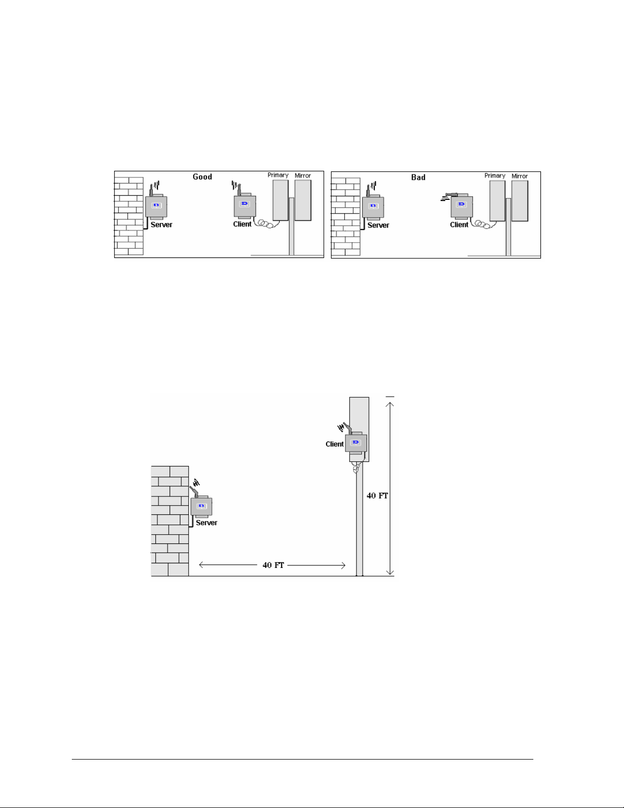
1.4 Line-Of-Sight
The radios operate at 2.4 GHz. Radio waves at high frequencies such as this travel in a nearly
straight line-of-sight path. To relay strong signal, the radio antennas that communicate with
each other must be free of any obstructions. Refer to Figure 5.
To achieve optimal performance, the radios must meet the following criteria:
• A clear line-of-sight path among all antennas that communicate directly with each
other. Some obstruction may be tolerated in short range, but it is difficult to predict
the performance if the signal is obstructed.
• A maximum distance of 500 feet (150 m) indoors and 1,500 feet (450 m) outdoors
between server and client radios. The signal strength indicator LEDs will show the
maximum range of the radios possible in a specific location.
• All antennas be properly oriented. The antennas distributed with the radio are dipole
antennas that must be oriented in a parallel position for maximum performance.
• The presence of other radio signals may also cause interference if they are located in
or near the line-of-sight.
Introduction 5
1.5 Antenna Orientation
The radios come with high quality dipole antennas. Dipole antennas perform the best when
information is being received on the broadside of the antenna. To maximize the performance,
mount the radios so that their antennas are in an upright position and are on equal
elevations.
Figure 6: Correct/Incorrect Antenna Orientation
An inclination of more than 45 degrees from a perfect parallel position may reduce the
performance of the radios by more than half. However, dipole antennas are not directional
and will transmit signal equally for 360 degrees around the antenna.
A difference in elevation may be allowed depending on the distance and orientation of the
antennas. If both antennas are angled at 45 degrees, performance can again be maximized.
Refer to Figure 7 for details.
Figure 7: Correct Antenna Orientation at Elevations
1.6 Channel Number
The channel number is a parameter that must be the same for all server and client radios in
the same network. Each product line will have a set of channels on which the radios may
operate. The Venus 1500 radio can operate on channels 67-74. The default channel is 67,
which corresponds to address 0 on the radio’s hex dial. To change the radio address, refer to
Section 3.1.
6 Introduction

1.7 Baud Rate
If a modem is used for signal transmission, the baud rate must also be the same for all the
server and client radios in the same network. This parameter will also be unique to each
product line. The Venus 1500 radio default configuration is 19200, and has been set prior to
shipment.
Introduction 7


Section 2: Installation Guidelines
2.1 Site Survey
For maximum performance of the Venus 1500 radio system, survey the installation site and
answer the following questions:
• Is a direct line-of-sight possible between the server and client radios?
• Will the distance between the outdoor radios be less than 1500 feet (450 m), and
between the indoor radios less than 500 feet (150 m)? If not, is it possible to achieve
the required distance?
• Where will the radios need to be located in order to achieve the required direct line-
of-sight?
• Is there an optional location for the radios in case of interference that may degrade
the quality of the radio signal?
• Should maintenance be required, will the radios be easy to access?
2.2 Server Radio Installation
Installation of a radio system consists of two parts:
• connecting a server radio to a computer either directly or over a phone line.
• connecting a client radio at the display. Refer to Section 2.4 for this information.
Two types of server radios may be installed, outdoor or indoor, depending on the location of
the display. The most common is the outdoor server radio mounted to the outside of a
building and communicating with the client radio located near an outdoor display. An
indoor server radio is also available that communicates with the client radio mounted near
an indoor display. This type of installation is most common with a message
center/scoreboard setup.
To work correctly, the server and client radios must be set to the same channel in order to
communicate with each other. Daktronics will set them to the same default channel before
they are shipped to the customer. If a different channel is required because of multiple radio
sets near each other, the channels on both radios will need to be set accordingly. Addressing
information is located in Section 3.1 of this manual.
2.3 Installing a Server Radio
Warning: Cat-5 cable is not recommended in this installation. The distance that power
and signal can travel may vary with the use of Cat-5 cable. If Cat-5 cable is pulled, use
one pair for the ground (pin 6) and one pair for the power (pin 1). Do not place Cat-5
cable in this application next to Ethernet communication cables or signal loss may occur.
This section includes instructions for installing a server radio with either of these two
options:
• directly to the computer through a J-box/signal converter or
• remotely through a modem.
Installation Guidelines 9
The J-box/signal converter and J-box/modem look very similar. The connection from the Jbox to the server radio is the same in both cases and only the input signal to the J-box will
vary.
Direct Server Installation
Reference Drawings:
System Riser Diagram; QC Outdoor Radio, Gen 2...............................
Warning: Cat-5 cable is not recommended in this installation. The distance that
power and signal can travel may vary with the use of Cat-5 cable. If Cat-5 cable is
pulled, use one pair for the ground (pin 6) and one pair for the power (pin 1). Do not
place Cat-5 cable in this application next to Ethernet communication cables or
signal loss may occur.
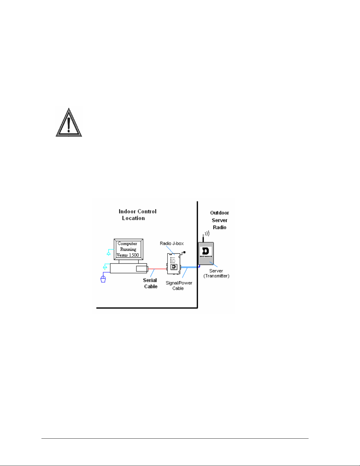
Install the J-box /signal converter near the control computer. Mount the server radio at an
outdoor location in a direct line-of-sight path with the client radio. Route the signal/power
cable between the J-box and the server radio. The maximum distance between the J-box to
the server radio is 1000 feet (300 m). Refer to the system riser Drawing A-211606, and Figure
8 for more information.
Drawing A-211606
10
Figure 8: Server Radio Installation
The following directions are provided for connecting from the computer to the server radio:
1. Plug the serial cable’s 9-pin male connector into the J-box at the jack labeled “DB9
Female V1500 PC Connect”. Plug the 9-pin female connector into the RS-232 COM
port on the computer.
2. Plug the J-box/signal converter’s power adaptor into a 120 VAC grounded outlet.
3. Plug the jack into the J-box at the port labeled 12V power IN.
4. Connect the power/signal cables as follows:
• Run the 6-conductor, 18 AWG stranded cable from the J-box to the server radio.
• Connect the wires at the phoenix plug (labeled RS-422 to Radio) on the J-
box/signal converter.
• Connect the wires to the phoenix plug labeled TB2 (RS422 IN) on the server
radio board. The cable is pinned one-to-one.
Installation Guidelines
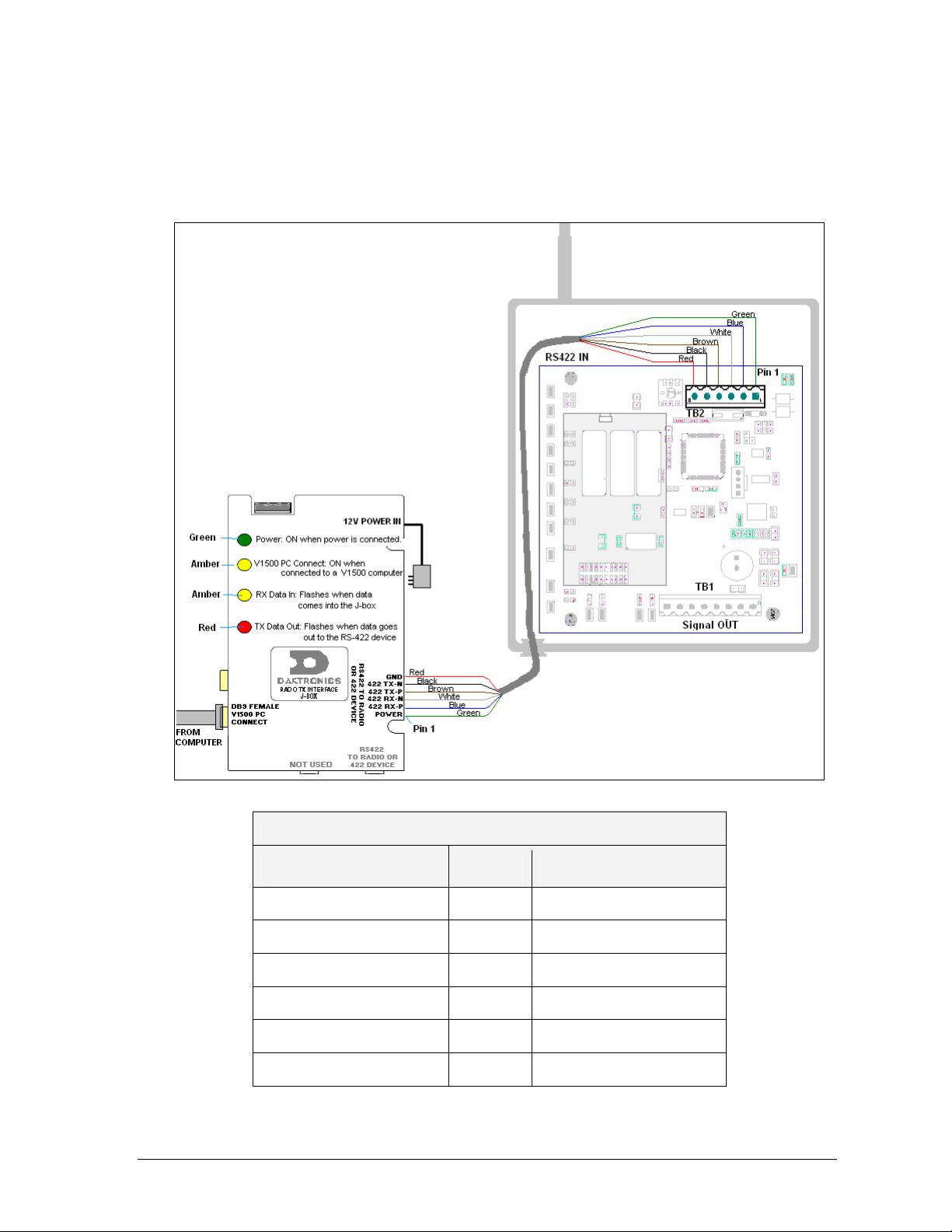
5. Refer to Figure 9 and the included table for connections from the J-box/signal
converter to the server radio.
Note: When exposed to outdoor conditions, the signal/power cable must be in conduit.
Figure 9: Direct Wiring, J-box to Outdoor Server Radio
J-box/signal converter
RS422 to Radio (TB1)
J-Box/Signal Converter to Server Radio
Cable
Color
Server Radio
Signal IN (TB2)
Pin 1 (POWER) Green Pin 1 (+V UNREG)
Pin 2 (422 RX-P) Blue Pin 2 (422 TX-P)
Pin 3 (422 RX-N) White Pin 3 (422 TX-N)
Pin 4 (422 TX-P) Brown Pin 4 (422 RX-P)
Pin 5 (422 TX-N) Black Pin 5 (422 RX-N)
Pin 6 (GND) Red Pin 6 (GND)
Installation Guidelines 11
Server Installation via Modem
Reference Drawings:
System Riser Diagram; Modem/QC Outdoor Radio, Gen 2 ................. Drawing A-242383
Warning: Cat-5 cable is not recommended in this installation. The distance that
power and signal can travel may vary with the use of Cat-5 cable. If Cat-5 cable is
pulled, use one pair for the ground (pin 6) and one pair for the power (pin 1). Do not
place Cat-5 cable in this application next to Ethernet communication cables or signal
loss may occur.
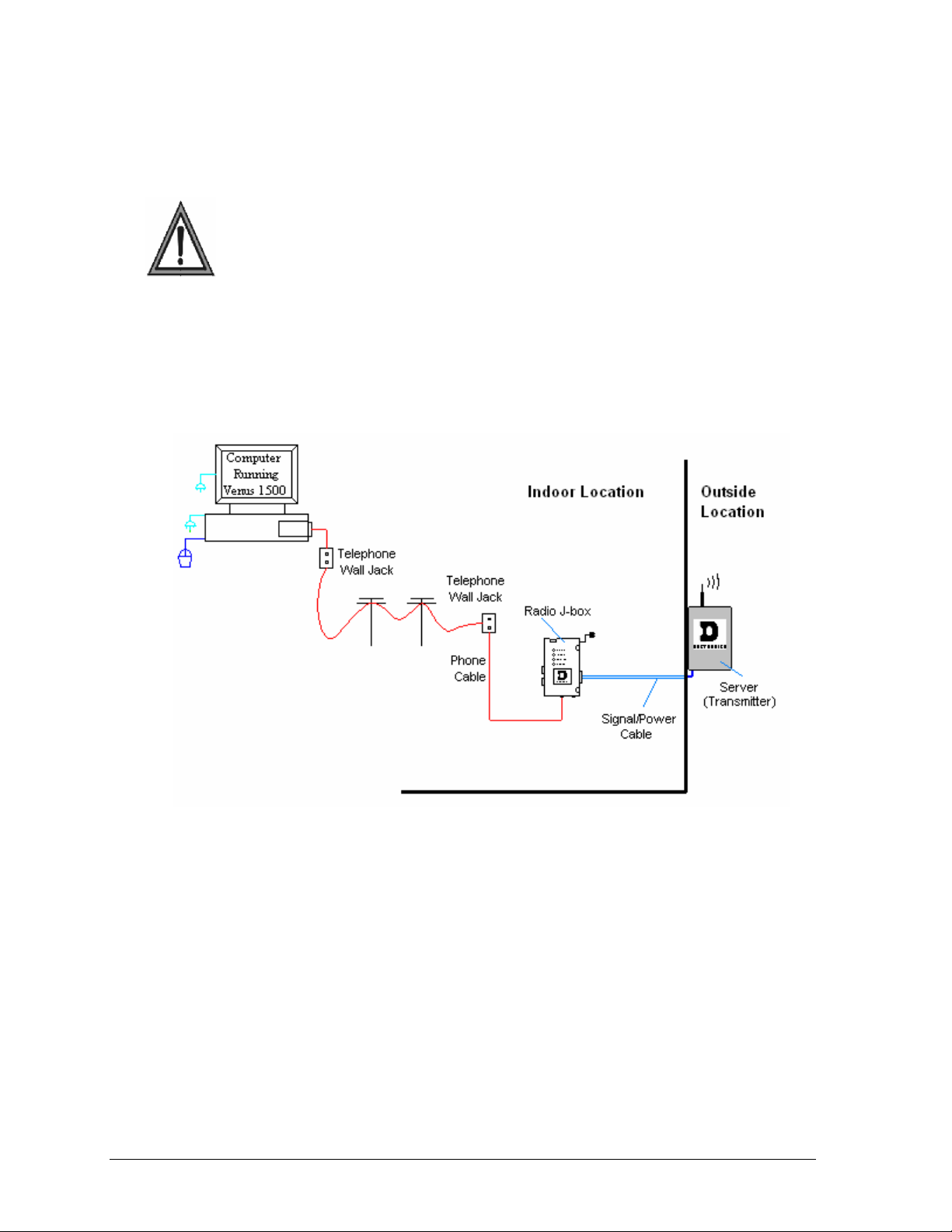
The modem signal system allows the control software to call another location using a dial-up
network. A signal is then sent to the server radio via a J-box/ modem at a second location.
This section will explain how to connect to the server radio from the J-box. The maximum
distance from the J-box to the server radio is 1000 feet (300 m). Refer to the system riser
Drawing A-242383, and Figure 10 for more information.
12
Figure 10: Remote Location to Server Radio via Modem
The following directions are provided for connecting from the computer to the server radio:
1. Using a flipped, 6-conductor, 26 AWG, stranded silver satin cable, plug one end of
the RJ-11 cable into the telephone wall jack. Plug the other end into the Jbox/modem, at the jack labeled “Phone Line Connection”.
2. Plug the J-box’s power adaptor into a 120VAC grounded outlet. Plug the jack into
the J-box/modem at the port labeled 12V power IN.
3. Connect power/signal cables as follows:
• Run the 6-conductor, 18 AWG stranded cable from the J-box/modem to the
server radio.
• Connect the wires at the phoenix plug (labeled RS-422 Out to Radio) on the J-
box/modem.
• Connect the wires to phoenix plug labeled TB2 (RS-422 IN) on the server radio
board. The cable is pinned one-to-one.
Installation Guidelines
Loading...