

Page 1

Failure diagnosis tool for ZEAS_A type
Digital Pressure Gauge Kit
BHGP26A1(E)(H)
RDUH11-063
Connected model
ZEAS (A type)
LRLEQ5AY1(E), LRLEQ6AY1(E), LRLEQ8AY1(E), LRLEQ10AY1(E),
LRLEQ12AY1(E), LRLEQ15AY1(E), LRLEQ20AY1(E)
LRMEQ5AY1(E), LRMEQ6AY1(E), LRMEQ8AY1(E), LRMEQ10AY1(E),
LRMEQ12AY1(E), LRMEQ15AY1(E), LRMEQ20AY1(E)
Page 2

Contents
1. Preparation before Connection of
Digital Pressure Gauge Kit............................................2
2. Overview of Product ......................................................2
3. Connection Drawing ......................................................4
4. Display Item and Method of Operation ........................7
4.1 Normal ............................................................................ 7
4.2 Abnormal......................................................................... 7
4.3 Manual Operation Display 1............................................ 8
4.4 Manual Operation Display 2.......................................... 13
5. Service Diagnosis ........................................................15
6. The Entire Flow ............................................................16
1
Page 3
1. Preparation before Connection of Digital Pressure Gauge Kit
When the Digital Pressure Gauge Kit is connected to the outdoor unit, please confirm the software version of
control PCB of ZEAS and you need to change the software if necessary.
∗ Please refer to the manual of software writing delivered.
Check the Software of Condensing Unit
z
Condensing unit: If ver. 91 or earlier, please update the software ver. 93 or later.
z
Condensing unit: ver. 93 and later...You do not need to change the software.
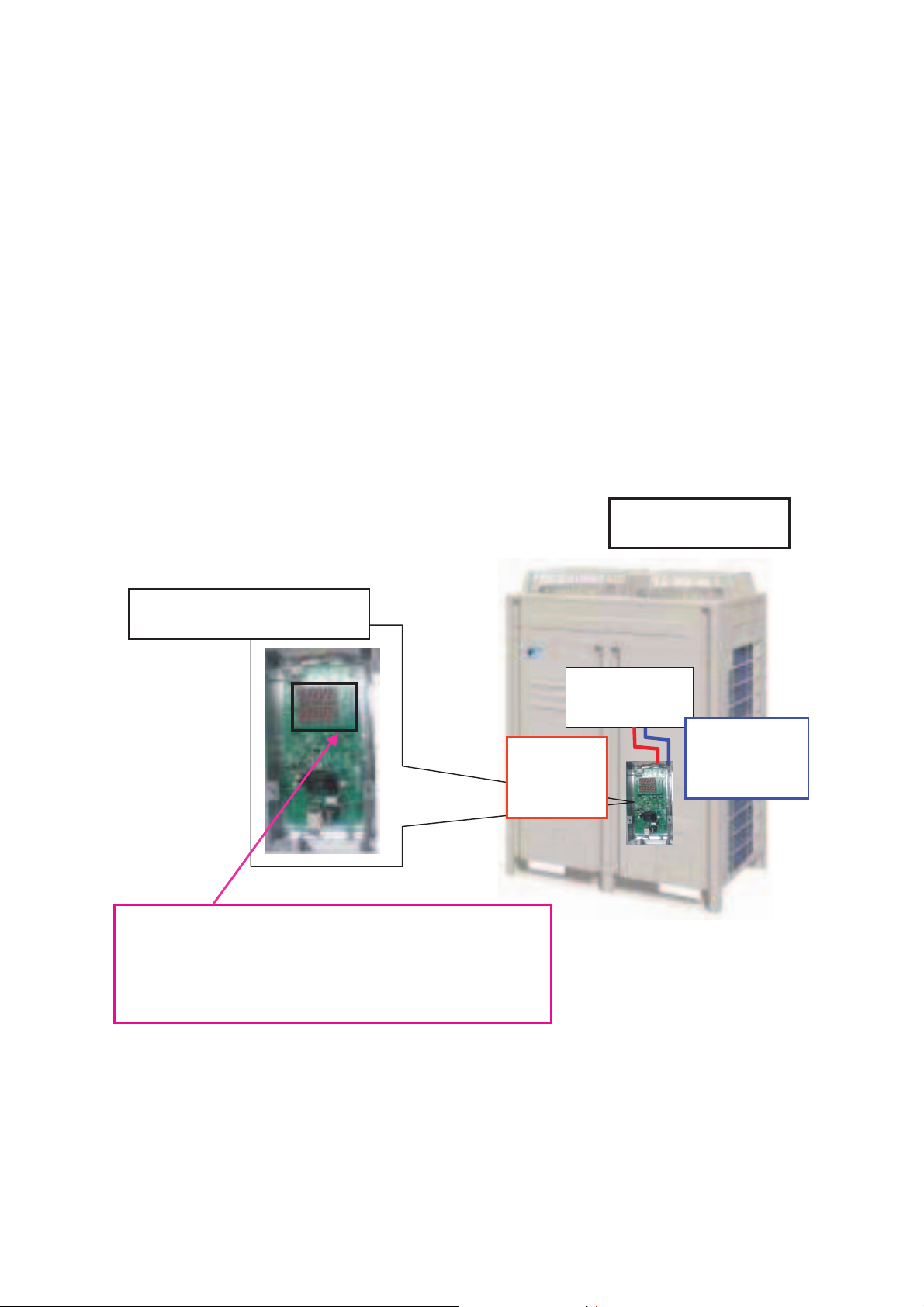
2. Overview of Product
Communicated image
Condensing Unit
Digital Pressure Gauge Kit
7 segment display
Pressure and temperature, detail of running data,
Error code of outdoor unit, software version.
Power
supply line
Control PCB
Communication
line
∗ Power supply line and communication line are included with BHGP26A1.
2
Page 4

Specification of Digital Pressure Gauge Kit
Outdoor Temp. range –20°C~65°C
Power supply AC200-240V (+10%, –15%) 50/60Hz
Dimensions Height (mm) 268
Width (mm) 286
Depth (mm) 47.5
Casing Pressure gauge box main
body
Hot-dip zinc-coated steel sheets
Pressure gauge (cover) Metacrylate resin
Mass 1.8kg
Location Inside casing of outdoor unit
3
Page 5
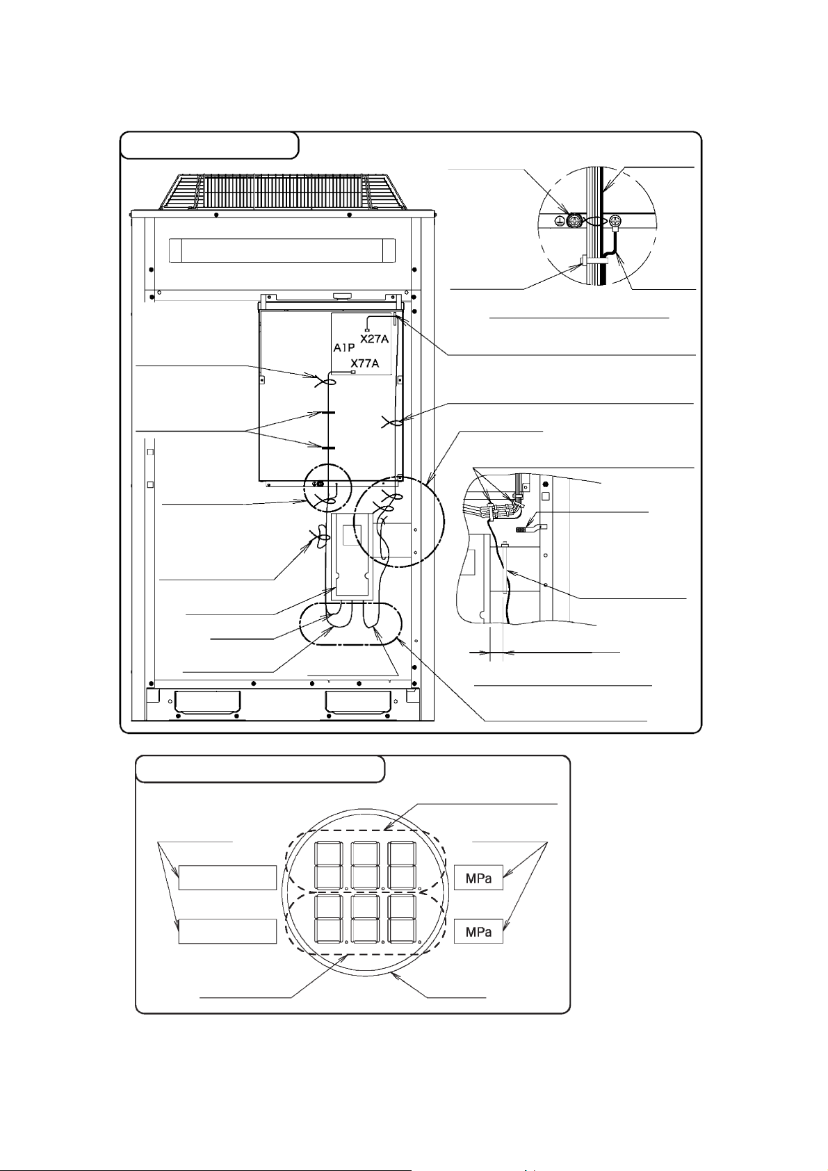
3. Connection Drawing
Wiring drawing
Bind the power supply line
with a clamp together with
the line connected to the
outdoor unit.
Insert the power supply line
into a wire clip together with
the line connected to the
outdoor unit.
Section B
Bundle the redundant length
portion so that the power
supply line or ground wire
will not come in contact with
the conduit.
Digital Pressure
Gauge Assembly
On-site ground
terminal
Bind the power
supply line and
ground wire with
a clamp together
with the line
connected to the
outdoor unit.
Power supply
line
Ground wire
Section B detail view
Insert the communication line into a wire clip
together with the line connected to the outdoor unit.
Bind the communication line with a clamp together
with the line connected to the outdoor unit.
Section A
Bind the communication line with a clamp together
with the line connected to the outdoor unit.
Thermistor
Bind the internal wires
with the large-sized
clamp so that the wires
will not come in contact
with the thermistor.
Ground wire
Power supply line
Communication
line
Label pasting drawing
Gauge window
label
DISCHARGE
SUCTION
Suction pressure
display
20 mm max.
Section A detail view
Be careful not to tense the wire.
Discharge pressure display
Gauge window
label
Resin bush
C: 2P190979
4
Page 6
Punch out the
knock hole on the
left-hand side.
Knock hole on the front panel
Connection drawing
1. Turn the outdoor unit power OFF.
2. Remove the front panel. (If the model has two front panels (i.e., one each on the left-hand side and righthand side), remove the panel on the right-hand side only.)
3. Remove the lid of the electrical box.
4. Refer to the and mount the Digital Pressure Gauge Assembly to the panel on the righthand side.
[Parts used: Digital Pressure Gauge Assembly: 1, M5×12 screw: 2]
5. Secure the ground wire to the electrical box with a screw.
Refer to section B (detail view) in the for the screwing position.
[Parts used: M4×12 screw: 1]
6. Connect the power supply line and communication line of the Digital Pressure Gauge
Assembly to the control PCB (A1P) in the electrical box.
• Power supply line: Connector (white) • X77A
• Communication line: Connector (blue) • X27A
At that time, wire the communication line behind the Digital Pressure Gauge Assembly.
(Refer to section A (detail view) in the .)
7. After connecting the power supply line, communication line, and ground wire, secure the wiring path
according to the .
[Parts used: Clamps: small 6, large 1]
8. Mount the lid of the electrical box.
9. Punch out the knock hole with a diameter of 70 mm on the front panel. (Refer to the mounting dimensions
on the upper right-hand side.)
10.Attach the resin bush to the knock hole on the front panel. [Parts used: Resin bush: 1]
11.Mount the front panel.
12.On completion of installation, turn the outdoor unit power ON and make sure that pressures are displayed
normally.
When figures appear in the discharge pressure display and suction pressure indicate, the product is
working normally.
(Pressure is indicated in the operation switch "OFF or ON" of outdoor unit.)
Abnormal upper section: Error code, Abnormal lower section: LP
Abnormal display case: Please refer to the service diagnosis P.15
Installation drawing
Wiring drawing
Wiring drawing
Wiring drawing
C: 2P190979
5
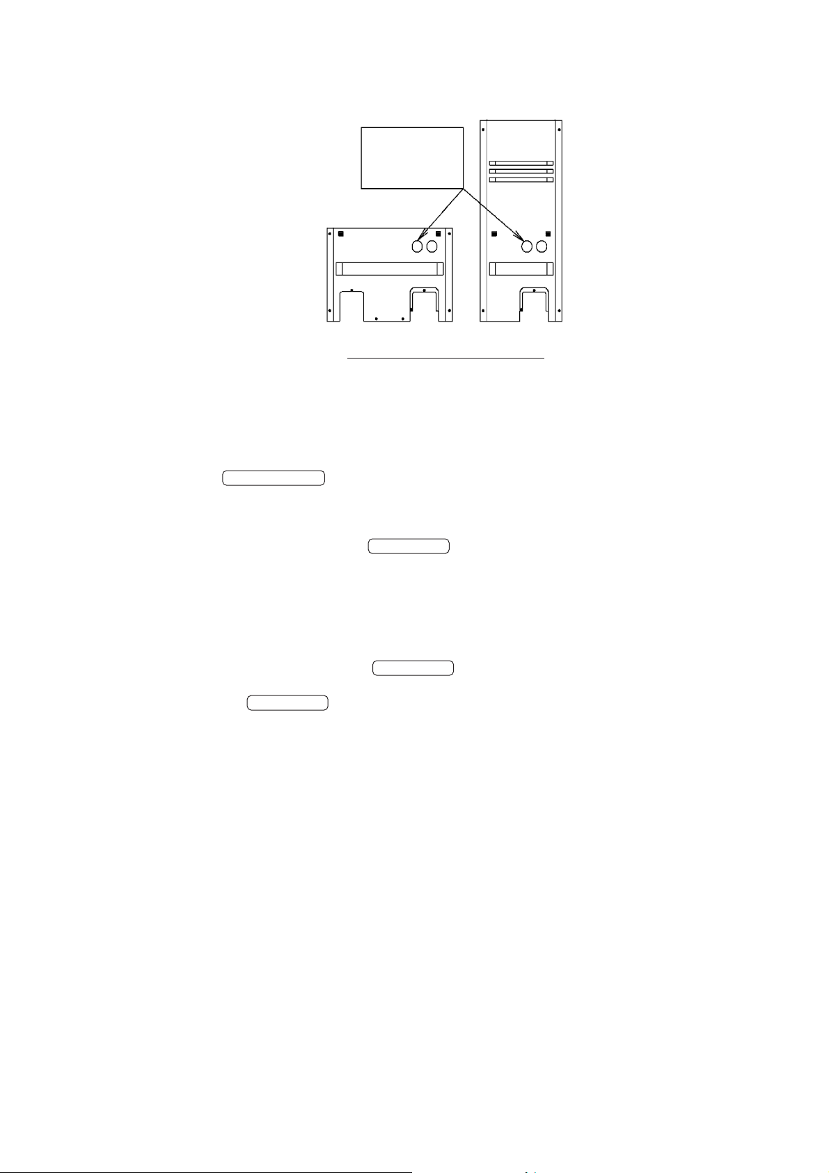
Page 7

Attention in the display.
Digital Pressure Gauge Kit and RAM-monitor can not be used at the same time for communication line is
connected to X27A of control PCB of outdoor unit.
Installation drawing
Communications line: Connector (blue)
Ground wire
Power supply line: Connector (white)
Right-hand-side
panel
M5×12 screws
Digital Pressure Gauge Assembly
2P190979
6
Page 8

4. Display Item and Method of Operation
Display item
There are four major display items as follows:
4.1: Normal; Displays high pressure and low pressure in MPa
4.2: Abnormal; Error code is blinking, which should be seven-segment blinking display for attention
seeking.
4.3: Manual Operation Display 1; Check the individual operation data. (compressor operation
frequency, target evaporation temperature, etc.)
4.4: Manual Operation Display 2; Check error history for the preceding 3 times.
4.1 Normal
High pressure is displayed in the upper section, and low pressure is displayed in the lower section with
lighting display for both.
Display examples are shown below:
4.2 Abnormal
If error occurs, error code blinks in the upper section automatically. The low pressure is kept displayed in the
lower section.
Both upper and lower section are blinking.
After reset the error, "4.1 Normal" is automatically displayed again.
Note:
If the low pressure sensor is abnormal (error code:
zDisplay example
Upper section
High pressure (HP)
Lower section
Low pressure (LP)
Lighting LED : Upper section and lower section
Unit: MPa
Unit: MPa
JC
), correct low pressure is not displayed.
zDisplay example
Upper section
Error code E9
Lower section
Low pressure (LP)
Blinking LED : Upper section and lower section
7
Page 9

4.3 Manual Operation Display 1
On the Manual Operation Display 1, you can check the individual operation data. (compressor operation
frequency, target evaporation temperature, etc.)
z
Table 1 on P. 9 shows how to set Manual Operation Display 1.
z
Table 2 on P. 10,11 shows which operation data you can check.
∗ Cautions for Manual Operation Display 1
1. Each display item is displayed by automatic scroll (interval of 3 sec.) in the order of display No.
2. After display No. 32 displayed, automatically returns to display No. 1
3. After 120 minutes of continuous displaying, the display is automatically returned to the initial display so
that it will not be lost.
4. Display items and values are fixed by pressing the RETURN (BS3).
Display is returned to automatic scroll by pressing the RETURN (BS3) again.
Note 1: Once display item is fixed, the fixed value is maintained.
Note 2: Display is fixed for up to 2 minutes. After 2 minutes, returns automatically to scroll display
5. Display digit number
Pressure and temperature data are displayed in the top 3 digits. The 4th digit is cut out.
If the displayed value is below 0, it is displayed in the top 2 digits with negative sign "-". The third digit is
cut out.
Display examples are shown below:
zDisplay example
(1) When the suction pipe temperature of INV.
compressor is 20.89 ˚C, 20.8 ˚C is displayed.
(2) When the suction pipe temperature of INV.
compressor is -20.9 ˚C, -20 ˚C is displayed.
Upper section
ti
Lower section
20.8
Upper section
ti
Lower section
-20
6. Display in case horsepower is different
As for the outdoor unit with 5 to 12 HP, discharge pipe temperature, operation data of STD compressor,
and so on, are not displayed, as those data are produced from the equipment which is not equipped to the
outdoor unit.
In such case, "-" is displayed in the lower section.
zDisplay example
Display when LRLEQ5AY1 is connected
Upper section “td2”
Lower section “– – – ”
8
Page 10

Table1. Operation method of manual operation display 1
No.
Operation
LED display of outdoor unit
H1P H2P H3P H4P H5P H6P H7P
h
: OFF / k: ON / l: Blinking
Display example Remarks
Initial display
(Normally of connected
outdoor unit and Digital
Pressure Gauge Kit)
1
Initial display
(Abnormally of
connected outdoor unit)
2
Selection
Press the
TEST (BS4)
of manual
operation
display
3
Decision
of manual
4
operation
display
Display of
5
operation
data
Press the SET
(BS2)
Press the
RETURN
(BS3)
Press the
RETURN
(BS3)
Press the
RETURN
(BS3)
Fixed
display of
6
7 segment
Press the
RETURN
(BS3)
hhkhhhh
hkkhhhh
lhhlhhh
lhlhhhh
lhkhhhl
lhkhhhk
lhkhhhk
lhkhhhk
Upper section HP
Lower section LP
Upper section
Lower section LP
Upper section tE0
Lower section
value of tE0
Upper section tE0
Lower section
value of tE0
Upper section tE0
Lower section
value of tE0
Error code
∗1
∗1
∗1
∗1
∗1
∗1
Automatic scroll
indication (Interval of 3
sec.)
Display item refer to the
next page
Press the RETURN
(BS3): Fixed display of
7 segment
Fix display items and
value when pressed.
Example is shown left.
One more press the
RETURN (BS3):
Cancel of fixed display
of 7 segment
After cancel of fixed
display of 7 segment:
Return automatic scroll
(Interval of 3 sec.)
∗1 For a display example, “tE0” is displayed. Refer to the detailed information of display items on the
following page onward.
9
Page 11

Table2. Display items of manual operation display 1
After 3 sec.
Display
No.
1
2
3
4
5
6
7
8
9
10
11
12
13
14
15
Display item
Target evaporation temperature
LP
HP
INV. compressor frequency
Point of contact output/CCU
INV. compressor (M1C)/K1M
STD1 compressor (M2C)/K2M
STD2 compressor (M3C)/K3M
Operating output/K10R
Solenoid valve (Y2S)/K4R
Solenoid valve (Y5S)/K11R
Four way valve (Y3S)/K5R
Discharge pipe temperature
(INV. compressor)
Discharge pipe temperature
(STD1 compressor)
Discharge pipe temperature
(STD2 compressor)
Suction pipe temperature
Subcooling heat exchanger
inlet temperature
Subcooling heat exchanger
outlet temperature
Outdoor air temperature
Condensation pressure equivalent
saturation temperature
Evaporation pressure equivalent
saturation temperature
Outdoor unit heat exchanger
temperature (R6T)
LED display (7 segment)
Unit
Upper section
tE0
˚C
LP
MPa
HP
MPa
inV
rps
Point of contact
output “ON”: Lighting LED
–
–
–
–
–
–
–
td1
˚C
∗2
∗2
∗2
td2
˚C
td3
˚C
ti
˚C
∗2
∗2
tL
˚C
tg
˚C
∗2
tA
˚C
∗2
tC
˚C
∗2
tE
˚C
∗2
tCE
˚C
∗2
Connection unit (
Lower section
LRLEQ5 · 6AY1(E)
LRMEQ5 · 6AY1(E)
Value of display item
Value of display item
Value of display item
Value of display item
Value of display item
Value of display item
Value of display item
Value of display item
Value of display item
Value of display item
Value of display item
Value of display item
Value of display item
Value of display item
{: display target ∗: different HP)
LRLEQ8 · 10 · 12AY1(E)
LRMEQ8 · 10 · 12AY1(E)
LRLEQ15 · 20AY1(E)
LRMEQ15 · 20AY1(E)
{{ {
{{ {
{{ {
{{ {
{{ {
∗1
∗1
{{
∗1
{
{{ {
∗1
∗1
{{
∗1
{
{{ {
{{ {
∗1
∗1 ∗1
{{
{
{{ {
{{ {
{{ {
{{ {
{{ {
{{ {
{{ {
10
Automatic return from display item No.32 to item No.1.
∗1 No display is available as target equipments are not present.
∗2 In case each sensor is abnormal, correct value can not be displayed. Before checking the sensor
measurement, please check if there is an abnormal report.
Page 12

Display
No.
16
17
18
19
20
21
22
23
24
25
26
27
28
29
30
31
32
Display item
Suction air superheated
Discharge pipe superheated
(INV. compressor)
Discharge pipe superheated
(STD1 compressor)
Discharge pipe superheated
(STD2 compressor)
Secondary current valve of
INV. compressor
Current value of STD1
compressor
Current value of STD2
compressor
Current value of outdoor
unit FAN1
Current value of outdoor
unit FAN2
Radiation fin temperature
Total operation
compressor frequency
Outdoor unit fan tap
Opening degree of electronic
expansion valve 1
Opening degree of electronic
expansion valve 2
Opening degree of
electronic expansion valve 3
Operation state
Software version of PCB
Unit
K
∗2
K
∗2
K
∗2
K
∗2
A
∗2
A
∗2
A
∗2
A
∗2
A
∗2
˚C
∗2
Hz
–
pls
pls
pls
–
–
LED display (7 segment)
Upper section
SH
Lower section
Value of display item
tS1
Value of display itemValue of display item
tS2
Value of display item
tS3
Value of display item
AdC
Value of display item
An1
Value of display item
An2
Value of display item
AF1
Value of display item
AF2
Value of display item
tF
Value of display item
HzA
Value of display item
FtP
Value of display item
EV1
Value of display item
EV2
Value of display item
EV3
Value of display item
StA
Value of display item
Ver
Value of display item
Connection unit (
LRLEQ5 · 6AY1(E)
LRMEQ5 · 6AY1(E)
{: display target ∗: different HP)
LRLEQ8 · 10 · 12AY1(E)
LRMEQ8 · 10 · 12AY1(E)
LRLEQ15 · 20AY1(E)
LRMEQ15 · 20AY1(E)
{{ {
{{ {
∗1
∗1 ∗1
{{
{
{{ {
∗1
∗1 ∗1
{{
{
{{ {
∗1
∗1
{
{{ {
{{ {
{{ {
{{ {
{{ {
∗1
{{
{{ {
{{ {
∗1 No display is available as target equipments are not present.
∗2 In case each sensor is abnormal, correct value can not be displayed. Before checking the sensor
measurement, please check if there is an abnormal report.
11
Page 13

Note
{
Display No. 1: Target Evaporation Temperature
Displays target evaporation temperature which is set by using the target evaporation
temperature set with DIP switch of the outdoor unit and correction value of target
evaporation temperature by pressing BS button.
{
Display No. 13: Condensation pressure equivalent saturated temperature f (HP)
The value of saturated temperature calculated from the high pressure of display No. 3
{
Display No. 14: Evaporation pressure equivalent saturated temperature f (LP)
The value of saturated temperature calculated from the low pressure of display No. 2
{
Display No. 16: Suction air SH
The difference between the suction pipe temperature Ti of display No. 9 and the saturated
temperature at the low pressure of display No. 2.
{
Display No. 17: INV. compressor discharge pipe SH
The difference between the INV. compressor discharge pipe temperature Td1 of display
No. 6 and the saturated temperature at the high pressure of display No. 3.
{
Display No. 18: STD1 compressor discharge pipe SH
The difference between the STD1 compressor discharge pipe temperature Td2 of display
No. 7 and the saturated temperature at the high pressure of display No. 3.
{
Display No. 19: STD2 compressor discharge pipe SH
The difference between the STD2 compressor discharge pipe temperature Td3 of display
No. 8 and the saturated temperature at the high pressure of display No. 3.
{
Display No. 26: Value of operating compressor total frequency
The total frequency is calculated by the equation below.
Total frequency = frequency of INV. compressor + (frequency of STD compressor
number of STD compressor)
*1 The frequency of STD compressor is fixed to 166 Hz.
∗1
×
12
Page 14

4.4 Manual Operation Display 2
On the manual operation display 2, you can check error history for the preceding 3 times.
In this case, both upper and lower sections show lighting display.
The upper section indicates how many times error occurred in the history.
The lower section displays error code.
z
Table 3 on P. 14 shows how to set manual operation display 2.
Display example
z
Showing how many times error occurred in the history.
Upper section
1n1
Lower section
E4
The latest history of error
Display error code
After 3 sec.
After 3 sec.
Upper section
2n1
Lower section
F4
The last but one history of error
After 3 sec.
Upper section
3n1
Lower section
E3
The last but two histories of error
In case no error is present
z
Lighting LED : Upper section and Lower section
Upper section
“000”
Lower section
“000”
∗ Cautions for manual operation display 2
1. Each display item is displayed by automatic scroll (interval of 3 sec.) in the order of display No.
2. After display No. 3 displayed, automatically returns to display No. 1
3. After 120 minutes of automatic scroll, the display is automatically returned to the initial display so that it will
not be lost.
4. If booster unit is abnormal, a batch of error codes from outdoor units such as
EJ, EF
, etc. are displayed.
13
Page 15

Table3. Operation procedure of manual operation display 2
No.
Operation
LED display of outdoor unit
H1P H2P H3P H4P H5P H6P H7P
h
: OFF / k: ON / l: Blinking
Display example Remarks
Initial display
(Normally of connected
outdoor unit and Digital
Pressure Gauge Kit)
1
Initial display
(Abnormally of
connected outdoor unit
or Digital Pressure
Gauge Kit)
2
Press the
TEST (BS4)
Selection
of manual
operation
display
3
Press the SET
(BS2)
Press the
4 Display
RETURN
(BS3)
hhkhhhh
hkkhhhh
lhhlhhh
lhllhhh
lhkkhhh
Upper section HP
Lower section LP
Upper section
Lower section LP
Upper section
1n1
Lower section
The last error history
(Error code)
Error code
History of error :
automatic scroll
indicate (Interval of 3
sec.)
14
Page 16

5. Service Diagnosis
On completion of installation (P.4 3. Connection Drawing), turn the outdoor unit power ON and make sure that
pressures are displayed normally.
Abnormal display: Refer to “Service Diagnosis” below and take necessary remedies if no figures are
displayed. If the trouble do not fall under any of the items described, change the Digital Pressure Gauge Kit.
Error display and measurements
Error display Cause Remedy
The LED indicator is not lit
Power supply is not provided
to the outdoor unit.
Provide power supply to the outdoor unit.
1
All LEDs blink
2
blinks
The connector of the power
supply line is unplugged.
The power supply line is
disconnected or damaged.
Others
The connector of the
communications line is
unplugged.
The communications line is
disconnected or damaged.
The outdoor unit is not
compatible with the Digital
Pressure Gauge Kit.
Others
There is a high-voltage line
generating noise around the
communications line.
Insert the connector of the power supply
line.
Replace the power supply line.
Please change the Digital Pressure
Gauge Kit.
Plug in the connector of the
communications line.
Replace the communications line.
Check with a this service manual if the
outdoor unit is compatible with the Digital
Pressure Gauge Kit.
If the outdoor unit is not compatible, this
Digital Pressure Gauge Kit cannot be
used.
Please change the Digital Pressure
Gauge Kit.
Noise may be imposed on the
communications line. Separate the highvoltage line.
3
The outdoor unit has a defect.
Others
Refer to the Service Guide and remedy
the problem.
Please change the Digital Pressure
Gauge Kit.
15
Page 17

6. The Entire Flow
Outdoor unit data
Indicate start of 7 segment
Press the
RETURN
(BS3) once
Decide of error
operation display
operation display
Decide of manual
Press the
RETURN
(BS3) once
Select of manual
operation display
Manual operation display 1
Manual operation display 2
Press the
SET(BS2) once
Press the
Automatic scroll
indicate (new error
Indicate start of 7 segment
Press the RETURN
(BS3) once
SET(BS2) twice
of before 2 times)
history ~ error history
display mode
Manual operation
Indicate of manual
operation display 1
Indicate of manual
operation display 2
Error State
Error state of
before 1 time
Non-error State
Indicate start of 7 segment
operation display
Decide of manual
Indicate start of 7 segment
lhlhhhh lhkhhhl lhkhhhk
Select of manual
operation display 1
Select of manual
operation display 2
lhllhhh lhkkhhh
The entire flow
16
Press the TEST(BS4) once
communication line of Digital Pressure Gauge Kit.
· Press the MODE(BS1) once.
Initial display
(HP/LP or error code/LP)
· Abnormal state of power supply line or
OR
120 minutes have passed since display of manual operation display
of Digital Pressure Gauge Kit.
· Press the MODE(BS1) once.
· Error state of power supply line or communication line
·
OR
7 segment flow (Manual operation display 1)
HP/LP or error code/LP
7 segment flow (Manual operation display 2)
HP/LP or error code/LP
LED of outdoor unit flow
Manual operation display mode
hhkhhhh lhhlhhh
Initial display
hkkhhhh
h: OFF
k: ON
Error state (Lighting H2P of LED)
l: Blinking
 Loading...