


FR-4501K

Service Manual
S/M No. :
MAY. 2001
D AEW OO ELECTR ONICS CO., LTD.
http : //svc.dwe .co.kr
FR4501KN02
FR-4502K / FR-4502N
FR-4503N / FR-4504K
FR-4505K
MODEL :
FR-4501K / FR-4501N
✔
Caution
: In this Manual, some parts can be changed for improving, their
performance without notice in the parts list. So, if you need the
latest parts information,please refer to PPL(Parts Price List) in
Service Information Center (http://svc.dwe.co.kr).

1
TABLE OF CONTENTS
EXTERNAL VIEWS ................................................................................................................ 2
1. EXTERNAL SIZE & NAME OF PARTS...................................................................................... 2
SPECIFICATIONS .................................................................................................................. 9
1. OUTLINE ..................................................................................................................................9
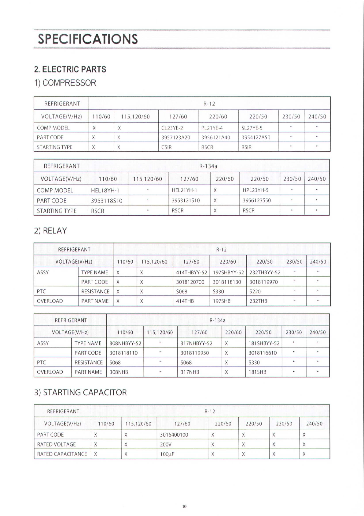
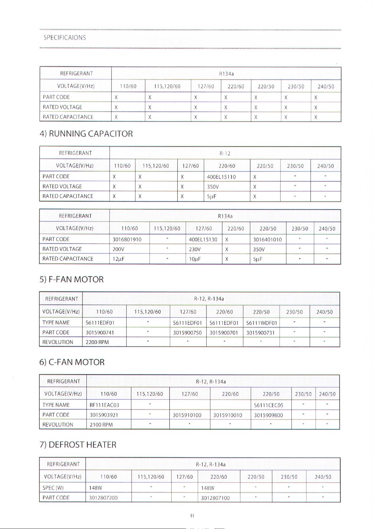
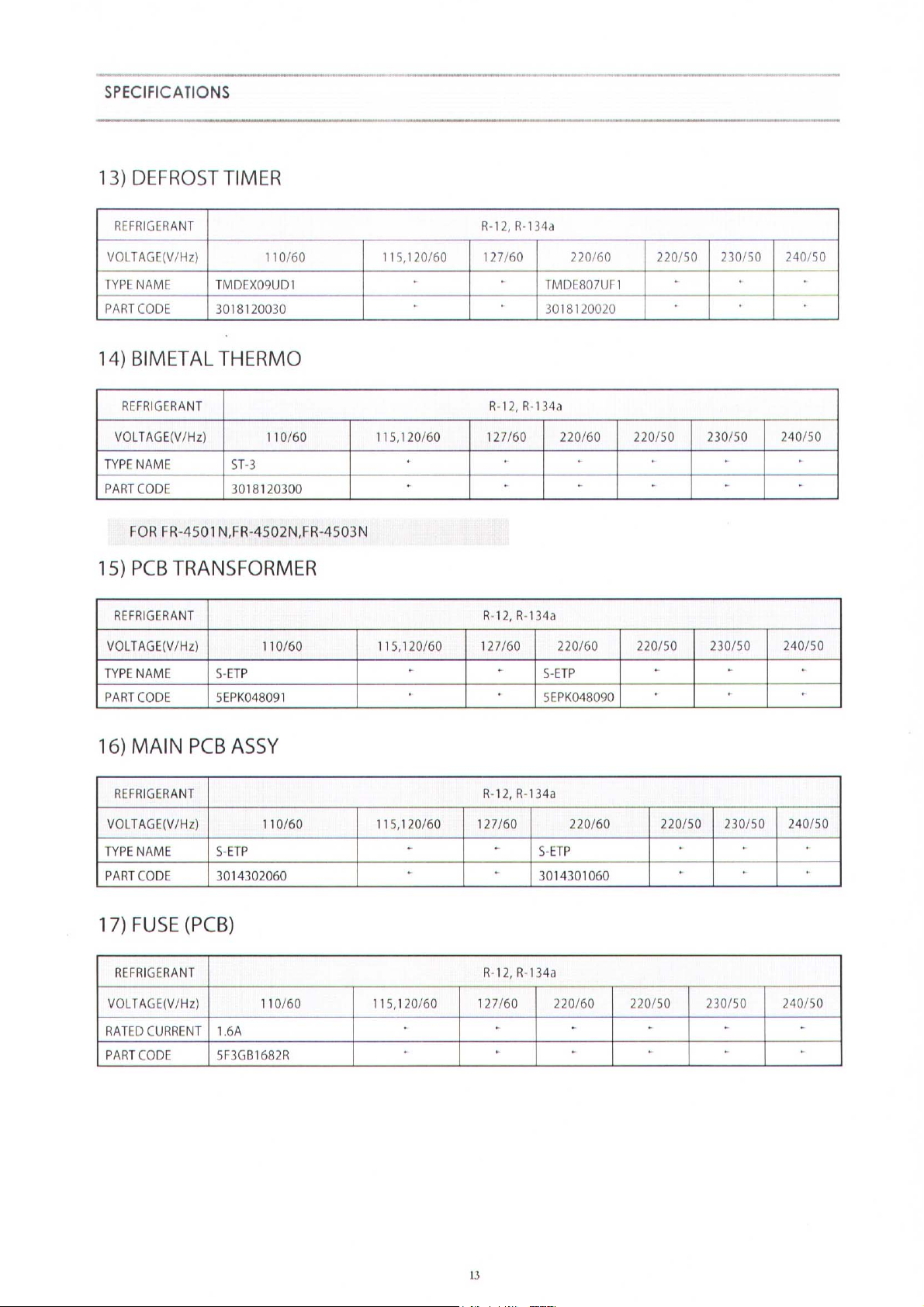
2. ELECTRIC PARTS ....................................................................................................................10
3. POWER CORD...........................................................................................................................15
OPERATION AND FUNCTIONS..............................................................................................16
DIAGRAM.................................................................................................................................22
1. WIRING DIAGRAM.....................................................................................................................22
2. CIRCUIT WIRING DIAGRAM.....................................................................................................23
3. AIR FLOW DIAGRAM.................................................................................................................24
4. REFRIGERATOR CYCLE DIAGRAM........................................................................................25
DISASSEMBLY AND ASSEMBLY...........................................................................................26
EXPLODED VIEW AND PARTS LIST......................................................................................32
1. TOTAL EXPLODED VIEW.........................................................................................................32
2. TOTAL PARTS LIST...................................................................................................................39
3. MACHINE ROOM EXPLODED VIEW AND PARTS LIST..........................................................66
SAFETY AND PRECAUTIONS
1) For starters, be sure to check any chances of the leakage of electricity."
2) You could handle a part in the vicinity of electricity after unplugging.
3) You should put on rubber gloves to prevent an electric shock on operation test.
4) Make sure the rated current,voltage,capacity before using an instrument."
5) Keep your wet hands away from the metal goods in the freezer compartment
not to be frostbitten.
6) Be careful not to let water permeate the electric part in the machine room.
7) With door open during your working,you might be damaged by door."
8) You should give a title to the refrigerator for your safe after removing the breakable
goods inside the refrigerator.
9) You'd better use cotton gloves if you fix it up around the evaporator
PRECAUTIONS TO BE OBSERVED BEFORE AND
DURING SERVICING TO AVOID POSSIBLE
EXPOSURE TO EXCESSIVE MICROWAVE ENERGY
2
EXTERNAL VIEW
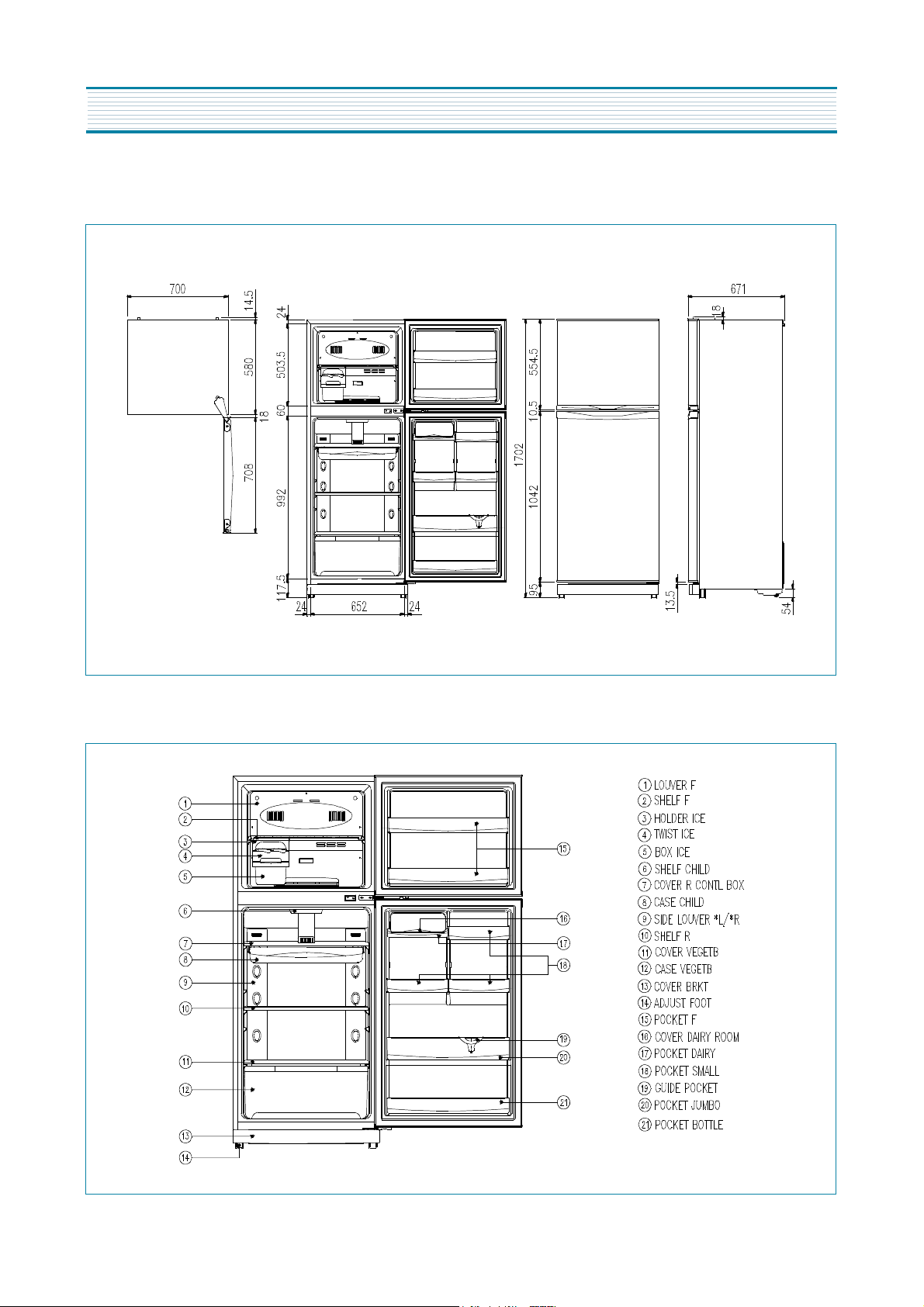
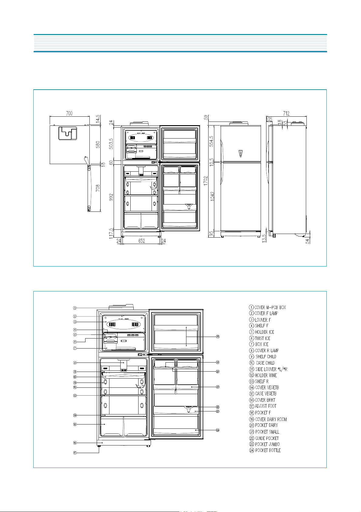
1. FR-4501K
1) EXTERNAL SIZE
2) NAME OF PARTS
?
3
EXTERNAM VICE
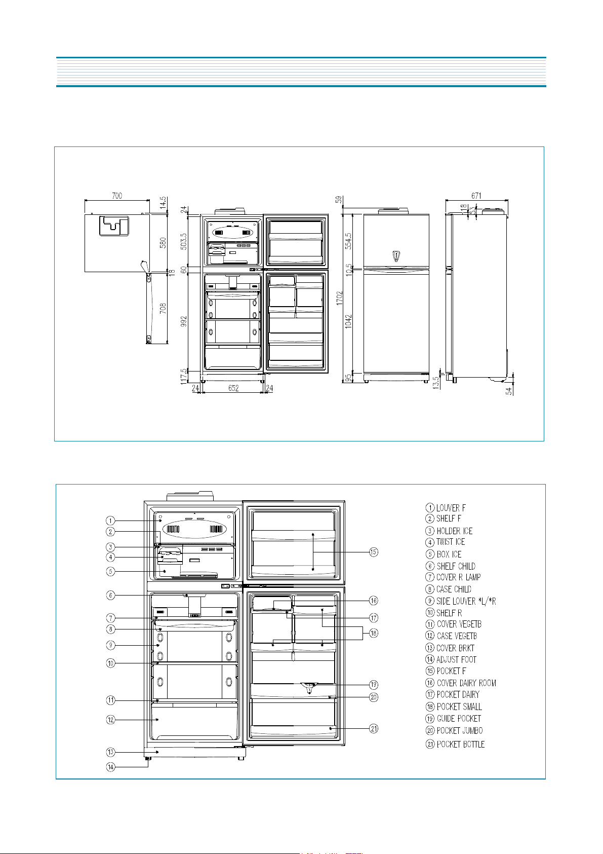
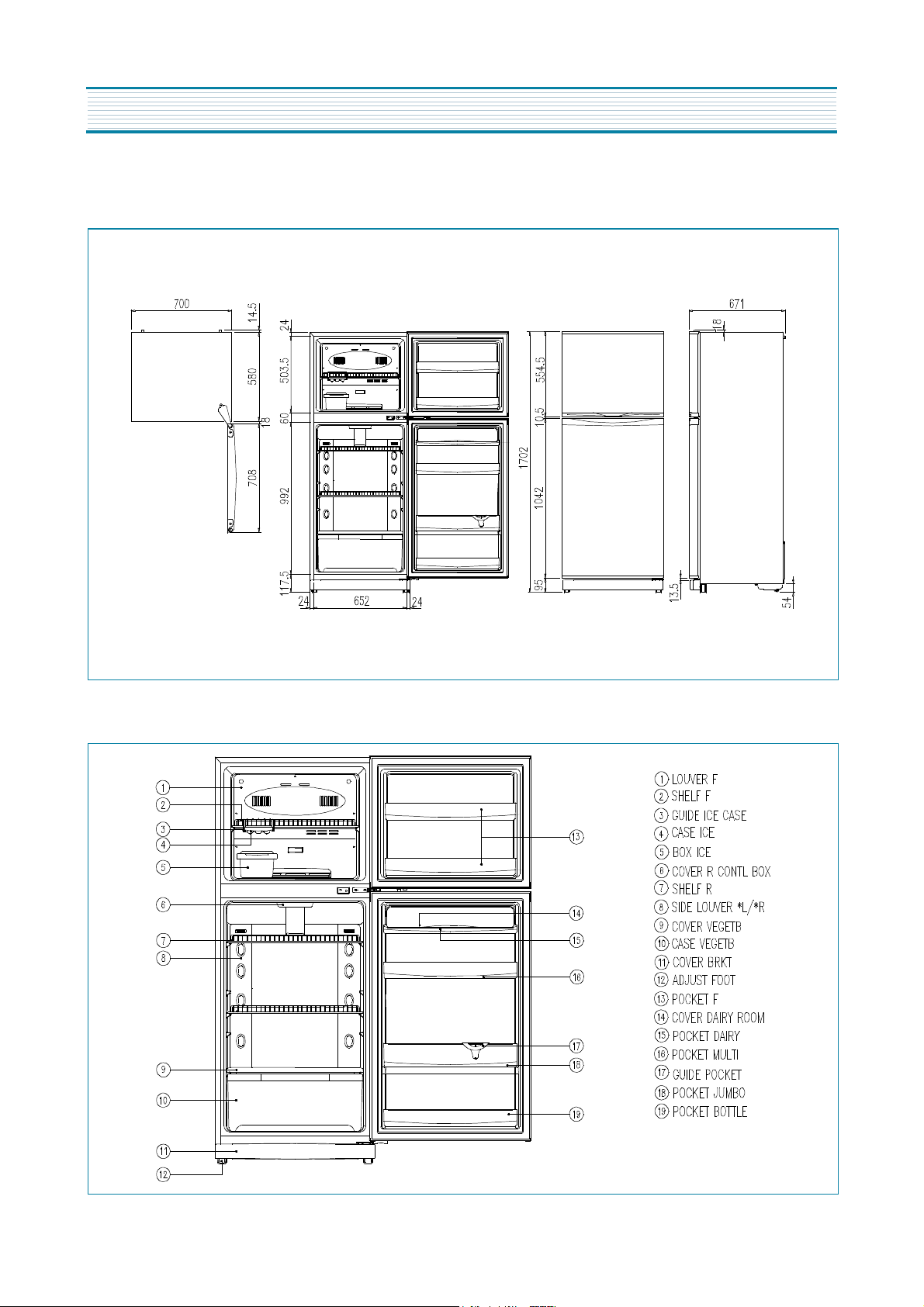
2. FR-4501N
1) EXTERNL SIZE
2) NAME OF PARTS
?
4
EXTERNAM VICE
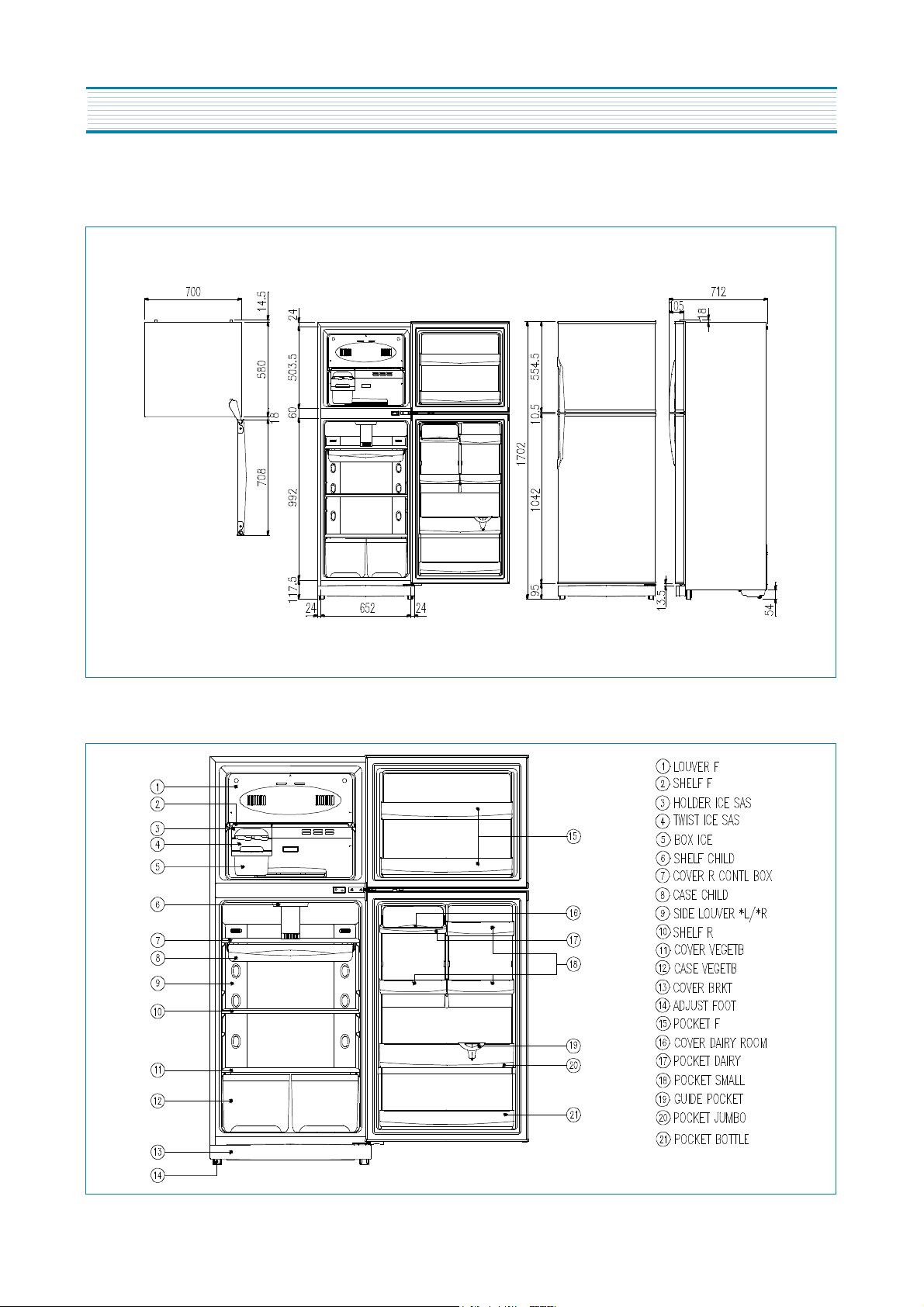
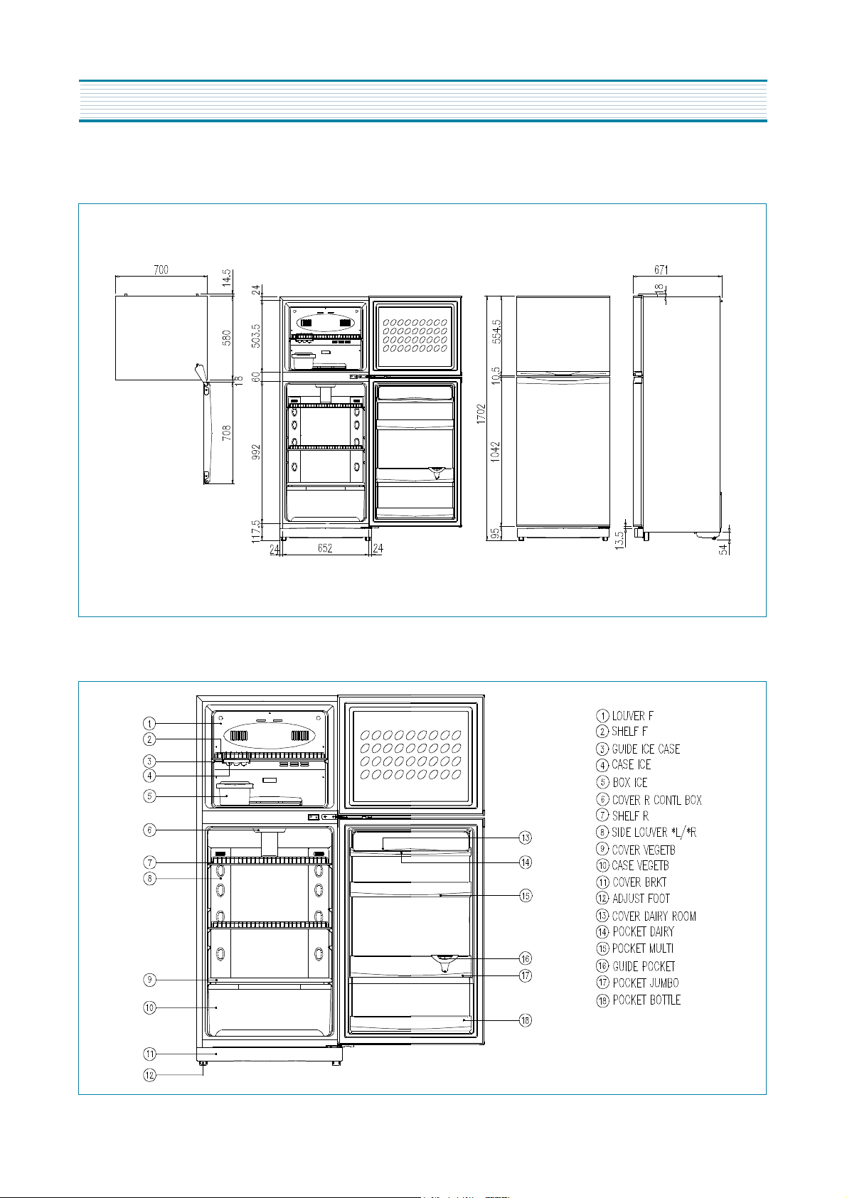
3. FR-4502K
1) EXTERNAL SIZE
2) NAME OF PARTS
?
5
EXTERNAM VICE
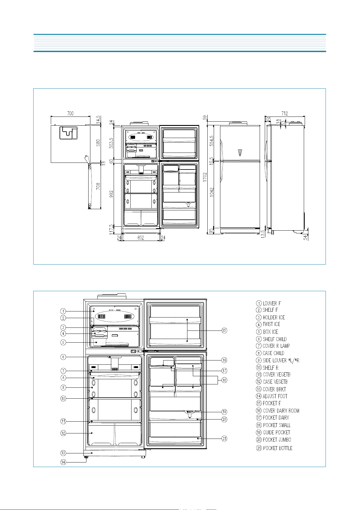
4. FR-4502N
1) EXTERNAL SIZE
2) NAME OF PARTS
?
6
EXTERNAM VICE
5. FR-4503N
1) EXTERNAL SIZE
2) NAME OF PARTS
?
7
EXTERNAM VICE
6. FR-4504K
1) EXTERNAL SIZE
2) NAME OF PARTS
?
8
EXTERNAM VICE
7. FR-4505K
1) EXTERNAL SIZE
2) NAME OF PARTS
?
9
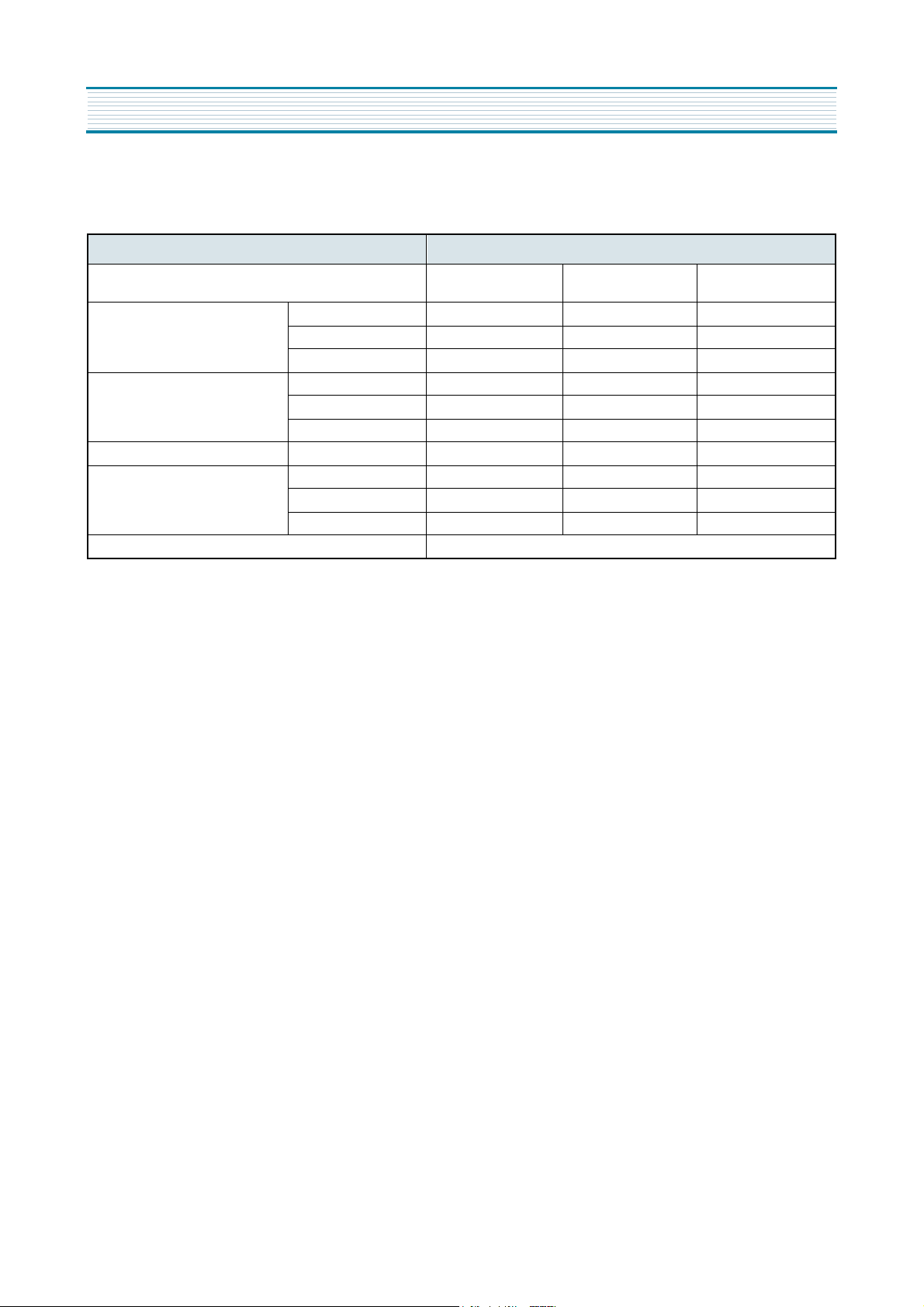
SPECIFICATIONS
1. OUTLINE
DIVISION CONTENTS
MODEL NAME
FR-4501K,FR-4502K
FR-4504K,FR-4505K
FR-450N,FR-4502N FR-4503N
USABLE CAPACITY
FREEZER 101ߧ 101ߧ 101ߧ
REFRIGERATOR 273ߧ 273ߧ 273ߧ
TOTAL 374ߧ 374ߧ 374ߧ
EXTERNAL DIMENSION
WIDHT 708mm 710.5mm 710.5mm
DEPTH 671mm 671mm 712mm
HEIGHT 1715mm 1759mm 1759mm
REFRIGERANT R134a 90g 90g 90g
COOLING & CONTROL SYSTEM
COOLING SYSTEM Fan Cooling System Fan Cooling System Fan Cooling System
DEFROST SYSTEM Fin Evaporator Forced Fin Evaporator Forced Fin Evaporator Forced
DEFROST CONTROL Automatic Start & Stop Automatic Start & Stop Automatic Start & Stop
NET WEIGHT (kg)

15
SPECIFICATIONS
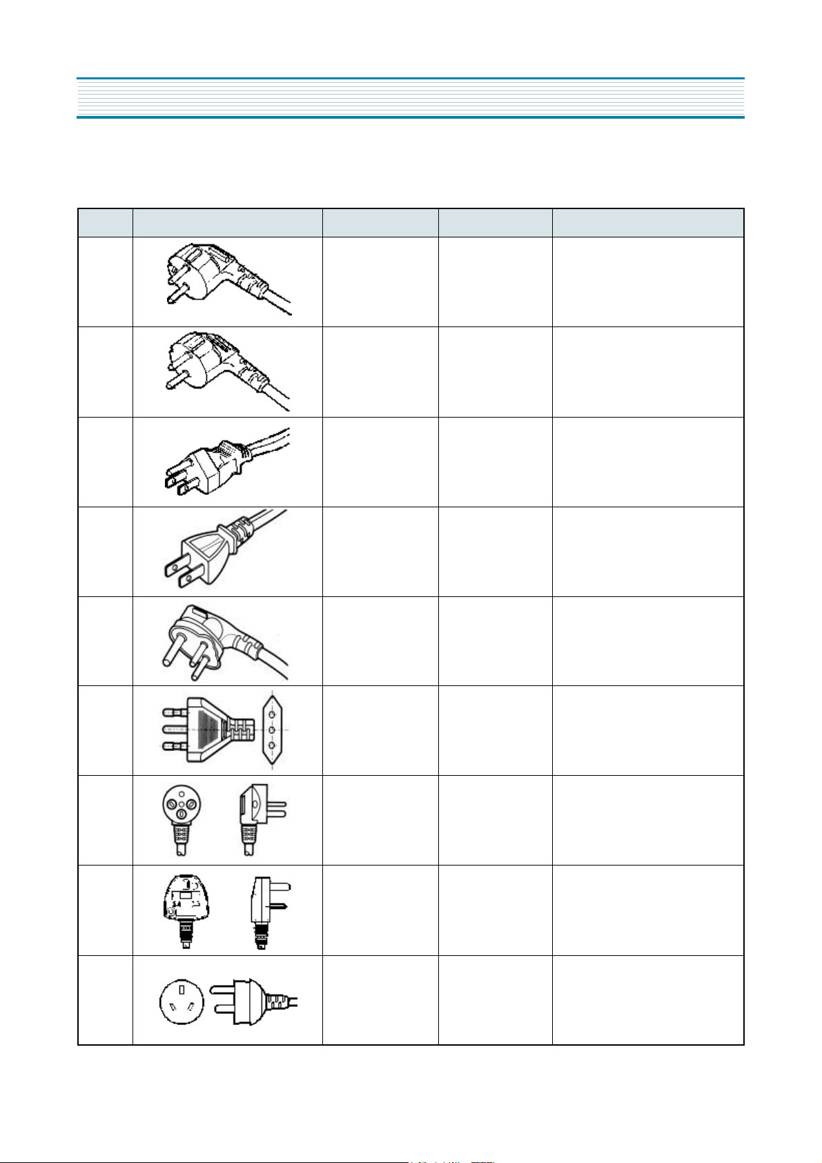
3. POWER CORD
NO SHAPE OF POWER CORD PART CODE DESCRIPTION REMARK
1 3011315000 CP-2PIN For european country
2 3010097000 CP-2PIN For other country
3 4006D17101 KP-30 For America & El Salvador
4 3010096800 KP-211 For Japan & Taiwan
5 3011300801 BP-3PIN
6 3011303010 # 267 For Chile
7 3011315310 For Israel
8 3011303050 BS-1363A
"For U.K, Middle Asia Singapore &
Malaysia"
9 3011301200 KP-551/550 For China & Australia
16
OPERATION AND FUNCTIONS
NO
CONTROL
FUNCTION
CONTROL
OBJECTS
CONTENTS REMARK
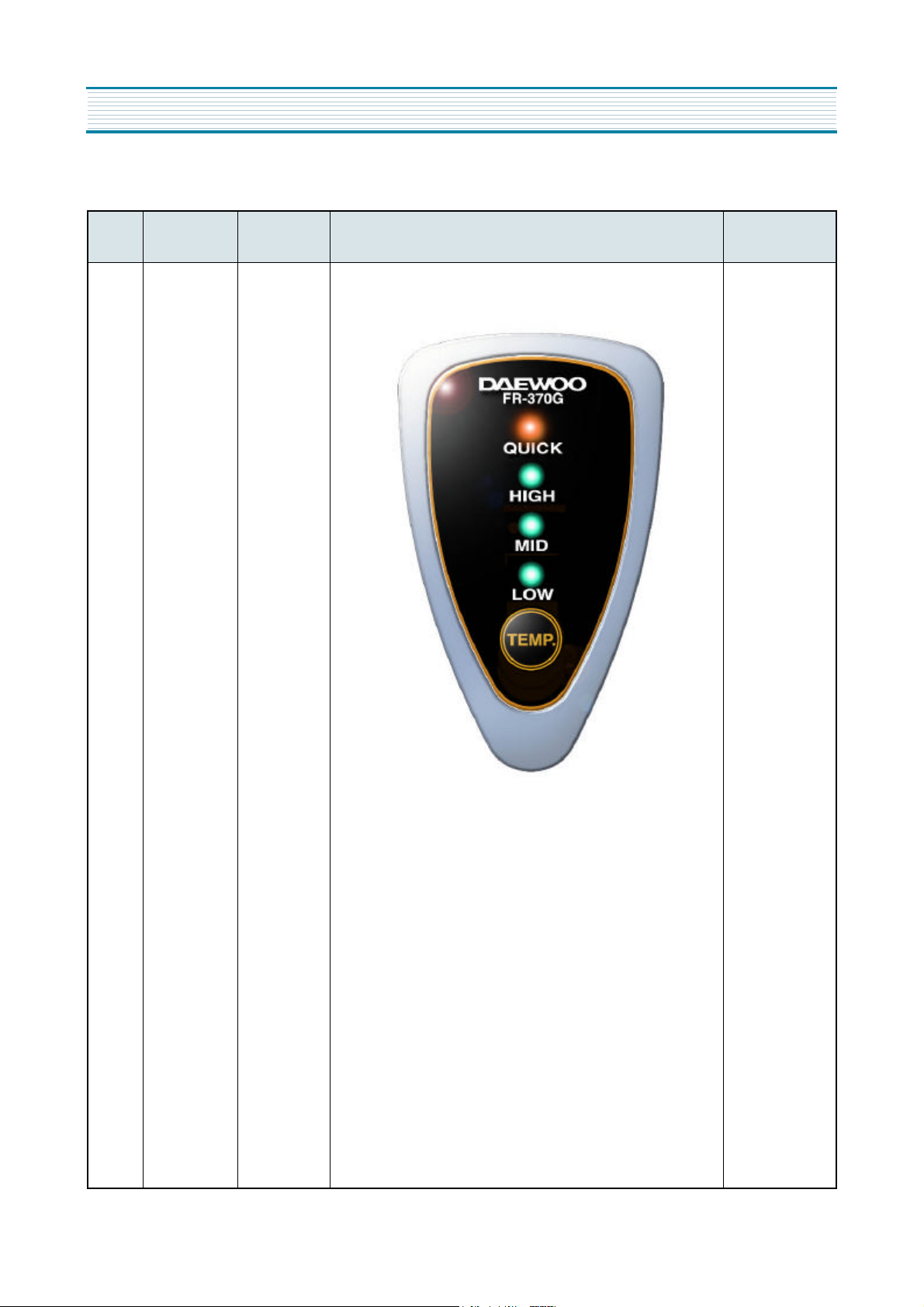
1 Display LED
1.TEMP BUTTON
1) Temperature of Refrigerator can be controlled as changin
control mode according to customer's desire.
2) Initial mode is "Mid" and whenever pressing TEMP buton,
control mode proceeds as follows.
Low -> Mid -> High -> Quick -> Low
3) If TEMP.button is pressed, control mode is set in 3 Sec.
2.QUICK MODE
1) If QUICK mode is set by TEMP.button, QUICK LED is on.
2) Maximum time of QUICK mode is 40 min.
3) If Refrigerator sensor (R-S) is below -3.0°C in QUICK mode,
QUICK mode can be finished immediately within 40min.
4) If QUICK mode is finished, it returns to the dial mode before
QUICK mode.
17
OPERATION AND FUNCTIONS
NO
CONTROL
FUNCTION
CONTROL
OBJECTS
CONTENTS REMARK
2 Control of
Temp
COMP
F-FAN
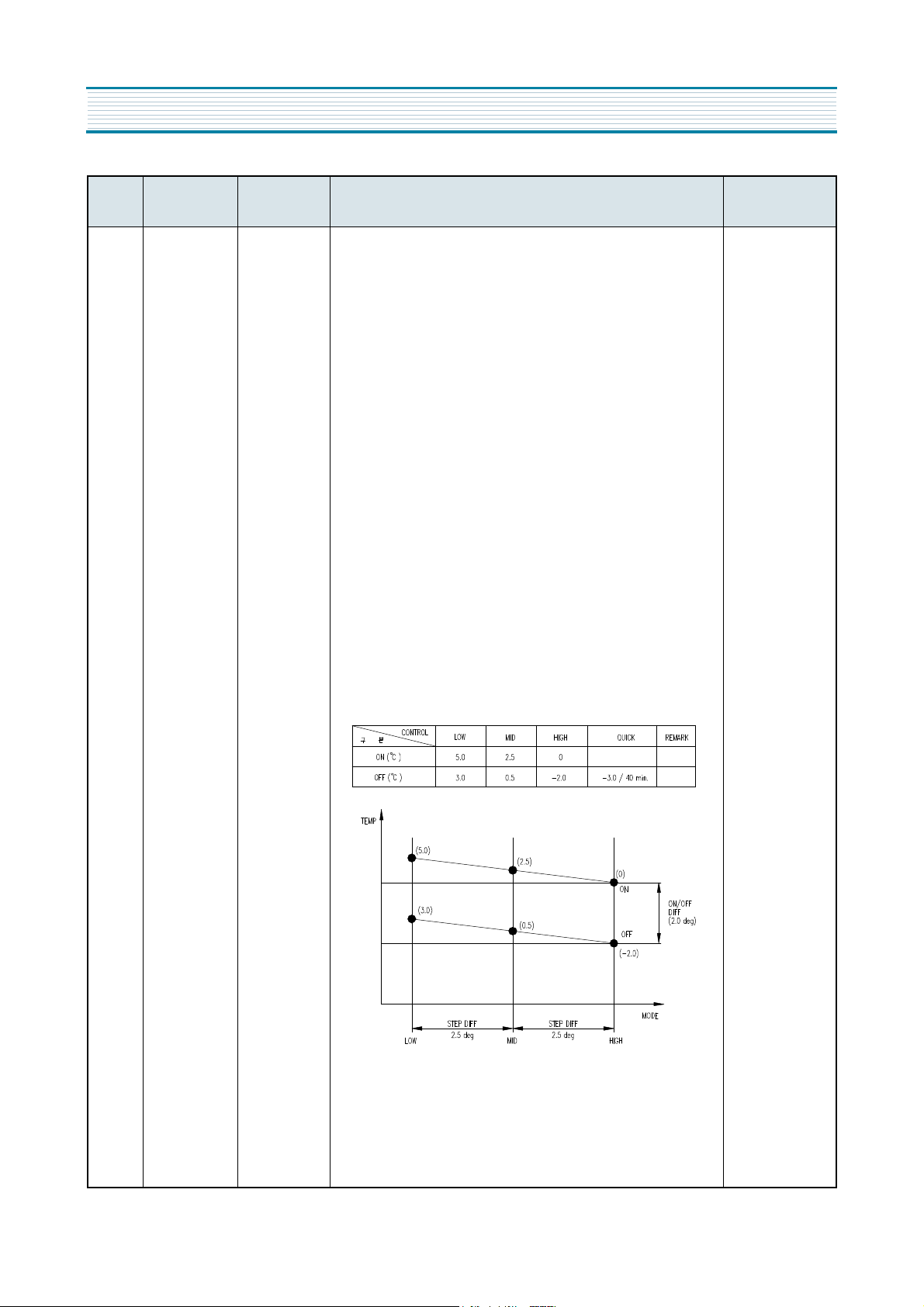
1. How to control Temperature of Refrigerator
1) Whenever TEMP.button is pressed, control mode is circulated
as follows:
LOW -> MID -> HIGH -> QUICK -> LOW
2) LEDs will indicate control mode according to TEMP.button.
3) Comp and F-fan are controlled by R-Sensor.
2. ON/OFF point of each control mode
1) Comp and F-fan are controlled ON/OFF point of each control
mode.
( ON/OFF point of R-SENSOR )
2) F-FAN is delayed for 1 min. after COMP is ON/OFF.
3) ON/OFF DIFF. Of Refrigerator = 2.0 deg.
4) STEP DIFF. Of Refrigerator = 2.5 deg.
18
OPERATION AND FUNCTIONS
NO
CONTROL
FUNCTION
CONTROL
OBJECTS
CONTENTS REMARK
3 Defrost
Period
Defrost mode 1. Determination of Defrosting Period
1) Total Run-tim of Comp : 10,11,12,13,14,15 hours
2) Run-ratio of Comp : over 80%
3) Total times of Door opening : over 3 times
4) Total time (Comp On + Comp Off): 60 hours
2. Explanation
1) Derosting starts with the following conditions, in case total
comp-run time passes 9 hours
- when an Error occurs
- when running-rate of Comp is more than 80%
- when total Door-opening times is more than 3 times
2) Defrosting starts unconditionally at each hour after total
Comp-run time passes 9 hours if terms of 1) is occurred.
3) Defrosting starts immediately when Total run-time is more than
15hours under the condition of 1),2) is not satisfied.
4) Defrosting starts immediately when Total time is more than 15
hours under the condition of 1),2),3) is not satisfied.
4 Defrosting
Mode
Comp Fan
Heater
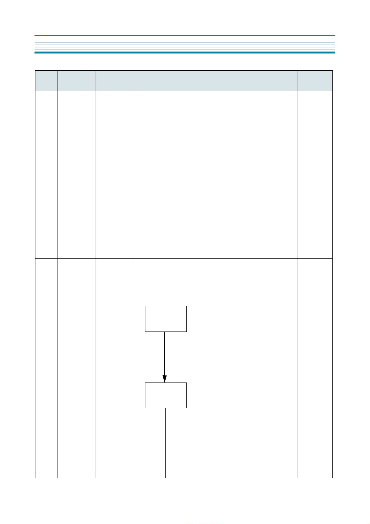
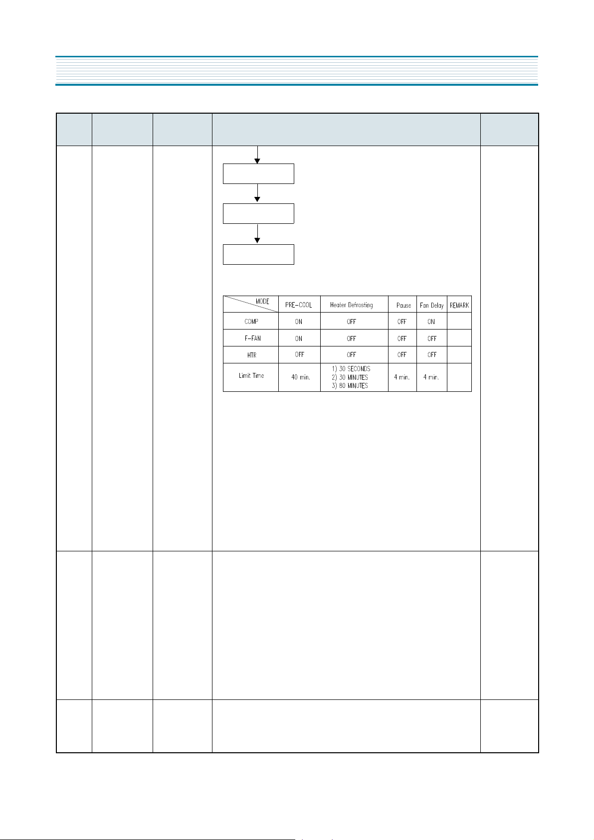
1. Normal Defrosting
1) Starting by Defrosting Period
2) How to proceed : using heater
3) Defrosting mode and procedure
¨ç
Proceeding time: 40min
¨è
Control Object: Comp On
FAN ON,Heater Off
¨é
Terminating Condition:
if R-sensor temp. is below
-4°C even though
it passes 40 min.
¨ê
Limit Proceeding time
- 30 min.: D1 ERROR
D-Sensor disconnection/
short-curcuit
- 80 min.: F3 ERROR
Normal Control state
¨ë
Control Object: Comp Off,
FAN OFF,Heater On
¨ì
Terminating Condition:
if D-sensor temp. is over 10°C
PRE-
COOL
HEATER
Defrosting
19
OPERATION AND FUNCTIONS
NO
CONTROL
FUNCTION
CONTROL
OBJECTS
CONTENTS REMARK
¨ç Proceeding time: 4min
¨è Control Object: Comp Off,
FAN Off,Heater Off
¨çProceeding time: 4min
¨è Control Object: Comp On,
FAN Off, Heater Off
4) Output Control and Limit Time of each Defrosting mode
2.Forced Defrosting
1) Start: Defrosting starts by pressing Temp.control s/w five times in a
row when door is open.
2) End : No function
3) Process: using Heater
4) Defrosting mode and procedure:
same as Normal Defrosting( Skip pre-cool mode )
5) Heater is On during initial 30 seconds without conserning D-sensor
Temp.
5 Initial
Defrosting
COMP
F-FAN HTR
1. If D-sensor temp. *3.5°C in the initial power input, normal defrosting
mode begins without concerning Comp run-time ( include Pre-cool
mode )
2. Defrosting begins after doing Comp restart prevention function with
dealy for six min. in initial defrosting mode.
3. Comp will be On imme
diately if D-sensor temp. ]3.5°C in initial power input.
( No dealy for six min. )
6 Prevention of
Comp
COMP
F-FAN
1. In order to protect Comp after Comp ioff, it won’t re-start for six min.
though R-sensor becomes On.
PAUSE
Fan Delay
Normal Run
20
OPERATION AND FUNCTIONS
NO
CONTROL
FUNCTION
CONTROL
OBJECTS
CONTENTS REMARK
7 Error Display LED 1. ERROR DISPLAY
1) How to start: Push Temp. control s/w for five secs. In Continuous
-run mode.
2) How to end: It returns automatically after 20 secs in Error mode with
out concering Error.
2. DISPLAY AND HOW TO CONTROL
1) D1 ERROR
- Starting Condition: D-Sensor Disconneciton/Shortcircuit
- Display: Flickering "LOW" LED
- How to control: return to limit time (30min.)
2) R1 ERROR- Starting Condition: R-Sensor Discon-nection/Shortcir-
cuit
- Display: Flickering "MID" LED
- How to control: control continuously Comp,F-fan to be On(30min.)
and Off(30min.)
3) F3 ERROR - Starting Condition: Heater 80min.
ends
- Display: Flickering "HIGH" LED
- How to control: impossible to control in case of Heater
Defrostng,Temp.Fuse problem,HTR Disconnection
4) C1 ERROR- Starting Condition: Even if Comp has run for 120min.
continuously,when D-sensor is¡Ã-5°C
- Display: Flickering "QUICK" LED
- How to control: impossible to contro in case of Cycle error
5) If there's no error when it enters Error mode, All LEDs will be OFF.
HTR disconnection.
8 Time Delay of
Electric
Devices
1. F-FAN time delay in Comp On/Off
1) During normal running: F-fan will be On/Off 1 min. after Comp On/Off
2) When initial power input: F-Fan will be ON 4 mins. After Comp On
2. F-FAN TIME DELAY BY DOOR S/W
1) After 6 mins.of initial power input
OPEN DR S/W -> CLOSE : F-fan work delay for 20 secs.
2) Before 6 mins.of initial power input
OPEN DR S/W -> CLOSE : F-fan work for 20 secs. immediately.
3) when it has nothing to do with Initial power input.
OPEN DR S/W ->CLOSE: F-fan changes into be Off. immediately.
 Loading...