


RNR30NIC
Dacor RNR30NIC, RNR30NFC, RNR30NIFC, RNR30NIS, RNR30NS Installation Guide
...
Installation Instructions
Renaissance® Electric Range
with induction cooktop
Models: RNR30NC[-C], RNR30NFC[-C], RNR30NIC[-C] and RNR30NIFC[-C]
RNR30NS[-C], RNR30NFS[-C], RNR30NIS[-C] and RNR30NIFS[-C]
Part No. 108559 Rev. C

Table of Contents
Important Safety Instructions .....................................................1
Important Information About Safety Instructions.........................1
Safety Symbols in this Manual ...................................................1
General Safety Precautions
Product Specifications ................................................................3
Electrical Requirements ..............................................................3
Product Dimensions ....................................................................4
Installation Specifications
Cabinet Layout ............................................................................5
Installation Instructions ...............................................................8
Verify the Package Contents ......................................................8
IMPORTANT:
• Installer: In the interest of safety and to minimize problems, read these installation instructions completely and carefully before you
begin the installation process. Leave these installation instructions with the customer.
• Customer: Keep these installation instructions for future reference and the local building inspector’s use.
........................................................2
...........................................................5
Installing the Anti-Tip Bracket
Backguard Installation ..............................................................10
Downdraft Vent Installation .......................................................10
Removing the Oven Door
Electrical Connection ................................................................10
Side Panel Removal ................................................................16
Installing the Range ..................................................................16
Re-installing the Oven Door
Verifying Proper Operation .......................................................17
Installation Checklist .................................................................18
.....................................................8
.........................................................10
.....................................................17
Customer Service Information
If You Need Help...
If you have questions or problems with installation, contact your
Dacor dealer or the Dacor Customer Service Team. For repairs
to Dacor appliances under warranty call the Dacor Distinctive
Service line. Whenever you call, have the model and serial
number of the appliance ready. The model and serial number are
printed on the product data label.
Dacor Customer Service
Phone: (800) 793-0093, extension 2813 (U.S.A. and Canada)
Monday — Friday 6:00
Web site: www.dacor.com
Dacor Distinctive Service (for repairs under warranty only)
Phone: (800) 793-0093, extension 2822 (U.S.A. and Canada)
Monday — Friday 6:00
a.m. to 5:00 p.m. Pacific Time
a.m. to 5:00 p.m. Pacific Time
Product Data Label Location
The product data label can be seen through the grill below the
control panel, on the right side.
Product data label
(view through right side
of grate with flashlight)
Model Identification
Model Configuration Handle Type Electrical Connection
RNR30Nx*
RNR30Nx*-C
RNR30NFx*
RNR30NFx*-C
RNR30NIx*
RNR30NIx*-C
RNR30NIFx*
RNR30NIFx*-C
* Finish: C = custom color, S = Stainless steel
All specifications subject to change without notice. Dacor
Freestanding, (full size side panels),
6-inch backguard standard
Freestanding, (full size side panels),
6-inch backguard standard
Freestanding, (full size side panels),
6-inch backguard standard
Freestanding, (full size side panels),
6-inch backguard standard
Built-in/Slide-in (3” removable side
panels), backguard optional
Built-in/Slide-in (3” removable side
panels), backguard optional
Built-in/Slide-in (3” removable side
panels), backguard optional
Built-in/Slide-in (3” removable side
panels), backguard optional
Mounted on
outside of door
Mounted on
outside of door
Flush handle,
integrated in door
Flush handle,
integrated in door
Mounted on
outside of door
Mounted on
outside of door
Flush handle,
integrated in door
Flush handle,
integrated in door
®
assumes no liability for changes to specifications.
© 2014 Dacor, all rights reserved.
Power cord not included. Not for
installation in Canada.
Cord connected, for installation in Canada
and U.S.A., where local codes permit.
Power cord not included. Not for
installation in Canada.
Cord connected, for installation in Canada
and U.S.A., where local codes permit.
Power cord not included. May be installed
in Canada and U.S.A.
Cord connected, for installation in Canada
and U.S.A., where local codes permit.
Power cord not included. May be installed
in Canada and U.S.A.
Cord connected, for installation in Canada
and U.S.A., where local codes permit.
Important Safety Instructions
Important Information About
Safety Instructions
The Important Safety Instructions and warnings in this manual
are not meant to cover all possible problems and conditions
that can occur. Use common sense and caution when installing,
maintaining or operating this or any other appliance.
Always contact the Dacor Customer Service Team about problems
and conditions that you do not understand.
DANGER
For your safety:
• Do not store or use gasoline or other flammable vapors and
liquids in the vicinity of this or any other appliance.
• Do not obstruct the flow of ventilation air to the unit.
• Keep the area around the appliance clear and free from
combustible material.
WARNING
Persons with a pacemaker or other medical device should use
caution when standing near an induction cooktop when it is
in use. The electromagnetic field generated by an induction
cooktop may affect operation of a pacemaker or other medical
device. Consult your doctor or medical device manufacturer
about your particular situation.
Safety Symbols in this Manual
DANGER
Immediate hazards that WILL result in severe personal injury or
death.
WARNING
Hazards or unsafe practices that COULD result in severe
personal injury or death.
CAUTION
Hazards or unsafe practices that COULD result in minor
personal injury or property damage.
WARNING
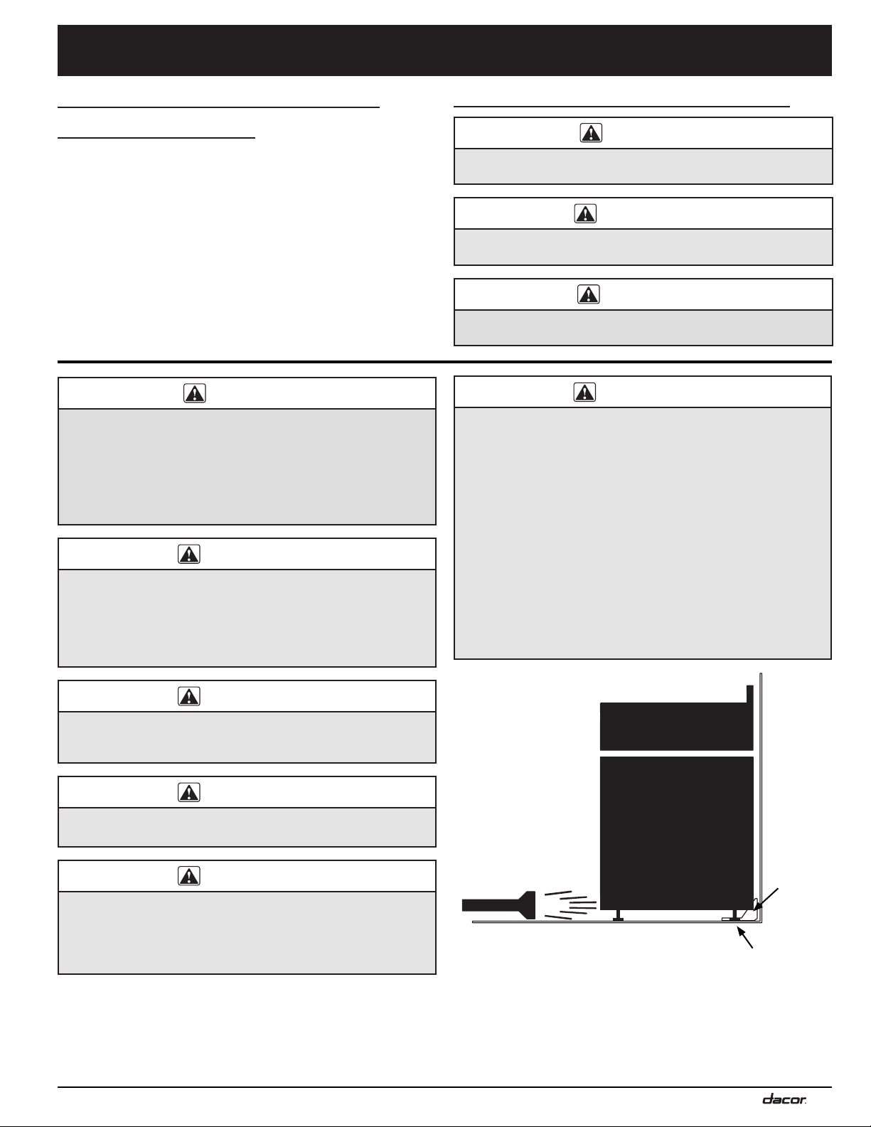
Tip-over hazard:
• A child or adult can tip the range and be killed.
• Attach the anti-tip bracket to the floor or wall as directed
in these installation instructions. Engage the floor or wall
mounted anti-tip bracket by sliding the rear leg on the range
into it according to these installation instructions. Using
a flashlight, be sure that the anti-tip bracket engages the
range’s rear leg as shown below.
• After moving the range, be sure to re-engage the rear leg
into the anti-tip bracket as shown below.
• See the anti-tip bracket installation instructions in this guide
for further details.
• Failure to follow these instructions can result in death or
serious burns to children or adults.
WARNING
If the information in this manual is not followed exactly, a fire or
explosion may result causing property damage, personal injury
or death.
WARNING
NEVER use this appliance as a space heater to heat or warm
the room. Doing so may result in overheating of the appliance.
WARNING
NEVER cover any slots, holes or passages in the oven bottom
or cover an entire rack with materials such as aluminum foil.
Doing so blocks air flow through the oven and may cause a fire
hazard. Aluminum foil linings may also trap heat, causing a fire
hazard.
READ AND SAVE THESE INSTRUCTIONS
Anti-tip
bracket
Rear leg
1
Important Safety Instructions
General Safety Precautions
To reduce the risk of fire, explosion, electric shock, serious injury or death when installing or using this appliance, follow basic safety
precautions, including the following:
WARNING
• Read all instructions before using the appliance.
• Keep packaging materials away from children. Plastic
sheets and bags can cause suffocation.
• If you receive a damaged product, immediately contact
your dealer or builder. Do not install or use a damaged
appliance.
• Improper installation, adjustment, alteration, service
or maintenance can cause personal injury or property
damage. Refer to these instructions and the accompanying
use and care manual. For assistance or additional
information, consult a qualified installer, service agency or
dealer.
• This appliance must be properly installed and grounded by
a qualified installer or service agency according to these
installation instructions prior to use. The installer must
show the customer the location of the circuit breaker panel
or fuse box so that they know where and how to turn off
electric power to the appliance. Dacor is not responsible for
service required to correct a faulty installation. The owner
is responsible to make sure this appliance is properly
installed.
• DO NOT TOUCH THE SURFACES OF THE OVEN OR
COOKTOP DURING OR IMMEDIATELY AFTER USE.
• This appliance is not approved for installation in a mobile
home or recreational vehicle.
• This appliance must not be used in combination with
surface (countertop) ventilation systems. The use of an
overhead hood, or Dacor downdraft vent is recommended
for ventilation.
• Disconnect the electrical supply before installing or
servicing the appliance.
• Install or locate this appliance only in accordance with
these installation instructions.
• Before performing any type of service or installation, make
sure that the power to the appliance is turned off at the
circuit breaker panel or fuse box.
• Use this appliance only for its intended use as described in
this manual. Do not use corrosive chemicals or vapors with
this appliance. This type of appliance is not designed for
industrial or laboratory use.
• Do not leave children or pets alone or unattended in the
area around the range. Do not allow children to play with
the controls, pull on the handle, or touch other parts of the
range.
• Do not store items of interest to children on top of or
above the range. Children could be burned or injured while
climbing on the appliance.
• Some products, such as whole eggs, and sealed
containers, such as closed glass jars, may explode and
should not be heated on this cooktop.
• Clean the cooktop thoroughly before operating it for the first
time.
WARNING
• NEVER block or cover any slots, holes or passages
anywhere inside the oven or on the outside of the range or
cover an oven rack with materials such as aluminum foil.
Doing so blocks airflow through the oven and cooktop and
may create fire hazard. See the Getting to Know Your Range
section of the use and care manual for the location of the
various air holes (slots).
• Keep flammable items, such as paper, cardboard, plastic
and cloth away from the elements and other hot surfaces.
Do not place such items in the oven. Do not allow pot
holders to touch hot surfaces.
• Do not wear loose or hanging apparel while using the range.
Do not allow clothing to come into contact with the interior of
the oven or the cooktop and surrounding areas during and
immediately after use.
• Do not use the oven for storage.
• Do not touch the outside surfaces of the range during the
self-clean cycle. They will be hot. Venting from the oven may
cause the cooktop and backguard to become hot.
• For your safety, do not use the oven to cook without the
convection filter installed. When the filter is not installed, the
spinning fan blades at the back of the oven are exposed.
• Non-stick coatings, when heated, can be harmful to birds.
Remove birds to a separate, well-ventilated room during
cooking.
• To prevent damage, remove the meat probe from the oven
when it is not being used.
• Do not line the oven with aluminum foil or other materials.
These items can melt or burn up during self-cleaning and
cause permanent damage to the appliance.
• Do not leave metal objects, such as aluminum foil, the meat
probe, cookie sheets, etc. on the bottom of the oven.
• Objects left on the bottom of the oven could damage the
bake element. In addition, the objects themselves could be
damaged.
• On some ovens, the bake and broil elements are behind
glass panels on the floor and ceiling of the oven chamber.
Do not cover these glass panels with cookie sheets,
aluminum foil, pots, pans, etc. Covering them could cause
the heating elements to over-heat, damaging the oven.
2
Product Specifications
WARNING
IMPORTANT: Observe all governing codes and ordinances
during planning and installation. Contact your local building
department for further information.
Electrical Requirements (All models
numbers except those ending with -C)
It is the owner’s responsibility to ensure that a licensed electrician
performs the installation of the power supply for this appliance.
The electrical installation, including minimum supply wire size,
must comply with the National Electric Code ANSI/NFPA 70 (latest
revision) and local codes and ordinances. A copy of this standard
may be obtained from:
National Fire Protection Association
1 Batterymarch Park
Quincy, Massachusetts 02269-9101
The correct voltage, frequency and amperage must be supplied
to the appliance from a dedicated, grounded, single phase circuit
that is protected by a properly sized circuit breaker or time-delay
fuse. If a time-delay fuse is utilized, fuse both sides of the line (L1
and L2).
Electrical Specifications
Circuit Requirements Total Connected Load
240 Vac 60 Hz, 4-wire*, 50 Amp. 11.5 kW (48.0 Amp.)
* Two 120 Vac hot (L1 and L2), one neutral (N1) and one ground.
The above electrical specifications are for reference only. See the
product data label for exact specifications. See inside cover for
location.
• The wiring needs to be long enough to allow the range to be
pulled out for service, while remaining connected.
• The wiring connected to the range must:
◊ Meet NEMA standards and have a minimum rating of
250 Volts @ 50 Amp.
◊ Include a strain relief.
◊ Be terminated by tinned leads, closed loop terminals or
open ended spade lugs with upturned ends.
◊ Connect to a junction box or receptacle installed by a
licensed electrician.
The appliance may be connected one of the following ways:
• Using conduit:
◊ A 4-wire conduit connected to a 4-wire junction box, or
◊ A 3-wire conduit (where local code permits) connected to
a 3-wire junction box.
Suggested conduit wiring color code: black, white, red and
green.
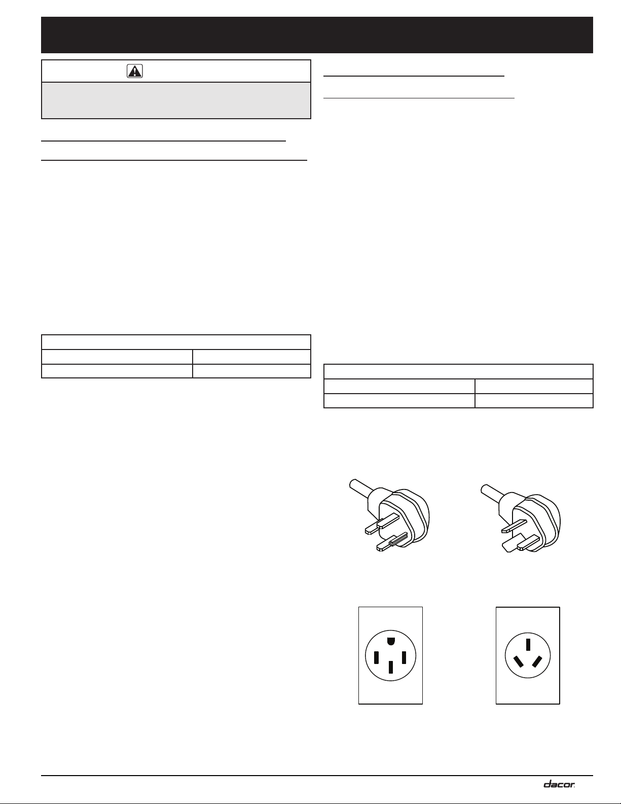
• Using an appliance cord:
◊ A 4-wire appliance cord equipped with a NEMA 14-50P
plug connected to a NEMA 14-50R receptacle, or
◊ A 3-wire appliance cord (where local code permits)
equipped with a NEMA 10-50P plug connected to a
NEMA 10-50R receptacle.
Appliance cord plug must be UL listed type SRD or SRDT.
Electrical Requirements
(Models Ending with -C)
Range models RNR30Nx-C, RNR30NFx-C, RNR30NIx-C and
RNR30NIFx-C come with a factory installed 4-wire appliance cord
with NEMA 14-50P plug.
• For freestanding ranges installed in Canada, a factory
installed 4-wire appliance cord with NEMA 14-50P plug is
required, without modification. For slide-in ranges installed in
Canada and all ranges installed outside of Canada, the 4-wire
appliance cord configuration (-C type) is optional and may be
utilized where local codes permit.
• The NEMA 14-50P plug is designed to plug directly into
a NEMA 14-50R electrical receptacle. It is the owner’s
responsibility to ensure that the required 4-wire electrical
outlet compatible with the power cord is installed by a
licensed electrician as specified below prior to range
installation. The electrical outlet installation, including
minimum supply wire size and grounding, must be in
accordance with all governing codes and ordinances.
• The correct voltage, frequency and amperage must be
supplied to the appliance from a separate, grounded, circuit
that is protected by a properly sized circuit breaker or time
delay fuse. If a fuse is utilized, fuse both sides of the line (L1
and L2). Refer to the ratings on the product data label.
Electrical Specifications
Circuit Requirements Total Connected Load
240 Vac 60 Hz, 4-wire*, 50 Amp. 11.5 kW (48.0 Amp.)
* Two 120 Vac hot (L1 and L2), one neutral (N1) and one ground.
The ratings above are for reference only - refer to the product
data label (see inside cover).
NEMA 14-50P Plug NEMA 10-50P Plug
NEMA 14-50R Receptacle NEMA 10-50R Receptacle
3

1” (2.5 cm)
Front of open door
Front of handle
Front panel
Rear of front panel
Backguard thickness
External handle
shown, some models
have integral handle
(see inside cover)
6” (15.2 cm) backguard*
Product width:
29 15/16” (76.0 cm)
35”
(88.9 cm)
to
37”
(94.0 cm)
A
B
C
D
RNR30NI[F]S:
3/8” (9.5 mm)
thick top trim
RNR30N[F]S:
full stainless
steel side panels
RNR30NI[F]S:
3” (7.6 cm)
partial stainless
steel side panels
(removable)
Product Dimensions
Product tolerances: ±1/16” (±1.6 mm), unless otherwise stated
Product Specifications
Dimension
Dimension RNR30Nx RNR30NIx
Available Backguard*
Part Number Description Compatibility
ADRB30E06
6 inches
high
Standard on models RNR30Nx, RNR30NFx
Optional on models RNR30NIx, RNR30NIFx
RNR30Nx
RNR30NFx
A
C
D
B
46 1/4”
(117.5 cm)
25 1/2”
(64.8 cm)
23 3/8”
(59.4 cm)
27 7/8”
(70.8 cm)
RNR30NIx
RNR30NIFx
46 1/16”
(117.0 cm)
25 5/16”
(64.3 cm)
23 3/16”
(58.9 cm)
27 11/16”
(70.3 cm)
4
**Models RNR30NIx and RNR30NIFx come equipped from the factory with a
flat stainless steel trim piece in place of a backguard. A 6 inch backguard may
be purchased as an optional accessory. Add an additional 1/16 inch to the
depth dimensions above when installing a backguard on models RNR30NIx and
RNR30NIFx.
The trim on models RNR30Nx and RNR30NFx are not compatible with a downdraft
vent.
Models RNR30NIx and RNR30NIFx are compatible with Dacor downdraft vent
model ERV3015 only.
x = Finish: C for custom color, S for Stainless
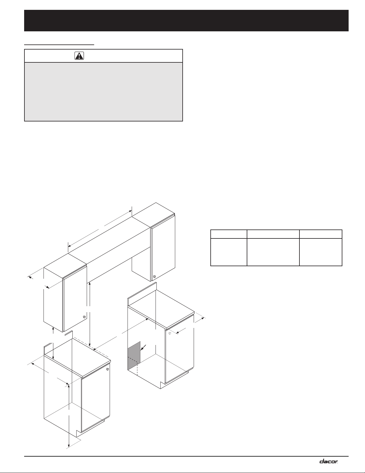
Installation Specifications
13” (33.0 cm)
Cabinet Layout
WARNING
• Observe all governing codes and ordinances during
planning and installation. Contact your local building
department for further information.
• All minimum cabinet/countertop clearances shown on the
following pages must be met or exceeded.
• To eliminate the risk of burns or fire by reaching over heated
surface units, cabinet storage space located above surface
units should be avoided.
• The shaded areas shown below denote the location of the
electrical junction box/receptacle. This is the suggested
location. For replacement purposes, the location of the
existing electrical supply may be utilized provided that it does
not interfere with the sides or rear of the range. Verify that the
electrical service meets local building codes.
• Access to the remote circuit breaker panel/fuse box, with the
range in place and operating, must also be allowed for in the
installation.
Cutout tolerances: +1/16” (+1.6 mm), -0,
unless otherwise stated.
• The electrical junction box/receptacle must be located so
that it does not interfere with the range when it is installed
and under operation. In addition, the junction box/receptacle
must be located so the range can be removed for service and
remain connected to power.
Cabinet and Countertop Preparation
• To reduce the risk of personal injury and to reduce
accumulated smoke in the room, Dacor strongly recommends
installing a range hood. A range hood should project
horizontally a minimum of five (5) inches beyond the face of
the cabinets. If installing a range hood, see the range hood
specifications for minimum clearances. If cabinet storage
space is to be provided directly above the range, the risk of
personal injury may be reduced by installing a range hood.
• The range may be installed flush to the rear wall. Dacor
recommends installing a non-combustible material on the rear
wall above the range and up to the range hood or cabinet,
whichever is lower.
• Any openings in the wall behind the appliance and in the floor
under the appliance must be sealed.
4
max.
18” (45.7 cm)
min.
Note 2
B
A* B C*
36” (91.4 cm)
30 1/16” min.
(76.3 cm)
recommended
30” (76.2 cm)
min.
*For self rimming installations, see required dimensions
for “A” and “C” on the following pages.
Non-combustible
surface along
back wall
recommended
Suggested
location of
3
utilities
Top of
finished
counter
Note 5
1
30” (76.2 cm) min. vertical clearance from top of the
cooking surface to bottom of uncovered wood or metal
Note 1
4
A
cabinet. 24” (61 cm) min. clearance if bottom of wood or
metal cabinets are protected by not less than 1/4“ (0.6
cm) flame retardant millboard covered with no less than
No. 28 MSG sheet steel 0.015” (0.04 cm) stainless steel,
or 0.024” (0.06 cm) aluminum or 0.020” (0.05 cm) copper.
If installing a range hood, also check hood specifications
for minimum required clearances.
2
Cabinet/countertop depth is at discretion of the
customer but cabinet face SHALL NOT protrude further
C
than rear of front panel. See Product Dimensions.
3
Consult local code for requirements.
4
This specification not applicable for cabinets more than
a horizontal distance of 1” (2.6 cm) from edge of range.
5
Cabinet Dimensions
1” (2.6 cm) min. to combustible side walls above range
(both sides).
35” (88.9 cm)
min.
37” (94.0 cm)
max.
5

Installation Specifications
Rear wall or
countertop edge
countertop opening
29 1/4” (74.3 cm)
30 1/16” (76.2 cm)
cabinet opening
below countertop
below countertop
Cabinet face
Notch countertop
to width of cabinets
3/8” min. (9.5 mm)
countertop overhang
1” min. (2.6 cm)
to any combustibles
above counter both sides
20”
(50.8 cm)
to
23”
(58.4 cm)
20”
(50.8 cm)
Countertop front
Max.
overhang
1 5/8”
(4.1 cm)
Rear wall or
countertop edge
countertop opening
29 1/4” (74.3 cm)
30 1/16” (76.2 cm)
1
cabinet opening
below countertop
below countertop
Cabinet face
Notch countertop
to width of cabinets
3/8” min. (9.5 mm)
countertop overhang
1” min. (2.6 cm)
to any combustibles
above counter both sides
23”
(58.4 cm)
Max.
overhang
1 5/8”
(4.1 cm)
Countertop front
34 3/4”
to
36 7/8”
(see diagrams)
Countertop
1 5/8 (41.1 cm)
max. thickness
Cabinet Cutouts for Self-Rimming Installation (Models RNR30NIx and RNR30NIFx Only)
Cutout tolerances: +1/16” (+1.6 mm), -0, unless otherwise stated.
• The self-rimming installation of the RNR30NI[F]x range
creates a “built-in” look where the range trim overlaps
and rests on the countertop on both sides and in back.
• Observe all vertical cabinet clearances on page 5.
• On self-rimming installations when sliding the range into
position, it will stop when the rear of the control panel or
side panels contact the notches toward the front of the
countertop.
Top View - Slide-In, Self-Rimming Installation,
3” Side Panels Removed - Min. Required Cabinet Depth: 23 3/8”
3” Side Panels Installed - Cabinet Depths 20 3/8” to 23 3/8”
6
Top View - Slide-In, Self-Rimming Installation,
1
To create a “built-in look” on the front of the cabinet,
this dimension may be changed to 29 1/4” (74.3 cm),
with the width at the notches remaining 30 1/16”.
This configuration is only for models RNR30NIx and
RNR30NIFx with the side panels behind the door
removed.
 Loading...