


RNHP30
Dacor RNHP30, RNHP48, RNHP36, RNHE48, RNHE36 User Manual
...
Installation Instructions
Renaissance
®
Wall-Mount Range Hoods
Models RNHP30/36/48; Models RNHE30/36/48
Part No. 109172 Rev. B
APPROVED FOR USE WITH ALL DACOR
®
RANGES AND COOKTOPS.
TESTED IN ACCORDANCE WITH THE LATEST EDITION OF ANSI/UL 507
STANDARD FOR ELECTRIC FANS AND CAN/CSA-C22.2 NO. 115 STANDARD
FOR FANS AND VENTILATORS.

Important:
• Installer: For safety reasons and to minimize problems, read these Installation Instructions completely and carefully
before starting the installation process. Leave these installation instructions with the consumer.
Write the data-plate information (model no., serial no.) in the Use and Care Manual before you install the unit.
• Customer: Keep these Installation Instructions for reference and the local electrical inspector’s use.
If You Need Help…
…with questions or installation problems, contact your Dacor dealer or
the Dacor Customer-Service Team. For under-warranty repairs to Dacor
appliances, call the Dacor Distinctive Service line. When you call, be prepared
with the appliance’s model and serial number. (See the appliance’s data plate.)
Dacor Customer Service Team
Phone: (800) 793-0093 x2813 (USA, Canada)
Mon–Fri 6:00 a.m.–5:00 p.m. Pacific Time
Website: www.dacor.com
Dacor Distinctive Service (under-warranty repairs only)
Phone: (800) 793-0093 x2822 (USA, Canada)
Mon–Fri 6:00 a.m.–5:00 p.m. Pacific Time
Appliance Data Plate
This label contains the model and serial number, and electrical requirements.
The data plate is inside the hood above the filters on the chassis’ back wall.
(Remove the filters to view the data plate.)
All specifications are subject to change without notice. Dacor
assumes no liability for changes to specifications.
© 2016 Dacor, all rights reserved.
Planning the Ductwork ..................................................... 8
Preparing the Mounting Location ..................................... 9
Installation Instructions .................................................. 11
Marking the Centerlines .................................................11
Installing the Holding Brackets ........................................11
Rotating the Blower(s) for Rear Exhaust ....................... 12
Assembling the Filters .................................................... 14
Using the Dual to Single Transition Kit# AHT10 ............ 15
Hanging the Range Hood .............................................. 16
Hardwiring the Hood ...................................................... 17
Verifying the Setup ......................................................... 19
The Installation Checklist ............................................... 19
Wiring Diagrams .............................................................. 20
Table of Contents
Before You Begin...
Important Safety Instructions .......................................... 1
Important Information About Safety Instructions .............. 1
General Safety Precautions ............................................. 2
Product Specifications .................................................... 3
General Specifications ..................................................... 3
Weight Specifications ....................................................... 3
Dimensions ...................................................................... 4
Preparation and Setup ...................................................... 6
Parts List .......................................................................... 6
Needed Tools and Hardware ........................................... 6
Meeting Electrical Codes ................................................. 6
Installing the Electrical Source ......................................... 7
Meeting Installation Requirements ................................... 7
1
Important Information About
Safety Instructions
• The Important Safety Instructions and warnings in
these instructions are not meant to cover all possible
problems and conditions that can occur. Use common
sense and caution when installing, maintaining or oper-
ating this or any other appliance.
• Always contact the Dacor Customer Service Team
about problems and conditions that you don’t under-
stand.
Important Safety Instructions
Safety Symbols and Labels
DANGER
Immediate hazards that WILL result in severe personal
injury or death.
WARNING
Hazards or unsafe practices that COULD result in severe
personal injury or death.
CAUTION
Hazards or unsafe practices that MIGHT result in minor
personal injury or property damage.
DANGER
To avoid the possibility of explosion or fire, do not store or use combustible, flammable or explosive vapors and liquids
(such as gasoline) inside or in the vicinity of this or any other appliance. Also keep items that could explode, such as
aerosol cans away from cooktop burners, ovens and range hoods. Do not store flammable or explosive materials in
adjacent cabinets or areas.
WARNING
If the information in this manual is not followed exactly, a fire or explosion may result causing property damage, personal
injury or death.
WARNING
WARNING - TO REDUCE THE RISK OF FIRE, ELECTRIC SHOCK, OR INJURY TO PERSONS, OBSERVE THE
FOLLOWING:
a) Use this unit only in the manner intended by the manufacturer. If you have questions, contact the manufacturer.
b) Before servicing or cleaning unit, switch power off at service panel and lock the service disconnecting means
to prevent power from being switched on accidentally. When the service disconnecting means cannot be
locked, securely fasten a prominent warning device, such as a tag, to the service panel.
WARNING
WARNING – TO REDUCE THE RISK OF FIRE, ELECTRIC SHOCK, OR INJURY TO PERSONS, OBSERVE THE
FOLLOWING:
a) Installation work and electrical wiring must be done by qualified person(s) in accordance with all applicable
codes and standards, including fire-rated construction.
b) Sufficient air is needed for proper combustion and exhausting of gases through the flue(chimney) of fuel
burning equipment to prevent back drafting. Follow the heating equipment manufacturer’s guideline and safety
standards such as those published by the National Fire Protection Association (NFPA), and the American
Society for Heating, Refrigeration and Air Conditioning Engineers (ASHRAE), and the local code authorities.
c) When cutting or drilling into wall or ceiling, do not damage electrical wiring and other hidden utilities.
d) Ducted fans must always be vented to the outdoors.
READ AND SAVE THESE INSTRUCTIONS
2
Important Safety Instructions
• Use the hood only as outlined in this manual. Do NOT use the hood to vent hazardous/explosive materials or vapors. If you have questions,
contact Dacor (contact info on Pg. 1).
• If you receive a damaged product, immediately contact your dealer/builder. Do not install/use a damaged hood.
• Verify that the hood was properly installed and grounded by a qualified installer according to procedures in this guide. Have the installer show
you the fuse or junction box so you can turn the power ON/OFF as needed.
• Install or locate this appliance only in accordance with these installation instructions and the requirements specified by the manufacturer of the
cooktop or range. Improper installation, adjustment, alteration, service, or maintenance can cause serious personal injury or property damage.
• Do not install/repair/replace any part of the range hood unless specifically recommended by the procedures in this guide. A qualified service
technician should perform all other service. Contact the nearest Dacor authorized service representative at (800) 793-0093, or at www.dacor.
com for examination, repair or adjustment.
• Do not use an extension cord or adapter plug with this appliance.
• To avoid risk of electric shock:
- Before service is performed, switch power off at the fuse/junction box, and lock the electrical-panel door so power cannot be switched on
accidentally. If the electrical panel cannot be locked, securely fasten a prominent warning device (e.g., tag) to the panel.
- Before cleaning the hood, turn off the main power switch (Pg. 3).
• Read the Use and Care Manual completely before using the appliance. Clean the appliance only as instructed in the Use and Care Manual.
Use only the cleaners specified.
• Do not tamper with the controls.
• Never let the filters become blocked/clogged, or foreign objects (e.g., cigarettes, napkins) be sucked into the hood.
• To avoid a fire hazard:
- If the appliance is by a window, do not use window coverings that could blow over the cooking surface and hood.
- Use only metal ducting.
• Always run the hood fans when using your range/cooktop.
• Never let children:
- alone in the vicinity of an operating range/cooktop
- sit/stand on/play with your range/cooktop/hood; or store items of interest to children above/around these appliances.
- play with packaging materials; plastic bags can cause suffocation.
• The minimum vertical distance between the cooking surface and the bottom-most part of the hood must be at least 30” (76.2 cm). Consult the
instructions in this manual for the minimum vertical distance in your specific case.
• Do not attempt to use this appliance during a continuous power outage.
• To reduce risk of a grease fire:
- never leave the range/cooktop unattended at high settings; boil-overs cause smoking and greasy spill-overs that may ignite; heat oils
slowly on low/medium settings
- always turn the hood ON if cooking at high heat or when flambéing food (e.g., Crepes Suzette, Cherries Jubilee, Peppercorn Beef Flambé)
- clean ventilating fans frequently; do not let grease accumulate on the filter or other hood components
- always use cookware appropriate to the size of the surface element or grate.
• TO REDUCE RISK OF PERSONAL INJURY FROM A GREASE FIRE:
- CAREFULLY SMOTHER FLAMES with a close-fitting lid, cookie sheet, or metal tray, then turn off the burner. If the flames do not die
immediately, EVACUATE, THEN CALL THE FIRE DEPARTMENT.
- NEVER PICK UP A FLAMING PAN.
- DO NOT try to extinguish flames with water or wet dish cloths/towels; a violent steam explosion may result.
• (FOR GREASE FIRES) USE A FIRE EXTINGUISHER ONLY IF:
- you have a Class ABC extinguisher and know how to operate it
- the fire is small and contained in its area of origin
- the fire department is being called
- you can fight the fire with your back to an exit.
WARNING
To reduce the risk of fire, electric shock, serious injury, or death when using your range hood, follow basic safety precau-
tions, including these:
3
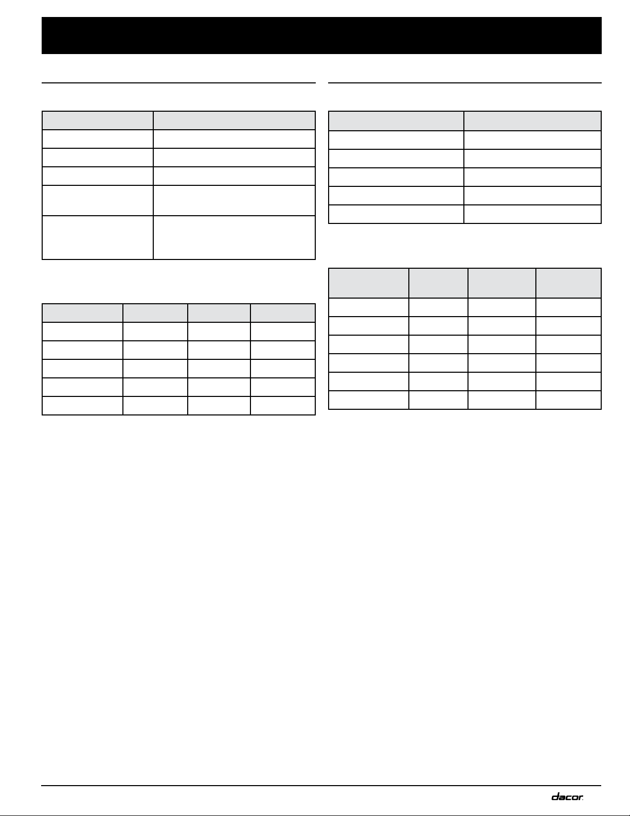
General Specifications
All Models: RNHP, RNHE
Features Description
Blower Speeds Four (4)
Filters Baffle style, dishwasher safe
Exhaust(s) 8-in. duct diameter
Total Connect Load
120V, 60 Hz, 9 Amp. Max.
(10.0 Amp Max. surge)
Lights
Dimmable LED: PAR16
E26/27; 120V, 7.5W (75W
Max. other bulbs)
Individual Models: RNHP, RNHE
Components 48 36 30
Lights 4 3 2
Filters 4 3 2
Blowers 2 1 1
Exhaust Vents 2 1 1
Blower Rating 1200 CFM 600 CFM 600 CFM
Product Specifications
Individual Models: RNHP, RNHE
Model Weight
3012 51 lbs. (23 kg)
3018, -3612 53 lbs. (24 kg)
3618 57 lbs. (26 kg)
4812 70 lbs. (32 kg)
4818 77 lbs. (35 kg)
Individual Models: RNHP, RNHE
Model # Top Vent Rear Vent
Rotatable
Fan
3012 x x x
3018 x x x
3612 x x x
3618 x x x
4812 x x x
4818 x x x
Weight Specifications
4
Model A B C
48 1 in.
(2.54 cm)
5 in.
(12.7 cm)
3 in.
(7.62 cm)
36 1 in.
(2.54 cm)
4 1/2 in.
(11.43 cm)
3 in.
(7.62 cm)
30 1 in.
(2.54 cm)
5 1/2 in.
(13.97 cm)
3”
(7.62 cm)
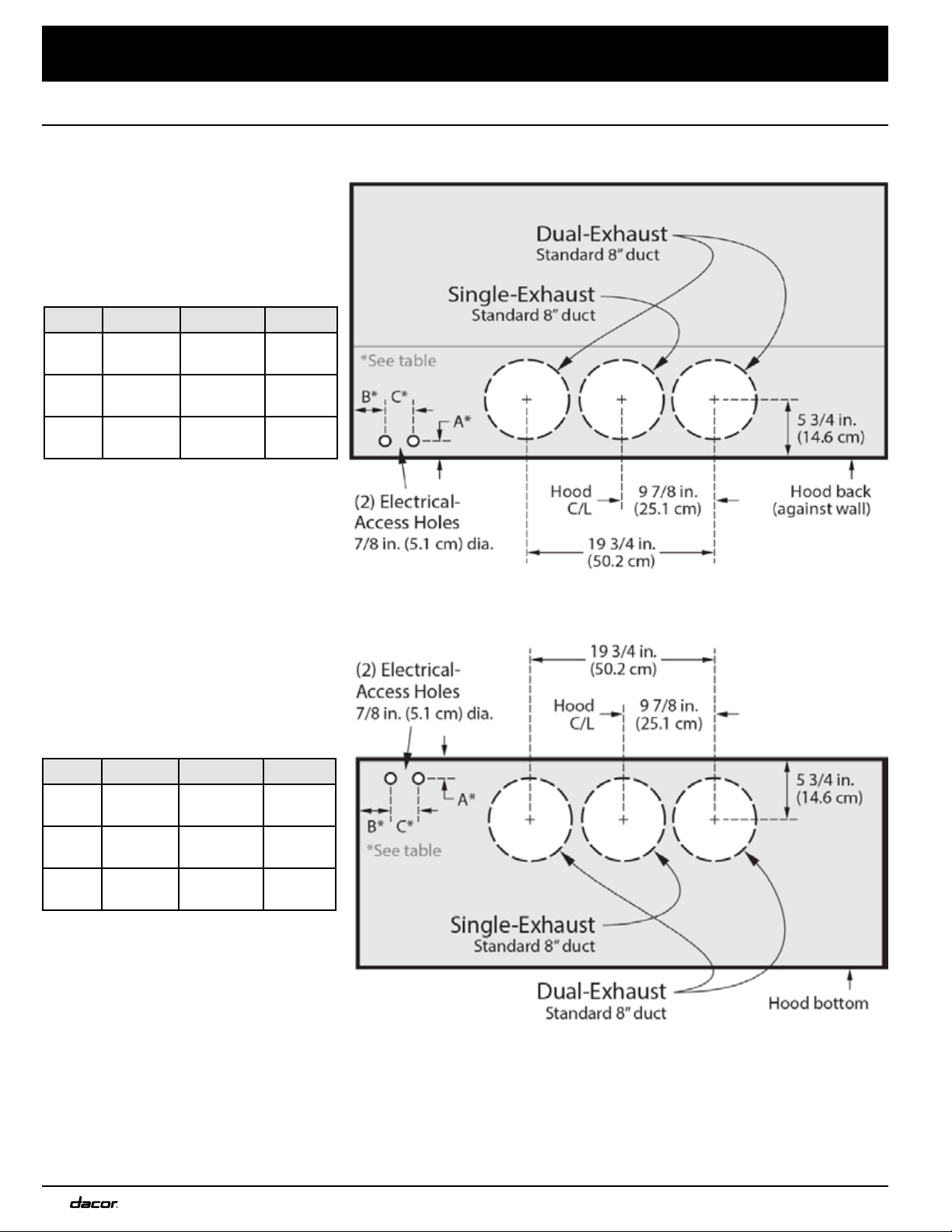
Dimensions (Electrical/Ductwork Connections)
Product Specifications
Connect electrical wires and ductwork through the top or rear of the hood. Before installing the hood, mark the access
holes according to the diagrams below. (Tolerances: +1/16” -0”, unless otherwise stated.)
Rear Connections: All Models
Model A B C
48 1 1/2 in.
(3.81 cm)
5 in.
(12.7 cm)
3 in.
(7.62 cm)
36 1 1/2 in.
(3.81 cm)
4 1/2 in.
(11.43 cm)
3 in.
(7.62 cm)
30 1 1/2 in.
(3.81 cm)
5 1/2 in.
(13.97 cm)
3”
(7.62 cm)
Dimensions: Top Electrical
Access Holes (RNHP, RNHE)
Top Connections: All Models
Dimensions: Rear Electrical
Access Holes (RNHP, RNHE)
5
Model A B C D
3012 29 7/8” (75.9 cm)
25 1/2”
(63.8
cm)
12”
(30.48 cm)
11 7/8”
(30.2 cm)
3612 35 7/8” (91.1 cm)
4812 47 7/8” (121.6 cm)
3018 29 7/8” (75.9 cm)
25 1/2”
(63.8
cm)
18”
(45.7 cm)
11 7/8”
(30.2 cm)
3618 35 7/8” (91.1 cm)
4818 47 7/8” (121.6 cm)
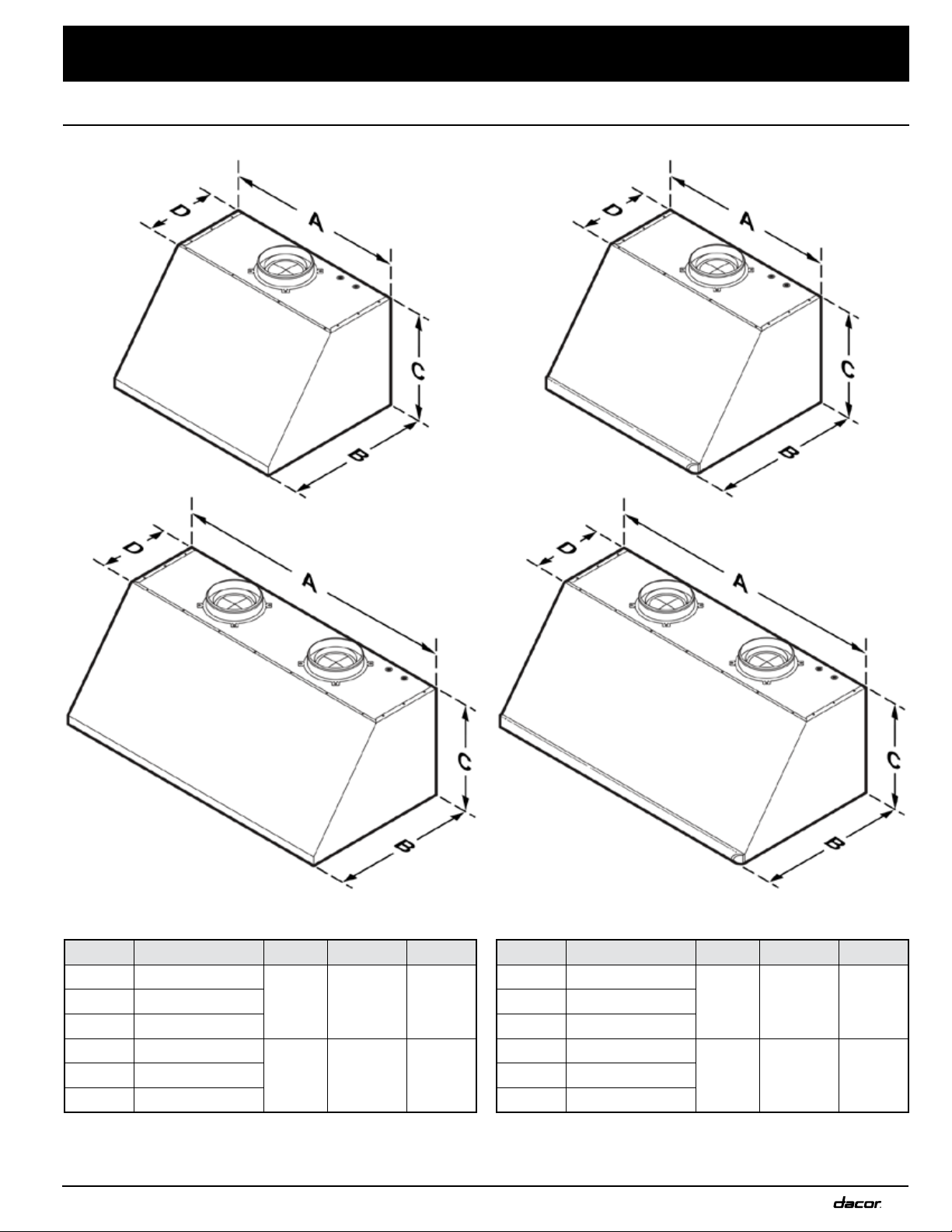
Product Specifications
Dimensions
Tolerances: +1/16” -0” unless otherwise stated.
Dual Blower:
RNHP48 Series
RNHP Hood Dimensions
Single Blower:
RNHP30/36 Series
Dual Blower:
RNHE48 Series
Single Blower:
RNHE30/36 Series
Model A B C D
3012 29 7/8” (75.9 cm)
24”
(61 cm)
12”
(30.48 cm)
11 7/8”
(30.2 cm)
3612 35 7/8” (91.1 cm)
4812 47 7/8” (121.6 cm)
3018 29 7/8” (75.9 cm)
24”
(61 cm)
18”
(45.7 cm)
11 7/8”
(30.2 cm)
3618 35 7/8” (91.1 cm)
4818 47 7/8” (121.6 cm)
RNHE Hood Dimensions
6
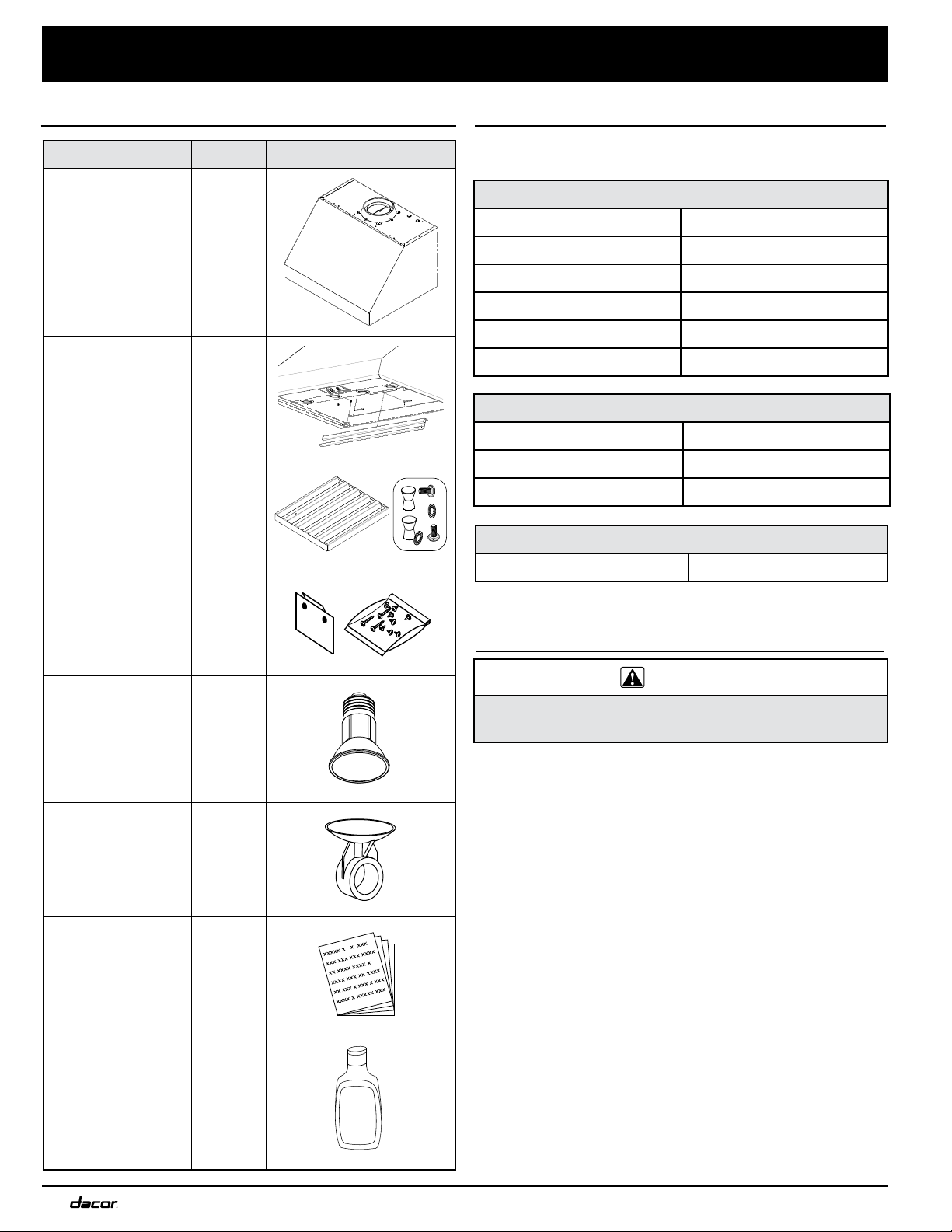
Part Qty Example
Hood (models
vary in size/
appearance)
1
Grease channel 1
Baffle-style filter
w/knobs (ready-
to-assemble kit)
48” (4)
36” (3)
30” (2)
Holding brackets,
hardware
2
Dimmable LED
light bulbs
48” (4)
36” (3)
30” (2)
Light-
replacement tool
1
Product literature
(Installation, Use-
and-Care guides)
2
Dacor cleaning
cream
1
STAINLESS
STEEL
CLEANER
Preparation and Setup
Parts List
Have these tools and hardware within reach before you
start the installation.
Blower Rotation (option)
Phillips screwdriver 5/16” Nut driver
Dual-to-Single Vent Transition Kit (option)
Dacor Kit #AHT10 Sheet-metal screws
10” Ducts, ducting material Foil tape
Drill, bits
Needed Tools/Hardware
Hood Installation
Phillips screwdriver Level
Flathead screwdriver Junction box
Pencil/marking tool Jigsaw
Wire connector caps 8” Ducting
Wire stripper Foil tape
Drill, bits Sheet-metal screws
WARNING
Make sure a licensed electrician installs the electrical
service to the range hood.
• The owner is responsible for verifying that all electrical
requirements are met by the qualified electrician servicing
this appliance.
• The electrical installation (incl. the minimum supply-
wire size and grounding) must comply with the National
Electric code ANSI/NFPA (or latest revision), local
codes, and ordinances. Obtain a copy of the ANSI/NFPA
standard from:
National Fire Protection Association
1 Batterymarch Park
Quincy, Massachusetts 02269-9101
• The ground terminal on the hood must be connected
to a grounded, metallic, permanent wiring system, or a
grounding conductor installed by a licensed electrician.
• Do not ground the appliance or appliance wiring to a gas
pipeline or to the neutral (white) power supply wire.
• Do not install a fuse in the neutral or ground circuit.
• Connect the hood directly to an electrical junction
box. Hard-wire the hood according to local code directly
to a dedicated three-wire grounded, single phase circuit
rated at 120 Vac 60 Hz, 15 Amp.
Meeting Electrical Codes
 Loading...