

Page 1
CybTouch 6 G
for Adjustable Rake Angle Shears
Technical Manual
Page 2
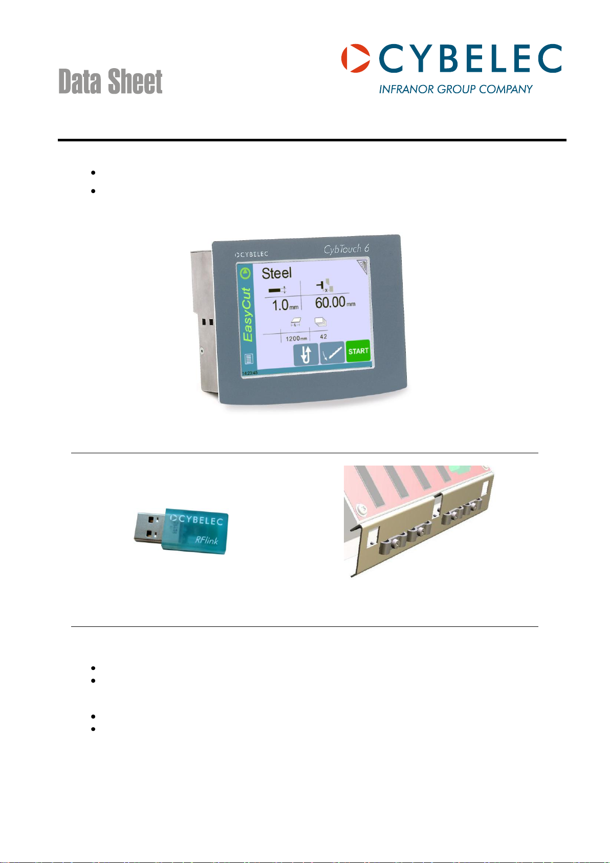
The CybTouch 6 for shears is specifically intended for sheet metal cutting. Two versions are available:
Numerical Control CybTouch 6 W or G for Shears
Option: Earthing kit to easily mount and earth the
cable shields.
Option: Wireless RFlink USB key for PC.
The CybTouch 6 G for adjustable rake angle shears (16 inputs / 12 outputs).
The CybTouch 6 W for swing shears (8 inputs / 8 outputs).
Options
Ordering information
Product: Reference number:
CybTouch 6 W
Without earthing kit S-CT6-1A0808WNN
With earthing kit S-CT6-1A0808WNA
CybTouch 6 G
Without earthing kit S-CT6-1B1612GNN
With earthing kit S-CT6-1B1612GNA
Earthing kit (option), see above S-CT6-OPT_A
RFlink USB key for PC (option), with CybTouchTools software S-OPT-RFLINK
CDS_CybTouch6_G_W_v1.2.doc 1/5
Page 3

FOR OEM
FOR END USER
Inputs/outputs for direct operation of valves
for blade movements, blade gap, cutting
angle, cutting length and system pressure
without passing through relays.
Internal timers for smooth valve
commutation.
Reduced electrical wiring, electrical cabinet
size and equipment for lower start-up costs
on each shear.
Flexible software for configuration of axes,
inputs-outputs and auxiliary functions
according to specific needs.
Screen content can be simplified to its
minimum by removing all unnecessary
functions, buttons or information.
Quick set-up thanks to wizards for adjusting
axes, gains, speeds, rake angle, blade gap
and indexes.
New indexing functions reduce the quantity
of switches and wiring, while providing
more reliable indexing.
CybTouch 6 accepts encoders with or
without complementary signals.
RFlink, a wireless radio frequency
transmission integrated in the CybTouch,
allows easy parameters backups or
firmware upgrades. This provides modern,
fast and simple communication, with no
need to open the housing, no need of
connecting cable *.
Very intuitive, no explanations required.
Operator immediately feels confident and
comfortable using this control.
Immediate easy use of the shear for any new
user thanks to EasyCut page.
Energy saving thanks to integrated Eco mode
function that automatically stops the main
pump after x minutes of inactivity.
Full touch screen human machine interface
offers the best of modern technology.
Colors are vivid but not aggressive, providing
excellent readability thanks to the large
characters and big buttons.
Recurrent programs for producing complex
parts can be created and memorized for easy
reuse.
Pop-up messages for security or external
malfunctions.
RFlink wireless radio frequency data
communication allows backup and restoring
operations without any cable connection to the
numerical control *.
Many languages available directly in the
CybTouch 6.
Internal backup located in a special safe
memory allows the user to restore at any time
the original parameters; machine is running
again in an extremely short time in the event
of a memory loss or involuntary parameter
modification.
Advantages:
CDS_CybTouch6_G_W_v1.2.doc 2/5
* Need RFlink USB key (option)
Page 4

Back gauge axis
DC brushless or frequency converter.
Auto-tuning of the axis.
Configurable retraction of the back gauge during the cutting process.
Indexing in several modes.
Inch / mm.
Shear features
Adjustable rake angle shear
Swing shear
16 inputs / 12 outputs.
8 inputs / 8 outputs.
Automatic management of:
Blade gap,
Cutting angle and cutting length.
Automatic management of:
Blade gap OR cutting angle.
System pressure management with ramp for
pressure proportional valve.
NA
Angle management.
NA
Cutting length management by:
Potentiometer, or
Encoder. See table below*.
Cutting length management by:
Timer.
Blade gap with:
1, or
2 actuators.
Blade gap with:
1 actuator (motor).
Foldaway:
Mechanical, or
Hydraulic.
Foldaway:
Mechanical.
Linearization of the blade gap curve for optimal positioning accuracy.
EasyCut page at start up for easy use.
Management of delays between the pressure valve (ON-OFF) and the direction valves.
Up to 10 pre-programmable types of materials.
Backgauge clearance during the cutting process (yes / no).
Sequence repetition.
AutoCut (Flying Cut or continuous cut) function.
Screen button and outputs for sheet support with 2 or 3 positions.
RTS (Return to sender) function.
Screen button for cutting laser / light guide.
Part counter with auto-stop.
Time and stroke counters for oil service.
Sheet offset (multiple-cuts in the middle of the machine with reduced TDC).
Eco mode.
Pump start button.
Axis and Shear Features
The below elements are available and can be configured on CybTouch by the OEM. However, some
functions of course depend on the machine construction.
Available features depend on the number of available axes and inputs/outputs.
CDS_CybTouch6_G_W_v1.2.doc 3/5
Page 5
Only possible potentiometer and encoder combinations
Adjustable rake angle shear
Swing shear
1 blade gap
= potentiometer.
Cutting length&angle
= potentiometer.
Back gauge
= encoder.
1 blade gap
= potentiometer.
Cutting length&angle
= encoder.
Back gauge
= encoder.
2 blade gap
= 2 potentiometers.
Cutting length&angle
= encoder.
Back gauge
= encoder.
1 blade gap
= potentiometer.
Back gauge
= encoder.
Characteristic
Adjustable rake angle shear
Swing shear
Screen
5.7" color graphic CRT screen 640 x 480 pixels with LED backlight control.
Work memory
SRAM.
System memory
FLASH memory with firmware update via RFlink.
Communication
Cybelec RFlink (radio frequency link).
Axis
+/- 10VDC management of AC/DC drives and motors, or
0-10 VDC frequency converter for AC asynchronous motors.
Units
Conversion Inch/mm.
Power supplies
NC: stabilized + 24VDC -15% / + 20% 15W.
digital inputs/outputs: stabilized + 24VDC -15% / + 20% (24V-I/O).
Encoder inputs
5 VDC or 12 VDC* or 24 VDC* (* = external power supply).
Complementary signals are not necessary, but recommended.
Power supplies
for encoders
5 VDC (supplied by CybTouch) max. 250 mA for each encoder.
Optocoupled
Digital inputs
16 inputs.
8 inputs.
Analog inputs
2 analog inputs 0-10 VDC.
Short circuit proof.
1 analog input 0-10 VDC.
Short circuit proof.
Digital outputs
12 outputs.
Optocoupled short circuit proof.
24 VDC source mode, max. 3A
Possibility to define 2 outputs for
doubling the current.
8 outputs.
Optocoupled short circuit proof.
24 VDC source mode, max. 3 A
Possibility to define 2 outputs for
doubling the current.
Analog outputs
4 analog outputs -/+10 VDC,
impedance out < 100 ,
load 2 k (max 15 mA).
Short circuit proof.
1 analog outputs -/+10 VDC,
impedance out < 100 ,
load 2 k (max 15 mA).
Short circuit proof.
Reference
voltage
One of the above analog outputs is used
for the 10VDC reference.
1 reference voltage 10 VDC
(max 20 mA) for external pot.
Recommended attached
potentiometer value (2k to 5k).
Operating
conditions
Min. 5° Celsius, max. 40° Celsius.
Relative humidity 10 to 85% noncondensing.
Dimensions
See diagram next page.
EC Directives
IEC61131-2 type 1-3 compliant.
Technical Characteristics
CDS_CybTouch6_G_W_v1.2.doc 4/5
Page 6
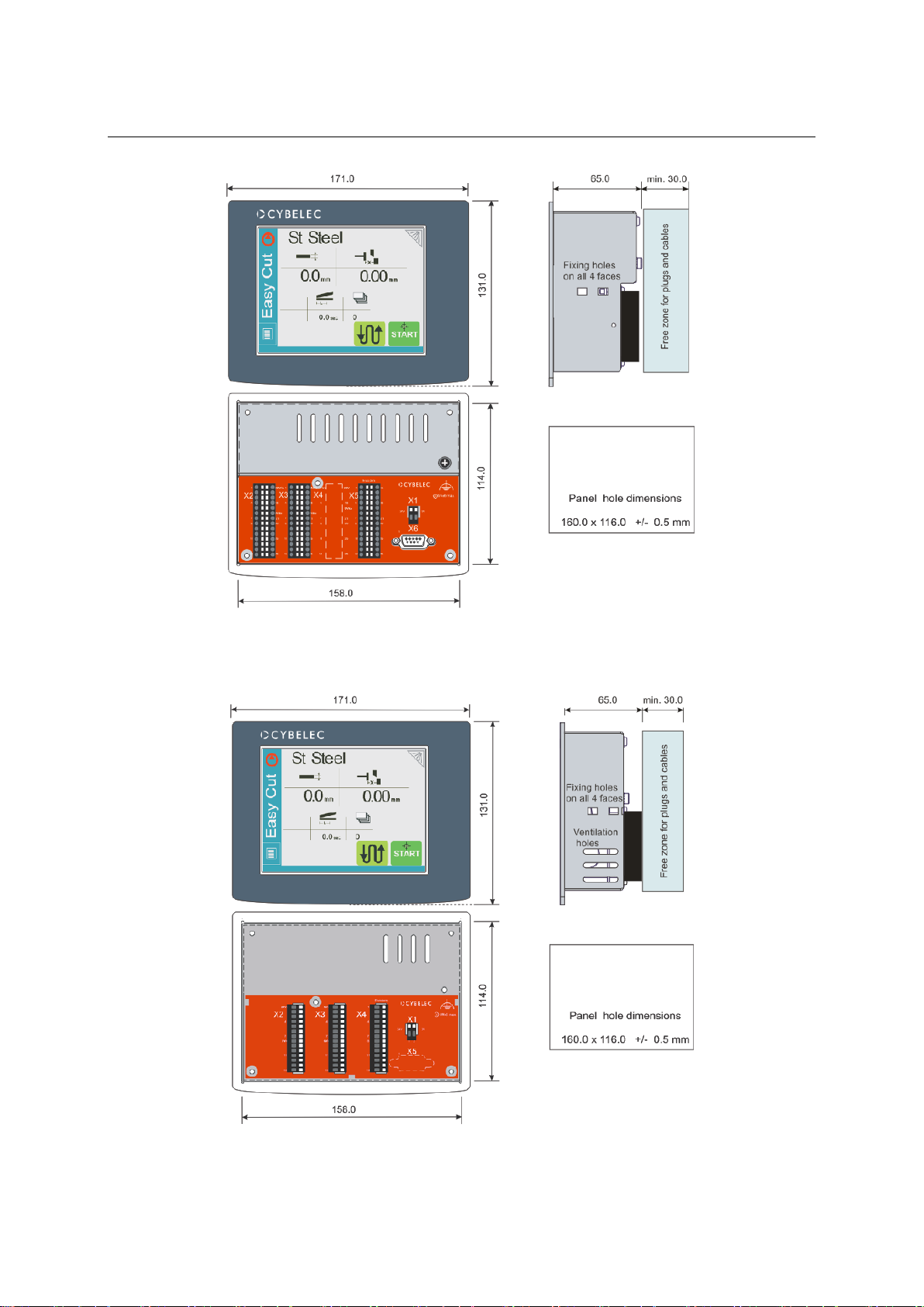
Dimensions
CybTouch 6 G for adjustable rake angle shear, 1 axis, 16 inputs, 12 outputs:
CybTouch 6 W for swing shear, 1 axis, 8 inputs, 8 outputs:
CDS_CybTouch6_G_W_v1.2.doc 5/5
Page 7
Rue des Uttins 27 CH-1401 Yverdon Switzerland TEL:+ 41 24 447 02 00 FAX:+ 41 24 447 02 01 E-Mail: info@cybelec.ch
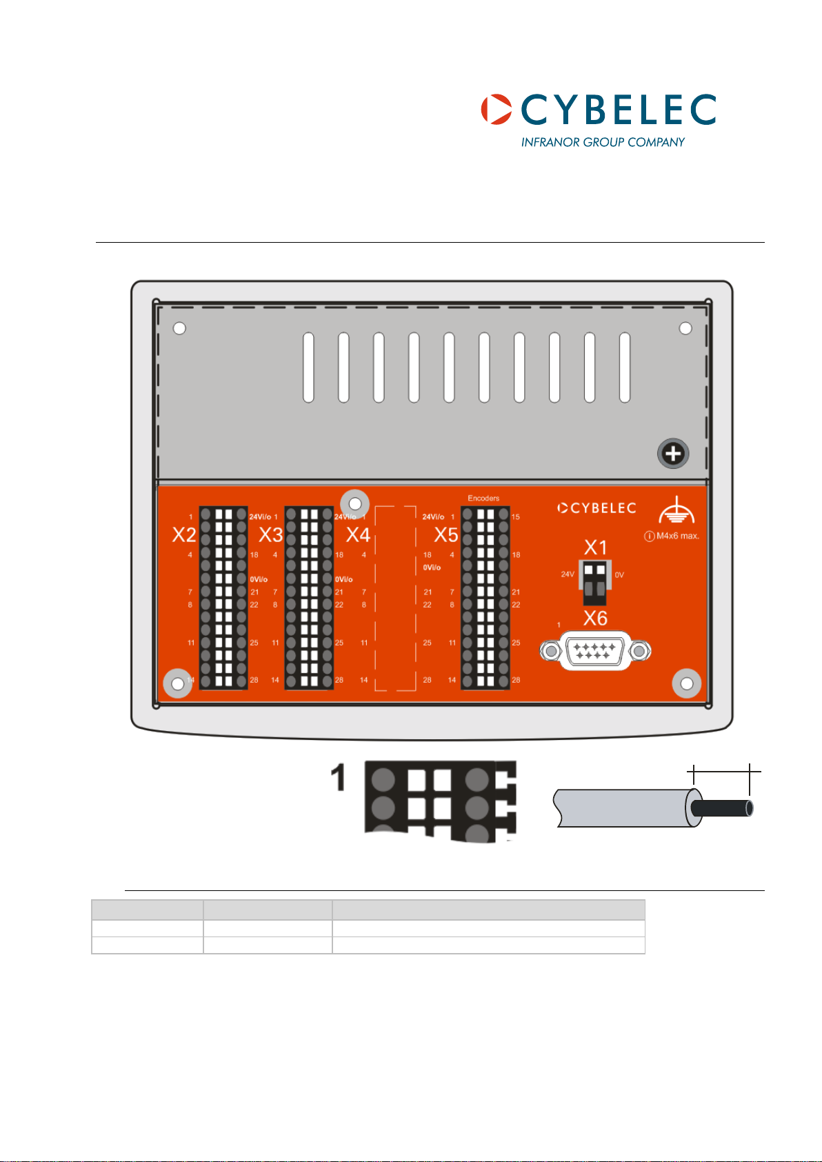
Connectors X2 to X5 =
Weidmüller B2L 3.5/28/180 SN BK
Max 4 A / connector pin.
max 8 mm0.75 mm
2
X1
Signal
Default I/0
1
24 V
24 VDC DNC
2
0V
0V DNC
Input/Output List for CybTouch 6 G (16/12 i/o)
Angle / cutting length with encoder
X1 Power Connector
CybTouch6_G_1612io_v1.1b.doc Page 1 of 7
Page 8
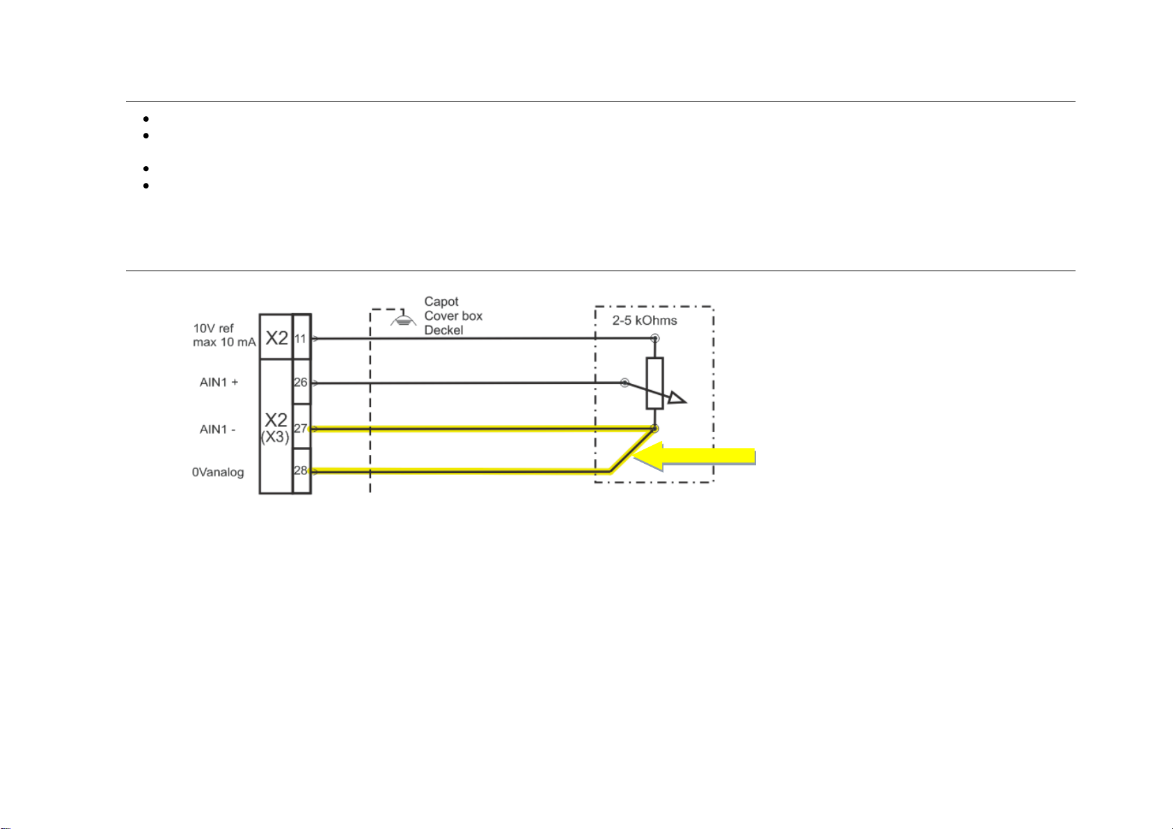
A 4 wires shielded cable must
be used for the potentiometer.
X2/27and X2/28 terminals
must be connected together
at one side of the potentiometer.
Generalities
All 0V_I/O pins are connected together.
All digital outputs are capable of driving a load (for example valves) up to 3 A maximum.
Digital outputs are short-circuit and overload protected.
Inductive loads must be equipped with surge suppressors.
The 24V_I/O pins from connectors X2 and X5 are connected together.
The symbols mentioned in this list (,,) are only a sample of use.
See basic diagram also.
Blade Gap Wiring
CybTouch6_G_1612io_v1.1b.doc Page 2 of 7
Page 9

X2
Signal
Default I/0
X2
Signal
Default I/0
1
24V_I/O
24 VDC electrical box in
Max 4 A / connector pin.
15
24V_I/O
24 VDC electrical box in
Max 4 A / connector pin.
2
OUT 1
Enable X (or SP)
16
IN 1
Pedal down
3
OUT 2
Pump on / Eco mode off
17
IN 2
Automatic cut
4
0V_I/O
0 V electrical box out
18
IN 3
TDC max
5
OUT 3
System pressure
19
IN 4
6
OUT 4
Blade down
20
0V_I/O
0 V electrical box in
7
0V_I/O
0 V electrical box out
21
IN 5
X index zone
8
OUT 5
Blade up
22
IN 6
9
OUT 6
SN X axis
23
IN 7
10
0V_I/O
0 V electrical box out
24
IN 8
11
AOUT 1
Ref 10V out (max 20mA)
Blade gap potentiometer / 10V (2 kOhms pot)
25
0Vanalog
0V analog out
12
0Vanalog
26
AIN1 +
Blade gap potentiometer / cursor
13
AOUT 2
X analog out
27
AIN1 -
Blade gap potentiometer / 0V ,
14
0Vanalog
X 0V analog out
28
0Vanalog
Blade gap potentiometer / 0V -
Refer to electrical box wiring diagram
X3
Signal
Default I/0
X3
Signal
Default I/0
1
24V_I/O
24 VDC electrical box in
Max 4 A / connector pin.
15
24V_I/O
24 VDC electrical box in
Max 4 A / connector pin.
2
OUT 7
Blade gap + / Light
16
IN 9
3
OUT 8
Blade gap -
17
IN 10
4
0V_I/O
0 V electrical box out
18
IN 11
5
OUT 9
Cutting angle +
19
IN 12
6
OUT 10
Cutting angle -
20
0V_I/O
0 V electrical box in
7
0V_I/O
0 V electrical box out
21
IN 13
8
OUT 11
Blade gap 2 +
22
IN 14
9
OUT 12
Blade gap 2 -
23
IN 15
10
0V_I/O
0 V electrical box out
24
IN 16
11
AOUT 3
Proportional pressure valve (0-10VDC)
25
0Vanalog
12
0Vanalog
0 V Pressure valve
26
AIN2 +
Blade gap 2 potentiometer / cursor *
13
AOUT 4
27
AIN2 -
Blade gap 2 potentiometer / 0V
14
0Vanalog
28
0Vanalog
Blade gap potentiometer / 0V -
Refer to electrical box wiring diagram
The pin attributions are programmable. The list below is a default proposal.
X2 I/O Connector
X3 I/O Connector
* Crowning depends on the machine and can be set or not in machine parameters.
CybTouch6_G_1612io_v1.1b.doc Page 3 of 7
Page 10

X5
Signal
Default I/0
X5
Signal
Default I/0
1
5V encodeur
5V out for encoder X
15
Z1+
Index encoder X
2
0V encodeur
0V out for encoder X
16
Z1 -
Index - encoder X
3
A1+
A signal of encoder X
17
B1+
B signal of encoder X
4
A1 -
A - signal of encoder X
18
B1 -
B - signal of encoder X
5
0V encodeur
19
0V encodeur
6
5V encodeur
5V out for angle / length encoder
20
Z2+
Index angle / length encoder
7
0V encodeur
0V out for angle / length encoder
21
Z2 -
Index - angle / length encoder
8
A2+
A signal of angle / length encoder
22
B2+
B signal of angle / length encoder
9
A2 -
A - signal of angle / length encoder
23
B2 -
B - signal of angle / length encoder
10
0V encodeur
24
0V encodeur
11
5V encodeur
25
Z3+
12
0V encodeur
26
Z3 -
13
A3+
27
B3+
14
A3 -
28
B3 -
Z+ Z-
X5 Encoder Connector
Use twisted pair cables for encoder signals.
Do not invert index signals (normal and inverted, Z+ and Z-).
It will result in a bad indexation procedure (lost of precision) difficult to trace or no indexation at all. If this
happens try to invert index signals.
Use twisted pair cables for encoder signals.
Encoder inputs support 12VDC and 24VDC signals. In this case encoder must be powered externally with its own power supply.
0V encoder must be common. See page 7 of this document for more details.
Encoder inputs support encoders without inverted signals.
CybTouch6_G_1612io_v1.1b.doc Page 4 of 7
Page 11

12 / 24 V Single Ended (Unipolar) Encoders
Encoder inputs support 12VDC and 24VDC signals. In this case encoder must be powered externally with its
own power supply. 0V encoder must be common.
Encoder inputs support encoders without inverted signals.
Emitter follower encoder outputs must be connected to
the negative (A+ B+) inputs on the CybTouch.
Any unused inputs must be left disconnected.
5V single ended encoders may take their 5V power
supply from the CybTouch.
Open collector encoder outputs must be connected to
the positive (A- B-) inputs on the CybTouch
Any unused inputs must be left disconnected.
5V single ended encoders may take their 5V power
supply from the CybTouch.
Push-pull encoder outputs must be connected to the
positive (A+ B+) inputs on the CybTouch.
Any unused inputs must be left disconnected.
5V single ended encoders may take their 5V power
supply from the CybTouch.
5 V Differential Encoders / Emulated Encoders
Differential encoders (TTL / 422 / 485) are usually 5V
powered. All channels must be connected.
Usually, the 5V of emulated encoders (servodrives) output must NOT be connected to the 5V
encoder of the CybTouch.
This may be dangerous for the drive or the CybTouch.
But some drives are fully opto-coupled and 5V encoder
must be provided like for a normal encoder.
Please refer to the drive datasheet.
External Encoder
When wiring an
external encoder, it is
important that the power
supplies be connected
as explained here.
CybTouch6_G_1612io_v1.1b.doc Page 5 of 7
Page 12

4 mm²
0V and ground connection
X2
24Vio
0Vio
4
7
0Vio
11
14
X3 X4
4
7
0Vio
11
14
Encoders
1
4
7
8
11
14
X1
24V
12
X5
1
M4x6 max.
i
0V
4 mm²
0 V
Power
230 V
supply
24V NC
24V I/O
24 V
Page 13

Configuration with:
- angle / cutting length with potentiometer feedback
- 1 blade gap actuator with potentiometer feedback
- on-off pressure valve system (or not)
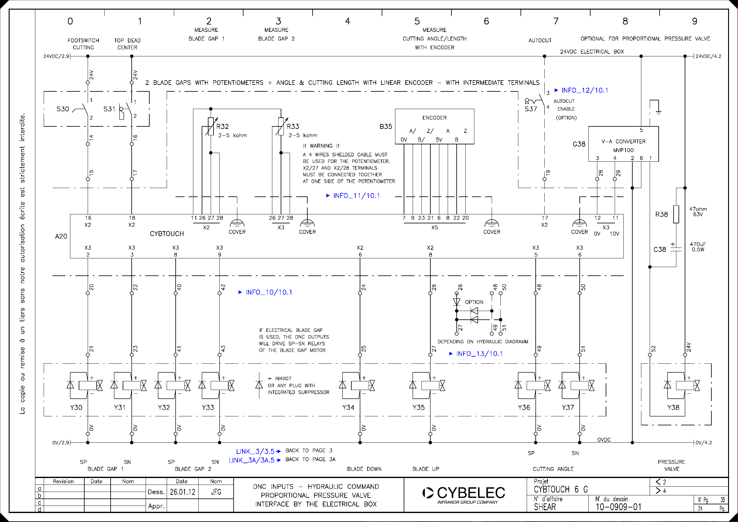
Configuration with:
- angle / cutting length with encoder feedback
- 2 blade gap actuators with potentiometer feedback
- proportional pressure valve
P01.01 Machine type = Adj.rake angle
P01.07 Second blade gap = yes
P03.10 Cutting length sensor = potentiometer
P03.10 Cutting length sensor = encoder
Default Configuration for Adjustable Rake Angle Shears
CybTouch6_G_1612io_v1.1b.doc Page 6 of 7
Page 14

CybTouch6_G_1612io_v1.1b.doc Page 7 of 7
Page 15

0 1 2 3 4 5 6 7 8 9
S10
12345
Q12
6
642
K27
531
12345
12345
K26
6
6
K25
12345
K28
6
F15
1
65432
1
EMO RELAY
65432
L11/4.0
L21/4.0
L31/4.0
G17
1
F17
L1 L2 L3 PE
0V 24V
65432
L1XL2
L3
PE
M12
U
X
UZVXWYPE
M
3~
V
W
PE
YZX
La copie ou remise à un tiers sans notre autorisation écrite est strictement interdite.
MAIN POWER SUPPLY
WITH EXTERNAL FUSES POWER SUPPLY
3x400V - 50/60Hz
Revision Date
a
b
c
d
Dess.
Appr.
26.01.12
PUMP MOTOR
NomDate Nom
JFG
MAIN POWER SUPPLY - PUMP MOTOR
POWER SUPPLY SERVO DRIVES
POWER SUPPLY 24VDC FOR COMMAND
SERVO DRIVES
24VDC
0VDC
24VDC POWER SUPPLY MUST BE FILTERED AND REGULATED
RELAYS AND VALVES MUST BE EQUIPPED WITH SUPPRESSORS
POWER SUPPLY
24VDC FOR COMMAND
24V
0V/2.0
Projet
CYBTOUCH 6 G
N° d'affaire N° du dessin
SHEAR
10-0909-01
<
>
2
N° Pg.
24
1
Pg.
Page 16

0 1 2 3 4 5 6 7 8 9
24VDC
24V
24VDC ELECTRICAL BOX
24VDC/3.0
0V/1.7
U20
0VDC 0VDC
13
F20
1
1A
2
K28
14
EMERGENCY
RELAY
13
K27
L N
SCHAFFNER FILTER
FN332-1/05
OR SIMILAR
L' N'
K25
K27
14
14
13
55
56
INFO_2/10.1
0V/3.0
6mm2
COVER
PE
CYBTOUCH
DIRECTLY CONNECTED TO THE FILTER
1 2 1 15 1 15 20
A20
/3.0
La copie ou remise à un tiers sans notre autorisation écrite est strictement interdite.
TO USE A FILTER IN THE DNC POWER LINE
X1 X1
IT'S HIGHLY RECOMMENDED
X2
24V
24V
X3
24V
24V
0V
X2
OUTPUT CURRENT
11
3
X2
PUMP ON
!! WARNING !!
MAX. 3A
K25
K26
22
21
A1
A2
21
/1.3
43
/1.3
65
/1.3
1413
.5
2221
.5
INFO_1/10.1
K26
K25
22
21
A1
A2
A1
K27
A2
21
/1.3
43
/1.3
65
/1.3
1413
2221
.5
21
43
65
1413
5655
H27
/1.2
/1.2
/1.2
.5
.5
X1
X2
S25
1
2
24V
K28
12
A1
A2
21
/1.5
43
/1.5
65
/1.5
1413
.2
POWER SUPPLY
24VDC DNC
Revision Date
a
b
c
d
Dess.
Appr.
26.01.12
NomDate Nom
JFG
POWER SUPPLY
24VDC I/O
POWER SUPPLY - DNC - I/O
PUMP START WITH CYBTOUCH START
BUTTON AND INTEGRATED ECO MODE
PUMP START WITH CYBTOUCH START BUTTON AND INTEGRATED ECO MODE
Projet
CYBTOUCH 6 G
N° d'affaire N° du dessin
SHEAR
EMERGENCY
PUSH-BUTTON
EMERGENCY
RELAY
10-0909-01
<
>
1
3
N° Pg.
24
2
Pg.
Page 17

24VDC/2.9
0 1 2 3 4 5 6 7 8 9
MEASURE MEASURE
FOOTSWITCH
CUTTING
TOP DEAD
CENTER
BLADE GAP
ANGLE/LENGTH
AUTOCUT
24VDC ELECTRICAL BOX
OPTIONAL FOR PROPORTIONAL PRESSURE VALVE
0VDC
24VDC/4.2
0V/4.20V/2.9
S30
A20
/2.0
/4.2
24V
1
S31
2
1
2
24V
1 BLADE GAP + ANGLE & CUTTING LENGTH WITH POTENTIOMETER
FOR ANGLE AND CUTTING LENGTH WITH ENCODER, SEE ON PAGE 3A
LINK/3A.4
S37
INFO_4/10.1
3
AUTOCUT
4
ENABLE
(OPTION)
R32 R33
1415
1617
2-5 kohm
2-5 kohm
!! WARNING !!
A 4 WIRES SHIELDED CABLE MUST
BE USED FOR THE POTENTIOMETER.
X2/27 AND X2/28 TERMINALS
MUST BE CONNECTED TOGETHER
AT ONE SIDE OF THE POTENTIOMETER
19
G38
V-A CONVERTER
3 4 1
28
INFO_3/10.1
16 18 11 26 27 28 26 27 28 17 12 11
X2X2
CYBTOUCH
X3 X2
X3 X3
2 4 3 7 6 7 8 10 5 10 6 20
X3
X2
COVER
COVER
X2 X2X2 X3 X3 X3X3X3
X2
COVER
X3
0V 10V
2 6
MVP100
29
5
47ohm
R38
C38
63V
470uF
0.5W
INFO_5/10.1
IF ELECTRICAL BLADE GAP
IS USED, THE DNC OUTPUTS
WILL DRIVE SP-SN RELAYS
OF THE BLADE GAP MOTOR
+
-
La copie ou remise à un tiers sans notre autorisation écrite est strictement interdite.
Y30
DNC CONNECTORS ARE EQUIPPED WITH OVDC TERMINALS TO MAKE THE WIRING OF EXTERNAL COMPONENTS MORE CONFORTABLE AND EASIER. REFER TO INPUT AND OUTPUT LIST FOR ADDITIONAL INFORMATION
Y31
+
-
= IN4007
OR ANY PLUG WITH
INTEGRATED SURPRESSOR
DIAGRAM WITH INTERMEDIATE TERMINALS IS SHOWN ON PAGE 3B
Y34
52
+
-
Y35
+
-
Y36
+
-
Y37
+
-
Y38
24V
+
-
LINK_3/3B.3
SP
BLADE GAP CUTTING ANGLE VALVE
Revision Date
a
b
c
d
SN
Dess.
Appr.
26.01.12
NomDate Nom
JFG
BLADE DOWN BLADE UP
DNC INPUTS - HYDRAULIC COMMAND
PROPORTIONAL PRESSURE VALVE
DIRECT CONNECTION TO DNC
SP SN
Projet
CYBTOUCH 6 G
N° d'affaire N° du dessin
SHEAR
10-0909-01
PRESSURE
2
<
4
>
N° Pg.
24
3
Pg.
Page 18

0 1 2 3 4 5 6 7 8 9
L11/1.6
L21/1.6
L31/1.6
U40
ENABLE
X AXIS
24VDC/3.9
0V/3.9
L1 L2 L3 PE
0VDC
ANALOG VOLTAGE
ENABLE
FREQUENCY CONVERTER (BASIC DIAGRAM)
U PEWV 0V
X AXIS
24VDC ELECTRICAL BOX
SN SP
X AXISX AXIS
SN SP10V
SERVO-AMPLIFIER SETTINGS
VOLTAGE INPUT (NO PRESET SPEED, NO PID, NO TORQUE INPUT)
ACCELERATION / DECELERATION RAMPS = NO
NO AUTOTEST (STATOR IMPEDANCE) AT ANY START
DNC SETTINGS
P09.01 SP-SN 0-10V OR EN/SN 0-10V
P09.02 CLOSED LOOP = NO / TIME BEFORE ? 0.5s
P11.02 INDEX ZONE REVERSE LOGIC = YES
31X32
32
PE
A20
/3.0
PEWVU
M40
La copie ou remise à un tiers sans notre autorisation écrite est strictement interdite.
M
3~
CYBTOUCH
X5
2 4 18 16 1 3 17 15
0V B/ 5V B
A/ Z/ A Z
34
35
21 2
COVER
36
X2
38
914 13
X2X2 X2 X2
S45
41
39
42
43
1
1
40
37
24V
1
S46
2
2
2
AC MOTOR
X AXIS
Revision Date
a
b
c
d
Dess.
Appr.
MESSAGE
X AXIS
26.01.12
NomDate Nom
JFG
ENCODER
X AXIS
SP - SN
X AXIS
X AXIS
FREQUENCY CONVERTER
BASIC DIAGRAM
X AXIS
INDEX ZONELIMIT SWITCH X AXISINDEX ZONE
SN - SP + SP +
Projet
CYBTOUCH 6 G
N° d'affaire N° du dessin
SHEAR
10-0909-01
<
>
3
8
N° Pg.
24
4
Pg.
Page 19
0 1 2 3 4 5 6 7 8 9
WIRING OPTIONS
La copie ou remise à un tiers sans notre autorisation écrite est strictement interdite.
Revision Date
a
b
c
d
Dess.
Appr.
26.01.12
NomDate Nom
JFG
Projet
CYBTOUCH 6 G
N° d'affaire N° du dessin
SHEAR
10-0909-01
<
>
4
N° Pg.
24
8
Pg.
Page 20

0 1 2 3 4 5 6 7 8 9
24V/1
0V/1.7
U20
24VDC
24VDC ELECTRICAL BOX
0VDC 0VDC
13
K28
1
1A
F20
2
L N
SCHAFFNER FILTER
FN332-1/05
OR SIMILAR
L' N'
EMERGENCY
RELAY
14
ECO MODE RELAY
A1
ECO
A2
21.522
ECO
START
21
22
3
4
56
K27
K25
14
13
13
14
INFO_6/10.1
24VDC/3.0
0V/3.0
PE
DIRECTLY CONNECTED TO THE FILTER
1 2 1 15 1 15 20 3
A20
La copie ou remise à un tiers sans notre autorisation écrite est strictement interdite.
TO USE A FILTER IN THE DNC POWER LINE
X1 X1
IT'S HIGHLY RECOMMENDED
X
6mm2
COVER
CYBTOUCH
X2
24V
24V
X3
24V
24V
0V
X2
11
X2
ECO MODE OFF
S25
1
2
24V
12
K25
K27
K26
55
21
22
A1
A2
21
K25
22
A1
K26
A2
21
/1.3
43
/1.3
65
/1.3
1413
.6
2221
.6
21
/1.3
43
/1.3
65
/1.3
1413
2221
.5
K27
A1
A2
X1
H27
21
/1.2
43
/1.2
65
/1.2
1413
.6
5655
.5
K28
X2
A1
A2
21
/1.5
43
/1.5
65
/1.5
1413
.2
POWER SUPPLY
24VDC DNC
Revision Date
a
b
c
d
Dess.
Appr.
26.01.12
NomDate Nom
JFG
POWER SUPPLY
24VDC I/O
POWER SUPPLY - DNC - I/O
PUMP START WITH CONVENTIONAL
START BUTTON AND ECO MODE
EMERGENCY
PUSH-BUTTON PUMP START WITH CONVENTIONAL START BUTTON AND ECO MODE
Projet
CYBTOUCH 6 G
N° d'affaire N° du dessin
SHEAR
10-0909-01
EMERGENCY
RELAY
1
<
3
>
N° Pg.
24
2A
Pg.
Page 21

0 1 2 3 4 5 6 7 8 9
24VDC
24V
24VDC ELECTRICAL BOX
24VDC/3.0
0V/1.7
U20
0VDC 0VDC
13
F20
1
1A
2
K28
EMERGENCY
RELAY
14
13
PUMP_ON
14
14
K27
L N
SCHAFFNER FILTER
FN332-1/05
OR SIMILAR
L' N'
PUMP ON RELAY
PUMP_ON
A1
A2
13 14
.5
K27
K25
56
55
13
13
14
INFO_7/10.1
0V/3.0
PE
DIRECTLY CONNECTED TO THE FILTER
1 2 1 15 1 15 20 3
A20
La copie ou remise à un tiers sans notre autorisation écrite est strictement interdite.
TO USE A FILTER IN THE DNC POWER LINE
X1 X1
IT'S HIGHLY RECOMMENDED
X
6mm2
COVER
CYBTOUCH
X2
24V
24V
X3
24V
24V
0V
X2
11
X2
PUMP ON
S25
1
2
24V
12
K25
K26
21
22
A1
A2
21
K25
22
A1
K26
A2
21
/1.3
43
/1.3
65
/1.3
1413
.6
2221
.6
21
/1.3
43
/1.3
65
/1.3
1413
2221
.5
K27
A1
A2
X1
H27
21
/1.2
43
/1.2
65
/1.2
1413
.6
5655
.5
K28
X2
A1
A2
21
/1.5
43
/1.5
65
/1.5
1413
.2
POWER SUPPLY
24VDC DNC
Revision Date
a
b
c
d
Dess.
Appr.
26.01.12
NomDate Nom
JFG
POWER SUPPLY EMERGENCY
24VDC I/O
PUSH-BUTTON
PUMP START WITH CYBTOUCH START
BUTTON AND INTEGRATED ECO MODE
BIG CONTACTOR (>3A) OR AC VOLTAGE
PUMP START WITH CYBTOUCH START BUTTON AND INTEGRATED ECO MODE
Projet
CYBTOUCH 6 G
N° d'affaire N° du dessin
SHEAR
10-0909-01
EMERGENCY
RELAY
1
<
3
>
N° Pg.
24
2B
Pg.
Page 22

24VDC/2.9
0 1 2 3 4 5 6 7 8 9
FOOTSWITCH
CUTTING
TOP DEAD
CENTER
MEASURE
BLADE GAP 1
BLADE GAP 2
CUTTING ANGLE/LENGTH
MEASUREMEASURE
WITH ENCODER
AUTOCUT
OPTIONAL FOR PROPORTIONAL PRESSURE VALVE
24VDC ELECTRICAL BOX
0VDC
24VDC/4.2
0V/4.20V/2.9
S30
A20
24V
1
S31
2
1415
1
2
24V
1617
2 BLADE GAPS WITH POTENTIOMETERS + ANGLE & CUTTING LENGHT WITH LINEAR ENCODER
LINK/3.5
R32 R33
2-5 kohm 2-5 kohm
!! WARNING !!
A 4 WIRES SHIELDED CABLE MUST
BE USED FOR THE POTENTIOMETER.
X2/27 AND X2/28 TERMINALS
MUST BE CONNECTED TOGETHER
AT ONE SIDE OF THE POTENTIOMETER
BACK TO PAGE 3
B35
ENCODER
A
0VA/B/Z/5V
S37
Z
B
INFO_8/10.1
16 18 26 17
X2X2
CYBTOUCH
X3 X3 X2
X3 X3
2 3 6 8 5
4 7 8 4 9 7 7 10 10 20
11 26 27 28 27 28 12 11
X2
X3 X3
X3 X3
COVER
X3
COVER
7 9 23 21 6 8 22 20
X5
X2 X2
X2
COVER
X2
X3 X3
X3 X3
INFO_9/10.1
3
AUTOCUT
4
ENABLE
(OPTION)
19
G38
COVER
6
2 6
V-A CONVERTER
MVP100
3 4 1
28
29
X3
0V 10V
5
R38
C38
47ohm
63V
470uF
0.5W
IF ELECTRICAL BLADE GAP
IS USED, THE DNC OUTPUTS
WILL DRIVE SP-SN RELAYS
OF THE BLADE GAP MOTOR
+
-
La copie ou remise à un tiers sans notre autorisation écrite est strictement interdite.
Y30
DNC CONNECTORS ARE EQUIPPED WITH OVDC TERMINALS TO MAKE THE WIRING OF EXTERNAL COMPONENTS MORE CONFORTABLE AND EASIER. REFER TO INPUT AND OUTPUT LIST FOR ADDITIONAL INFORMATION
Y31
+
-
Y32
+
-
Y33
+
-
DIAGRAM WITH INTERMEDIATE TERMINALS IS SHOWN ON PAGE 3B
= IN4007
OR ANY PLUG WITH
INTEGRATED SURPRESSOR
Y34
52
+
-
Y35
+
-
Y36
+
-
Y37
+
-
Y38
24V
+
-
LINK_3A/3B.3
SP SN
BLADE GAP 1
Revision Date
a
b
c
d
Dess.
Appr.
SP SN
BLADE GAP 2
NomDate Nom
26.01.12
JFG
BLADE DOWN BLADE UP
DNC INPUTS - HYDRAULIC COMMAND
PROPORTIONAL PRESSURE VALVE
DIRECT CONNECTION TO DNC
SP SN
CUTTING ANGLE
Projet
CYBTOUCH 6 G
N° d'affaire N° du dessin
SHEAR
10-0909-01
PRESSURE
VALVE
2
<
4
>
N° Pg.
24
3A
Pg.
Page 23
24VDC/2.9
S30
0 1 2 3 4 5 6 7 8 9
FOOTSWITCH
CUTTING
1
2
1415
TOP DEAD
S31
CENTER
MEASURE
BLADE GAP 1
24V
2 BLADE GAPS WITH POTENTIOMETERS + ANGLE & CUTTING LENGTH WITH LINEAR ENCODER - WITH INTERMEDIATE TERMINALS
1
2
R32 R33
1617
2-5 kohm 2-5 kohm
MEASURE
BLADE GAP 2
CUTTING ANGLE/LENGTH
B35
0VA/B/Z/5V
!! WARNING !!
A 4 WIRES SHIELDED CABLE MUST
BE USED FOR THE POTENTIOMETER.
X2/27 AND X2/28 TERMINALS
MUST BE CONNECTED TOGETHER
AT ONE SIDE OF THE POTENTIOMETER
INFO_11/10.1
MEASURE
WITH ENCODER
ENCODER
A
AUTOCUT
24VDC ELECTRICAL BOX
INFO_12/10.1
3
AUTOCUT
4
S37
Z
B
ENABLE
(OPTION)
19
OPTIONAL FOR PROPORTIONAL PRESSURE VALVE
5
G38
V-A CONVERTER
MVP100
2 63 4 1
28
29
24VDC/4.2
A20
16 18 26 17
X2X2
CYBTOUCH
X3 X3 X2
2 3 6 8 5
2021
+
-
2223
+
-
11 26 27 28 27 28
X2
X3 X3
8 9
4041
+
-
4243
+
-
COVER
INFO_10/10.1
X3
IF ELECTRICAL BLADE GAP
IS USED, THE DNC OUTPUTS
WILL DRIVE SP-SN RELAYS
OF THE BLADE GAP MOTOR
= IN4007
OR ANY PLUG WITH
INTEGRATED SURPRESSOR
COVER
7 9 23 21 6 8 22 20
X2
X3 X3
48
49
+
-
2425
X5
X2
2627
DEPENDING ON HYDRAULIC DIAGRAMM
2627
OPTION
COVER
49 48
51 50
INFO_13/10.1
+
-
+
-
COVER
6
+
-
12 11
0V 10V
50
51
X3
R38
C38
52
47ohm
63V
470uF
0.5W
24V
+
-
La copie ou remise à un tiers sans notre autorisation écrite est strictement interdite.
Y30
0V 24V
SP SN
BLADE GAP 1
Revision Date
a
b
c
d
Y31
0V
Y32
Dess.
Appr.
Y33
0V
SP SN
BLADE GAP 2
NomDate Nom
26.01.12
JFG
0V
LINK_3/3.5
LINK_3A/3A.5
DNC INPUTS - HYDRAULIC COMMAND
PROPORTIONAL PRESSURE VALVE
INTERFACE BY THE ELECTRICAL BOX
BACK TO PAGE 3
BACK TO PAGE 3A
Y34
0V
BLADE DOWN BLADE UP
Y35
0V
Y36
0V
SP SN
CUTTING ANGLE
Y37
0V
0VDC
Projet
CYBTOUCH 6 G
N° d'affaire N° du dessin
SHEAR
10-0909-01
Y38
PRESSURE
VALVE
2
<
4
>
0V/4.20V/2.9
N° Pg.
24
3B
Pg.
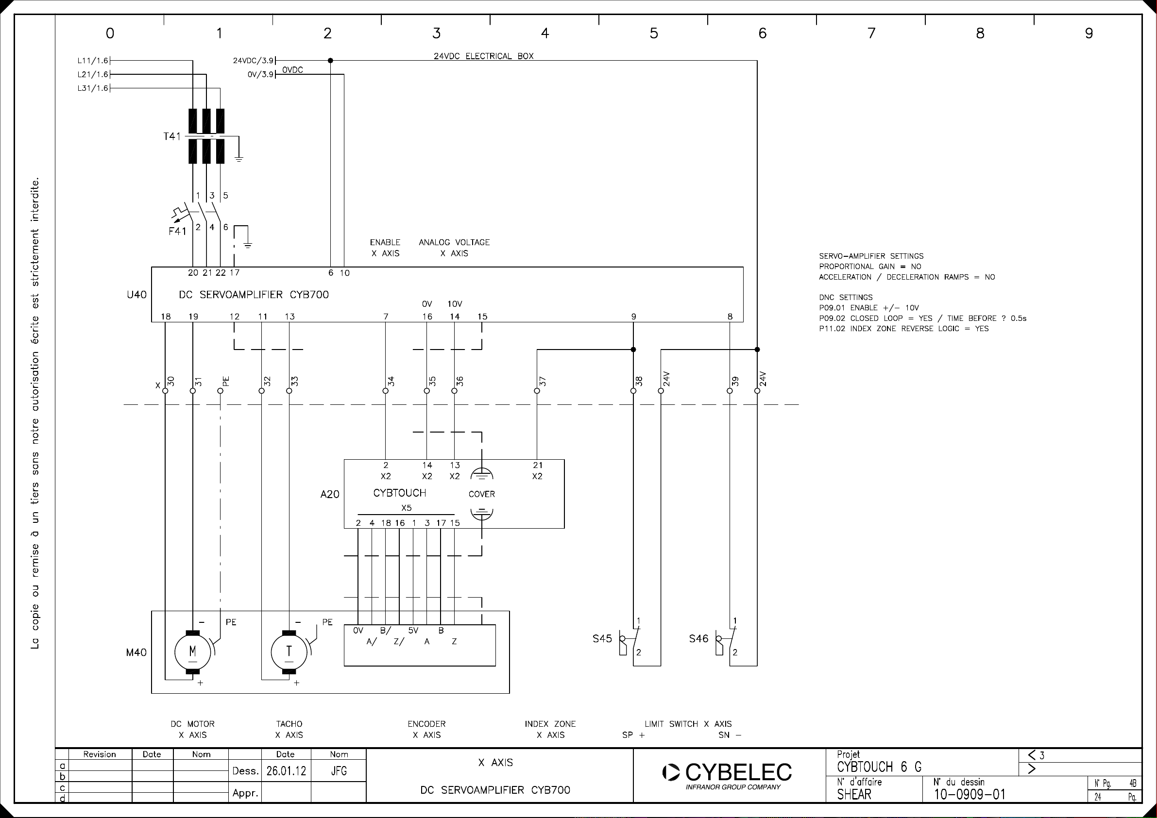
Page 24
0 1 2 3 4 5 6 7 8 9
L11/1.6
L21/1.6
L31/1.6
U40
24VDC/3.9
0V/3.9
0VDC
T41
3
1
654
2
F41
20 21 22 17
6
10
DC SERVOAMPLIFIER CYB700
18 11 1319 12 7
24VDC ELECTRICAL BOX
ANALOG VOLTAGEENABLE
X AXISX AXIS
0V 10V
16 14 15 9 8
SERVO-AMPLIFIER SETTINGS
PROPORTIONAL GAIN = NO
ACCELERATION / DECELERATION RAMPS = NO
DNC SETTINGS
P09.01 ENABLE +/- 10V
P09.02 CLOSED LOOP = YES / TIME BEFORE ? 0.5s
P11.02 INDEX ZONE REVERSE LOGIC = YES
30X31
-
La copie ou remise à un tiers sans notre autorisation écrite est strictement interdite.
M40
M
PE
PE
32
T
33
A20
2 4 18 16 1 3 17 15
PE
-
0V B/ 5V B
34
2 14 13
X2 X2 X2 X2
CYBTOUCH
X5
A/ Z/ A Z
35
36
COVER
21
37
S45
38
24V
1
1
39
24V
S46
2
2
+
Revision Date
a
b
c
d
Dess.
Appr.
+
TACHODC MOTOR
26.01.12
NomDate Nom
JFG
ENCODER
X AXISX AXISX AXIS
INDEX ZONE
X AXIS
X AXIS
DC SERVOAMPLIFIER CYB700
LIMIT SWITCH X AXIS
SP + SN -
Projet
CYBTOUCH 6 G
N° d'affaire N° du dessin
SHEAR
10-0909-01
<
>
3
N° Pg.
24
4B
Pg.
Page 25

0 1 2 3 4 5 6 7 8 9
L11/1.6
L21/1.6
L31/1.6
U40
24VDC ELECTRICAL BOX
SERVO-AMPLIFIER SETTINGS
PROPORTIONAL GAIN = NO
ACCELERATION / DECELERATION RAMPS = NO
DNC SETTINGS
P09.01 ENABLE +/- 10V
P09.02 CLOSED LOOP = YES / TIME BEFORE ? 0.5s
P11.02 INDEX ZONE REVERSE LOGIC = YES
T41
F41
24VDC/3.9
3
1
654
2
4 5 6 GND
X9
0V/3.9
0VDC
ONLY FOR 230V
SERVO-AMPLIFIER
23 24
1
X8 X2 X8
2
AC SERVOAMPLIFIER CD1-a
X9 X1
10 1 29 8 20
6 8 4 16 17GND 3 7 4 8 5 9 6
X2 X2
7 9 5 GND 15 1 14
ENABLE
X AXIS
ANALOG VOLTAGE
X AXIS
0V 10V
X2
X2 X2
30X32
La copie ou remise à un tiers sans notre autorisation écrite est strictement interdite.
M40
M
3~
X AXIS
31
PE
4 18 15 14 1316 3 17 2 21
A20
PEWVU
TC S3 S2 R1
TC S1 S4 R2
RESOLVERAC MOTOR
X AXIS
A/
33
X5 X2 X2
Z/
B/ A
B
COVER
Z
X2
COVER
CYBTOUCH
ENCODER
X AXIS
34
35
X2
X AXIS
36
S47
37
24V
1
1
S48
2
LIMIT SWITCH X AXISINDEX ZONE
SP + SN -
2
38
24V
Revision Date
a
b
c
d
Dess.
Appr.
26.01.12
NomDate Nom
JFG
X AXIS
AC SERVOAMPLIFIER CD1-a
Projet
CYBTOUCH 6 G
N° d'affaire N° du dessin
SHEAR
10-0909-01
<
>
3
N° Pg.
24
4A
Pg.
Page 26

0 1 2 3 4 5 6 7 8 9
INFO_1/2.5
INFO_2/2.6
INFO_3/3.4
INFO_8/3A.4
INFO_11/3B.4
INFO_4/3.7
INFO_9/3A.7
INFO_12/3B.7
INFO_5/3.1
This diagram can be used as long as the two contactors (star/delta) do not need more than 3A total.
If the star/delta set requires more than 3A (24VDC) or other voltage (AC for example) please use the diagram on page 2B
For other ways of starting the pump, please refer to the chapter "Wiring Options" at the end of this document
Important : A 4-wire shielded cable must be used for each of the potentiometers.
27 and 28 terminals must be connected together at one side of the potentiometer.
Refer to the wiring explanation in the inputs/outputs list. (bottom of X2 connector list)
AutoCut (=Flying cut) switch is optional
If OEM wants to secure the AutoCut function with an external key switch, the AutoCut input must be configured and wired
If only the AutoCut function (ON-OFF on screen) is needed, without an external keyswitch, then do not configure
the AutoCut input, only configure the AutoCut function.
In this wiring option, the connecting cables to the valves can be easily connected directly to the DNC.
The 0V_I/O terminals are available for this purpose on X2 and X3 connectors. (see inputs/outputs list)
This saves using terminals in the electrical box and makes the wiring simpler, easier and faster.
INFO_6/2A.7
INFO_7/2B.7
INFO_10/3B.2
INFO_13/3B.5
La copie ou remise à un tiers sans notre autorisation écrite est strictement interdite.
Conventional Start-Stop panel buttons.
This diagram shows the conventional pump start-stop buttons (usualy placed on the panel)
The Eco-mode relay is used to stop the main motor after x minutes of inactivity.
The EcoModeOff output is configured instead of the PumpOn output.
Whenever possible, we recommend that the Pump start button on the CybTouch and related PumpOn output be used.
This saves using the conventional start/stop buttons, is much more user friendly for the operator and integrates
the Eco-mode function.
This diagram is used if more than 3A is needed to activate the 2 simultaneous star/delta contactors.
It is also used when star/delta contactors are 24 VAC or 48 VAC.
This diagram is electrically the same as page 3A, but here the valves are
crossing through terminals instead of being directly connected to the numerical control.
If for rack angle adjustement a second valve must be activated, this can be done by diodes.
Limit is 3A per output. If needed, output may be doubled.
DateRevision NomDate Nom
a
b
c
d
Dess.
Applied Materials Confidential
26.01.12
JFG
NOTES ON DIAGRAMS
Projet
CYBTOUCH 6 G
N° d'affaire
SHEAR
N° du dessin
10-0909-01
<
>
N° Pg.
24
10
Pg.
 Loading...