

Page 1
TECHNICAL
DOCUMENTATION
Input/Output list
CybTouch 6 C (6/10io SBC-10A)
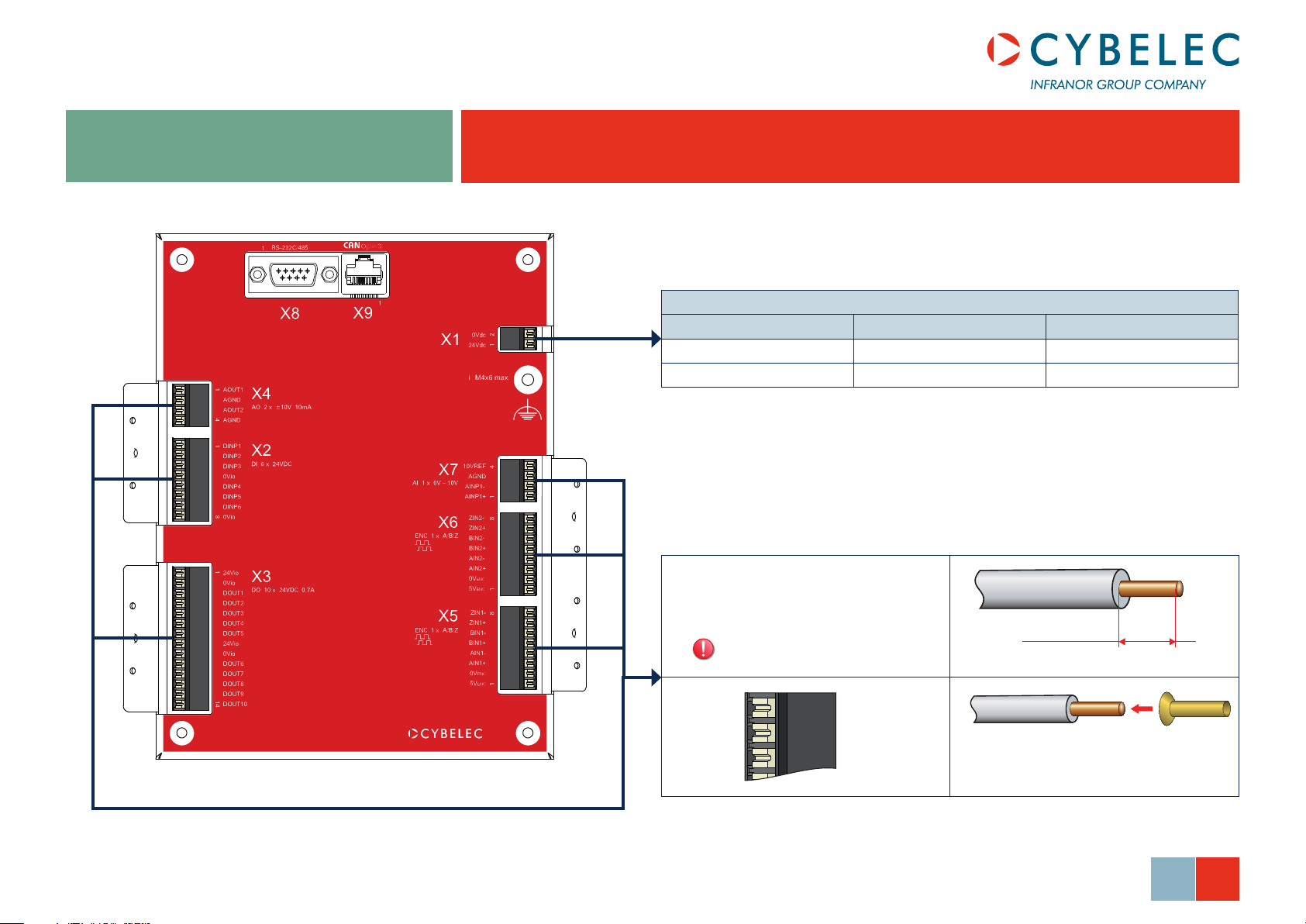
X1 Power Connector
X1 Signal Default I/0
1 24 V 24 VDC DNC
2 0 V 0 V DNC
Connectors X1 to X7
=
Weidmüller LSF-SMT 3.5/XX/135 SN BK
Max 4 A / connector pin.
Max. 8 mm
Section max = 1.5 mm
2
© Cybelec S.A. 2014
1 2 3
The encoder’s cables being of a very
small section (0.14 mm2), crimp an end
sleeve on their end.
Oct14
V2.1
1/7
Page 2
Input/Output list for CybTouch 6 C
Generalities
◊ All 0V_I/O pins are connected together.
◊ All digital outputs are capable of driving a load (for example valves) up to
0.7A typ. / 1A maximum.
◊ Digital outputs are short-circuit and overload protected.
◊ Inductive loads must be equipped with surge suppressors.
◊ See also basic diagram.
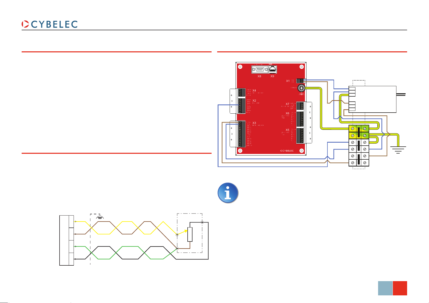
Analog Input Wiring
A 4 wires shielded cable must be used for the potentiometer.
X7/2 and X7/3 terminals must be connected together at one side of the
potentiometer.
The cable shield must be connected to the chassis of the CybTouch using the
grounding system.
If a twisted pair cable is used, use twisted pair shown.
Earth and 24 VDC Wiring
It is recommended that each supply connections (24V & 0V) is
individually connected to the power supply. It is not recommended to
connect them in series.
It is also recommended to separate the 24V I/O from the 24V NC.
24V NC
2
4 mm
24V I/O
0 V
24 V
230 V
Power
supply
AIN1+
AIN1 -
0V analog
10 V ref
max 10 mA
X7
1
2-5 kOhms
2
3
4
© Cybelec S.A. 2014
Oct14
V2.1
2/7
Page 3
Input/Output list for CybTouch 6 C
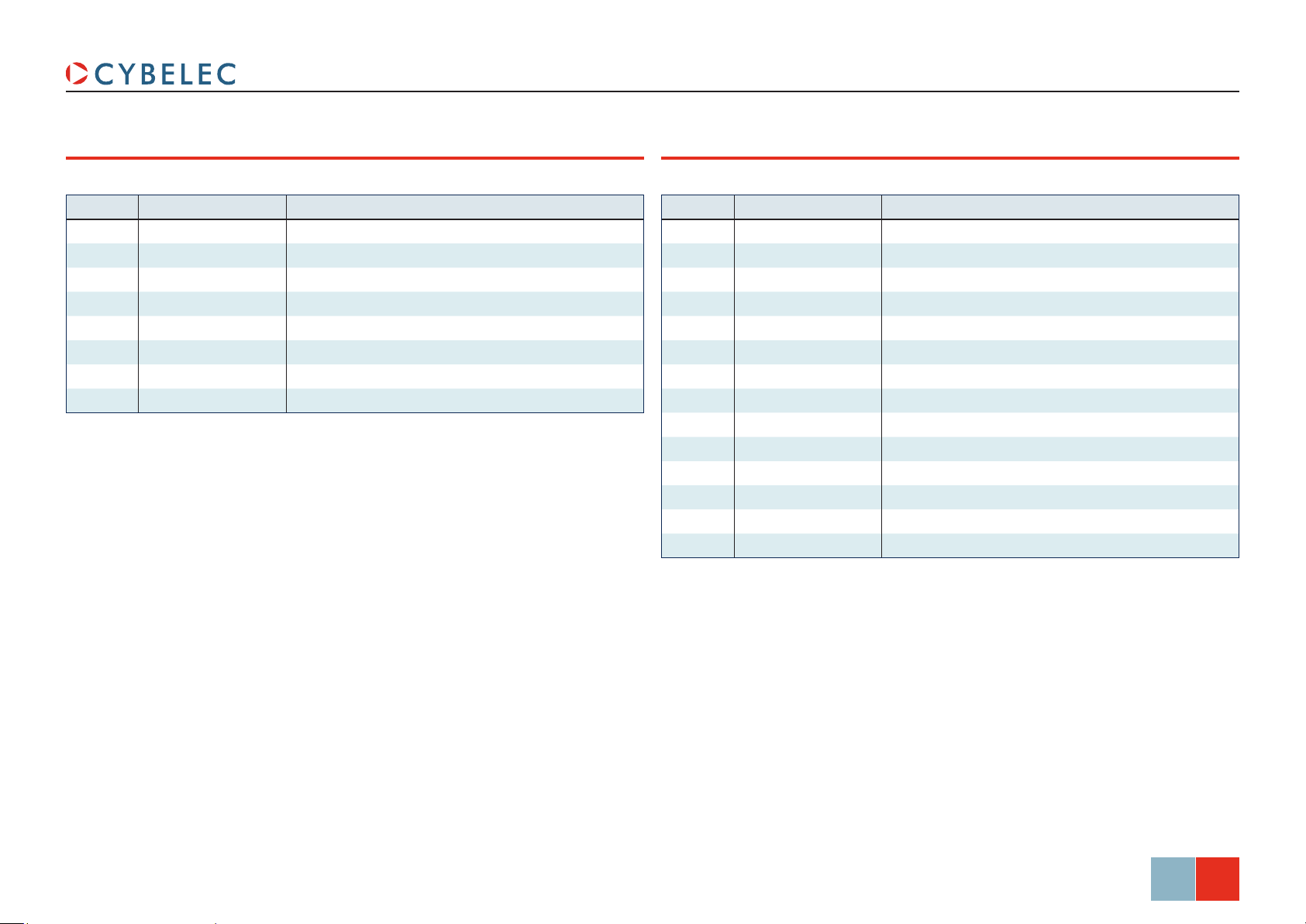
X2 Inputs Connector
X2 Signal Default I/0
1 IN 1 Downward command
2 IN 2 Upward command
3 IN 3 Comm. HS-LS beam
4 0V_I/O 0 V electrical box
5 IN 4 Start
6 IN 5 Stop
7 IN 6 X index zone
8 0V_I/O 0 V electrical box
X3 Outputs Connector
X3 Signal Default I/0
1 24V_I/O 24 VDC electrical box
2 0V_I/O 0 V electrical box
3 OUT 1 Pump on
4 OUT 2 Mach ready
5 OUT 3 Enable X axis
6 OUT 4 Aux funct £F1
7 OUT 5 Enable Y axis
8 24V_I/O 24 VDC electrical box
9 0V_I/O 0 V electrical box
10 OUT 6
11 OUT 7 Beam V1
12 OUT 8 Beam V2
13 OUT 9 Beam V3
14 OUT 10 TDC Seq
© Cybelec S.A. 2014
Oct14
V2.1
3/7
Page 4

Input/Output list for CybTouch 6 C
X4 Analog Outputs Connector
X4 Signal Default I/0
1 AOUT 1 Analog Out X
2 0Vanalog 0V analog
3 AOUT 2 Analog Out Y
4 0Vanalog 0V analog
X5 Encoder Connector
X5 Signal Assignation
1 5V encoder 5V out for encoder X
2 0V encoder 0V out for encoder X
3 A1+ A signal of encoder X
4 A1 - A - signal of encoder X
5 B1+ B signal of encoder X
6 B1 - B - signal of encoder X
7 Z1+ Index encoder X
8 Z1 - Index - encoder X
X6 Encoder Connector
X6 Signal Assignation
1 5V encoder 5V out for encoder Y
2 0V encoder 0V out for encoder Y
3 A2+ A signal of encoder Y
4 A2 - A - signal of encoder Y
5 B2+ B signal of encoder Y
6 B2 - B - signal of encoder Y
7 Z2+ Index encoder Y
8 Z2 - Index - encoder Y
Use twisted pair cables for encoder signals.
Encoder inputs support 12VDC and 24VDC signals. In this case
encoder must be powered externally with its own power supply. 0V
encoder must be common. See Encoder types (see page 6) for
more details.
Encoder inputs support encoders without inverted signals.
The encoder’s cables being of a very small section (0.14 mm
an end sleeve on their end.
Do not invert index signals (normal and inverted, Z+ and Z-).
It will result in a bad indexation procedure (loss of precision),
difficult to trace or no indexation at all. If this happens try to
invert index signals. Z+
and Z-
2
), crimp
© Cybelec S.A. 2014
Oct14
V2.1
4/7
Page 5

X7 Analog Inputs Connector
X7 Signal Default I/0
1 AIN1 +
2 AIN1 -
3 0Vanalog 0V analog
4 10Vref 10 VDC reference
See Analog Input Wiring (see page 2) for more details.
Input/Output list for CybTouch 6 C
© Cybelec S.A. 2014
Oct14
V2.1
5/7
Page 6

A+
24 VDC
+
-
Schaffner Filter
FN332-1/05
or similar
Encoder types
Input/Output list for CybTouch 6 C
12 / 24 V Single Ended (Unipolar) Encoders
Encoder inputs support 12VDC and 24VDC signals. In this case encoder must be
powered externally with its own power supply. 0V encoder must be common.
Encoder inputs support encoders without inverted signals.
Emitter follower
Emitter follower encoder outputs must
CybTouch
encoder inputs
A+
0V encoder
Open collector
CybTouch
encoder inputs
A-
0V encoder
Push pull
CybTouch
encoder inputs
A+
0V encoder
external
12/24V encoder
0V encoder
external
12/24V encoder
0V encoder
external
12/24V encoder
0V encoder
be connected to the A+ B+ inputs on
the CybTouch.
Any unused inputs must be left
disconnected.
5V single ended encoders may take
their 5V power supply from the
CybTouch.
Open collector encoder outputs
must be connected to the A – B –
inputs on the CybTouch
Any unused inputs must be left
disconnected.
5V single ended encoders may take
their 5V power supply from the
CybTouch.
Push-pull encoder outputs must be
connected to the A+ B+ inputs on the
CybTouch.
Any unused inputs must be left
disconnected.
5V single ended encoders may take
their 5V power supply from the
CybTouch.
5 V Differential Encoders / Emulated Encoders
Differential
CybTouch
encoder inputs
5V encoder
A+
A-
0V encoder
Differential encoders (TTL / 422 / 485)
are usually 5V powered. All channels
must be connected.
Emulated encoder on motor drives
The 5V of emulated encoders
(servo-drives) output must NOT
CybTouch
encoder inputs
5V encoder 5V
A+
A-
0V encoder
not connected
A+
A-
0V encoder
be connected to the 5V encoder
of the CybTouch.
This may be dangerous for the drive or
the CybTouch.
But some drives are fully opto-coupled
and 5V encoder must be provided like
for a normal encoder.
Please refer to the drive datasheet.
External Encoder
CybTouch
encoder inputs
0V encoder
CybTouch
power X1
0V
24V
When wiring an external encoder, it is important that the
power supplies be connected as explained here.
24V encoder
0V encoder
© Cybelec S.A. 2014
Oct14
V2.1
6/7
Page 7

Default Configuration
Input/Output list for CybTouch 6 C
© Cybelec S.A. 2014
Oct14
V2.1
7/7
 Loading...