

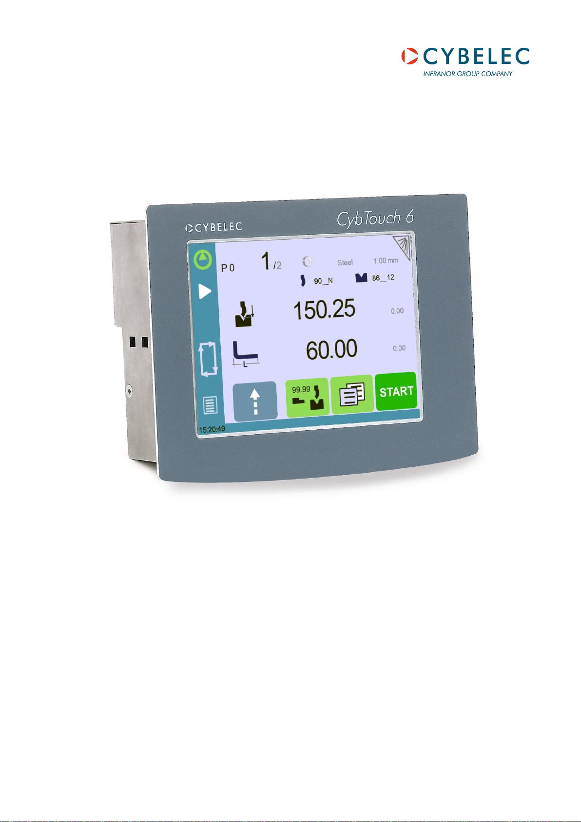
CybTouch 6 P
Press Brake
Machine Parameters Manual V.2.0

Page left blank intentionally

v2.0 Nov.12
TABLE OF CONTENTS
P01 MACHINE CONFIGURATION ......................................................................................................... 6
Menu Button ......................................................................................................................................... 6
Toggle Pages Button ........................................................................................................................... 6
P01.01 Machine Type .......................................................................................................................... 7
P01.02 Punch & Die Management ...................................................................................................... 7
P01.03 Start Pump Button ................................................................................................................... 7
P01.04 Quantity ................................................................................................................................... 8
P01.05 Material .................................................................................................................................... 8
P01.06 Retraction ................................................................................................................................ 8
P01.07 Bending Length ....................................................................................................................... 8
P01.08 TDC Return ............................................................................................................................. 8
P01.09 Bending Force ......................................................................................................................... 9
P01.10 Dwell Time ............................................................................................................................... 9
P01.11 Crowning ................................................................................................................................. 9
P01.12 X Axis ...................................................................................................................................... 9
P01.13 Y Axis ...................................................................................................................................... 9
P02 MACHINE CONFIGURATION 2 .................................................................................................... 10
P02.01 Auxilary Function ................................................................................................................... 10
P02.02 Eco Mode .............................................................................................................................. 10
P02.03 Store/Delete Programs in Level 0 ......................................................................................... 10
P02.04 Level 0 Lock HMI ................................................................................................................... 11
P02.05 Toggle Pages ........................................................................................................................ 11
P02.06 Show Cycle Steps ................................................................................................................. 11
P02.07 Show Button Up ..................................................................................................................... 11
P03 PREFERENCES ............................................................................................................................ 12
P03.01 Square Signal Low/High ........................................................................................................ 12
P03.02 Axes Start At .......................................................................................................................... 12
P03.03 Y axis Delay ........................................................................................................................... 12
P04 AXIS SETTINGS ............................................................................................................................ 13
P04.00 Display Resolution ................................................................................................................. 13
P04.01 Axis Type ............................................................................................................................... 13
P04.02 Closed Loop .......................................................................................................................... 13
P04.03 Encoder Resolution ............................................................................................................... 14
P04.04 Position Speed ...................................................................................................................... 14
P04.05 Position Tolerance ................................................................................................................. 14
P04.06 One-Way Positioning ............................................................................................................. 14
Advanced button ................................................................................................................................ 15
PM_CybTouch6_ PressBrakes_v2.0.doc page 3 of 43

v2.0 Nov. 12
Axis Settings -X- Wizard .................................................................................................................... 15
P04B ADVANCED AXIS REGULATOR –X- ........................................................................................ 18
P04b.01 Change Counting Direction ................................................................................................. 18
P04b.02 Manual Speed ..................................................................................................................... 18
P04b.03 Acceleration ......................................................................................................................... 18
P04b.04 Invert voltage & Speed at 10V ............................................................................................. 18
P04b.05 Closed Loop Frequency ...................................................................................................... 18
P04b.06 Integrator factor ................................................................................................................... 19
P04b.07 Offset Voltage ...................................................................................................................... 19
P04b.08 Supervisor Error .................................................................................................................. 19
P04b.09 Supervisor Speed Level ...................................................................................................... 19
P04b.10 Control Time Out ................................................................................................................. 19
05 INDEXATION AXIS -X- .................................................................................................................... 20
Indexation Axis -X- wizard ................................................................................................................. 20
P05.01 Index Type ............................................................................................................................. 20
P05.02 Index Zone: Reverse Logic ................................................................................................... 20
P05.03 Start Indexation in Negative Direction ................................................................................... 20
P05.04 Indexation Speed................................................................................................................... 21
P05.05 Index Position ........................................................................................................................ 21
P05.06 Minimum Limit ....................................................................................................................... 21
P05.07 Maximum Limit ...................................................................................................................... 21
06 AXIS FUNCTIONS -X- ..................................................................................................................... 22
P06.01 Speed with Input “Speed Reduction”..................................................................................... 22
07 DIGITAL INPUT CONFIGURATION¨ ............................................................................................... 23
08 DIGITAL OUTPUT CONFIGURATION ............................................................................................ 25
09 ANALOG I/O CONFIGURATION ..................................................................................................... 27
10 PRESSURE ...................................................................................................................................... 28
P10.01 Max Tonnage ......................................................................................................................... 28
P10.02 Min Tonnage .......................................................................................................................... 28
P10.03 HS Down Pressure ................................................................................................................ 28
P10.04 LS Down Pressure................................................................................................................. 28
P10.05 Up Pressure ........................................................................................................................... 28
P10.06 Decompression Pressure ...................................................................................................... 29
P10.07 Decompression Time min/max .............................................................................................. 29
P10.08 Acceleration/Deceleration Time ............................................................................................ 29
11 CROWNING ..................................................................................................................................... 30
Voltage Crowning ............................................................................................................................... 30
Analog Crowning ................................................................................................................................ 30
Crowning Wizard ................................................................................................................................ 31
P11.01 Inverted AD Input (only crowning analog) ............................................................................. 31
PM_CybTouch6_ PressBrakes_v2.0.doc page 4 of 43

v2.0 Nov. 12
P11.02 Tolerance ............................................................................................................................... 31
P11.03 Advanced Stop ...................................................................................................................... 31
P11.04 Overrun Distance ................................................................................................................... 31
P11.05 SN/SN Time ........................................................................................................................... 31
12 BEAM 1 (ONLY WITH FOOTSWITCH) ........................................................................................... 32
P12.01 Low Speed ............................................................................................................................. 32
P12.02 Min Bending Time.................................................................................................................. 32
P12.03 Default BDC ........................................................................................................................... 32
13 BEAM 2 (ONLY WITH FOOTSWITCH) ........................................................................................... 33
P13.01 Machine Correction T1 T2 ..................................................................................................... 33
Time Switch point – Pinch point (T1) ................................................................................................. 33
P14 BEAM (PL MODE ONLY) .............................................................................................................. 34
P14.01 Change Counting Direction ................................................................................................... 34
P14.02 Encoder Resolution ............................................................................................................... 34
P14.04 Final Approach Distance ....................................................................................................... 34
P14.05 Speed for Beam Stop Detection ............................................................................................ 34
P14.06 Pinch Point Advanced Stop ................................................................................................... 34
P14.07 BDC Advanced Stop ............................................................................................................. 34
P14.08 Index Position ........................................................................................................................ 34
P14.09 Minimum Limit ....................................................................................................................... 35
P14.10 Maximum Limit ...................................................................................................................... 35
P15 VALVES CONTROL ...................................................................................................................... 36
CHANGING ACCESS LEVEL SECURITY PASSWORDS .................................................................. 37
Default Passwords ............................................................................................................................. 37
Changing Passwords ......................................................................................................................... 37
CREATING BACKUPS AND RESTORING DATA ............................................................................... 39
Creating an Internal Backup of Machine Parameters ........................................................................ 39
Restoring Creating an Internal Backup of Machine Parameters ....................................................... 39
ERROR AND WARNING MESSAGES IN CYBTOUCH 6 FOR PRESS-BRAKES ............................. 40
PM_CybTouch6_ PressBrakes_v2.0.doc page 5 of 43
v2.0 Nov. 12
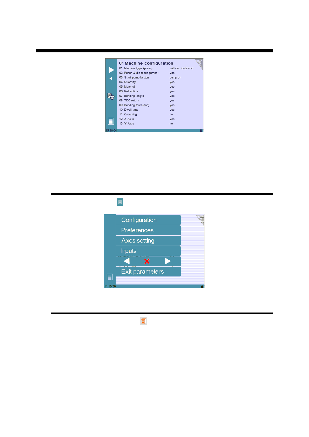
P01 MACHINE CONFIGURATION
This manual explains the functionalities of the CybTouch 6 for conventional
presses, independently of the limits imposed by the hardware and the
subsequent available inputs and outputs.
This manual describes all features of CybTouch 6 P software version 2.0.0
Menu Button
The Menu button will allow you to exit the machine configuration page or to scroll
through the machine parameters pages:
Toggle Pages Button
The Toggle pages button is described in section P02.05 Toggle Pages.
PM_CybTouch6_ PressBrakes_v2.0.doc page 6 of 43
v2.0 Nov. 12
P01.01 Machine Type
Without footswitch: CybTouch doesn’t receive the footswitch
information. It acts as a positioning control. A Machine Ready output
informs the electrical box that the axes are in position. The cycle of the
machine is fully managed by the electrical box.
With footswitch: CybTouch receives the footswitch information.
The CybTouch gives the electrical box orders for the beam to move
down and up (safety must be ensured in the electrical box). This mode
simplifies the electrical box diagram. It also allows the use of timers for
beam travel, as well a valve control feature that allows the valves to
be configured as needed.
PL type: Machine type is PL. This kind of machine uses on-off
valves to move the beam and stop the beam atBDC. A linear encoder
must be mounted on the beam.
P01.02 Punch & Die Management
Set this parameter to Yes to make punch and die management available on the
CybTouch. This also allows the operator to program angle and L with bend allowance.
Set the parameter to No to work without tool management.
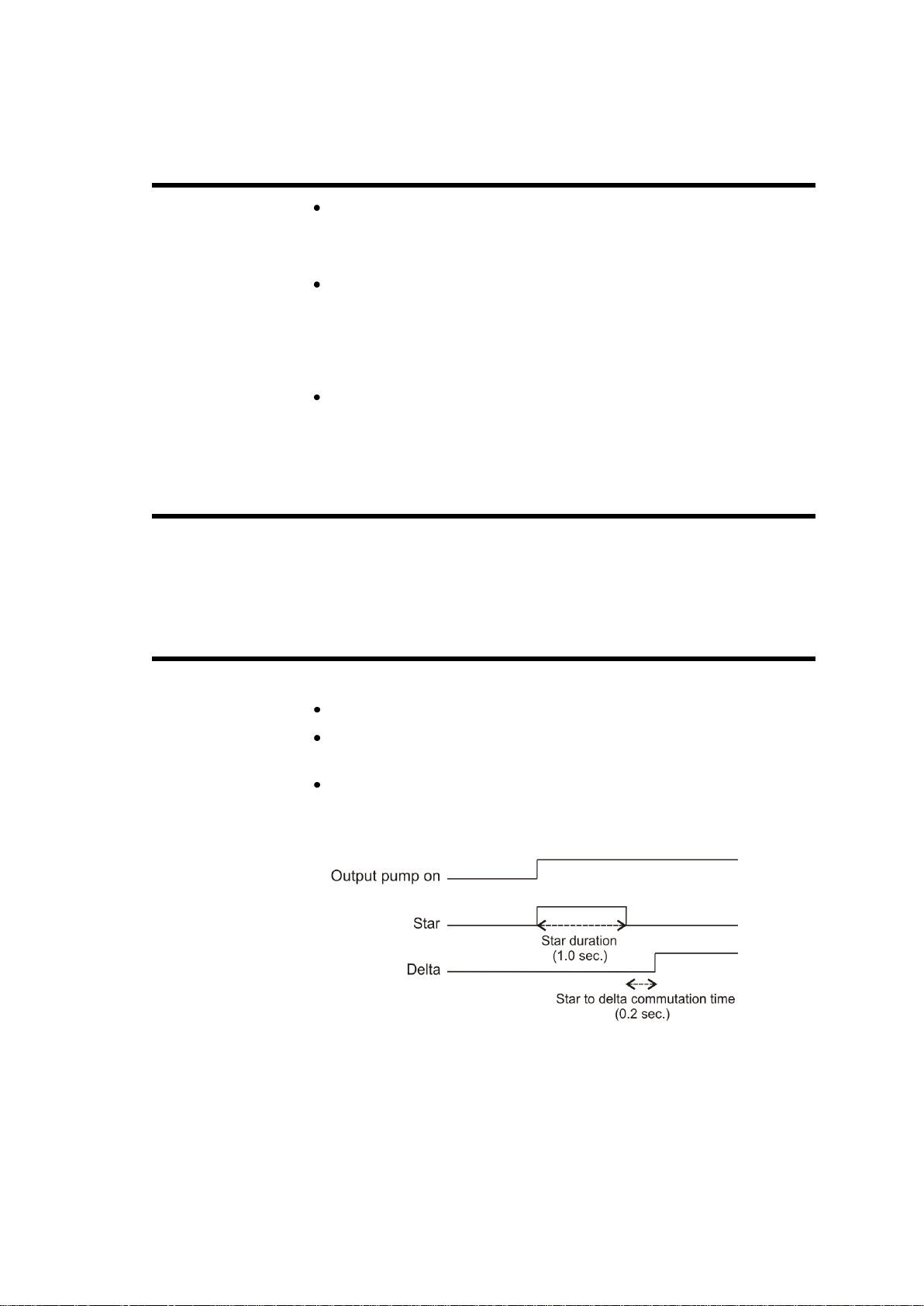
P01.03 Start Pump Button
Touch the Start Pump field to select:
No = Start Pump button is not available on screen.
Yes = Start Pump button is available on screen.
Pump star delta button is available on screen.
1 output (Pump_on) is dedicated to this.
3 outputs are dedicated to the star delta pump start.
1.0s = star duration
0.2s = star to delta commutation time
PM_CybTouch6_ PressBrakes_v2.0.doc page 7 of 43

v2.0 Nov. 12
P01.04 Quantity
The Show quantity function can be enabled or not.
This function allows the operator to enter a number of times a program can be
repeated (number of pieces to be produced).
No: The quantity counter is not displayed.
Yes: The quantity counter is displayed; the operator can enter a
number of pieces to be produced.
P01.05 Material
The Material function can be enabled or not:
No: Material selection is not displayed.
Yes: Material selection is displayed; the operator can select the
material type.
P01.06 Retraction
Set this parameter to No to hide the back-gauge retraction function in the
Bend More page available.
P01.07 Bending Length
Set this parameter to Yes to make the bending length calculation in the Bend
More page available or No to hide it.
If available, when the operator enters the bending length, the CybTouch automatically
calculates the necessary pressure (tools management must be set to yes).
If tool management is set to No, the CybTouch is not able to calculate the tonnage.
The bending length may still available for the operator as bending information only.
The operator will have to program pressure manually.
P01.08 TDC Return
Set this parameter to Yes to make the opening distance in the Bend
More page available, or No to hide it.
If set to Yes, after the decompression the output Return to TDC is active for the
programmed time. This output will activate the up movement of the beam and allow
the operator to adjust the opening depending on their needs.
PM_CybTouch6_ PressBrakes_v2.0.doc page 8 of 43

v2.0 Nov. 12
P01.09 Bending Force
Set this parameter to Yes to make the bending force in the Bend More
page available, or No to hide it.
If available, the operator may enter another bending force as the calculated one.
To calculate the pressure, tools management must be set to yes.
P01.10 Dwell Time
Set this parameter to Yes to make the dwell time function in the Bend
More page available, or No to hide it.
P01.11 Crowning
Set this parameter to Yes to make the crowning function in the Bend More
page available or No to hide it.
When available, crowning can be set as voltage or analog.
Voltage is used to drive a proportional (pressure) crowning valve. Associated
to this mode is the analog output Crowing, available in 3.13 when the default
configuration is set. This analog output (0-10VDC) will be used to drive the
crowning pressure amplifier.
Analog is used for mechanical crowning with potentiometer feedback.
Associated to this mode is one Crowning analog input and 2 digital
Crowning SP and SN outputs, available when the default configuration is set.
P01.12 X Axis
Select whether to configure a X axis or not. Can be temporarily deselected if the
backgauge is not yet mounted on the machine, in order to test the beam functions.
P01.13 Y Axis
Select whether to configure a Y axis or not. Same as above
PM_CybTouch6_ PressBrakes_v2.0.doc page 9 of 43
v2.0 Nov. 12
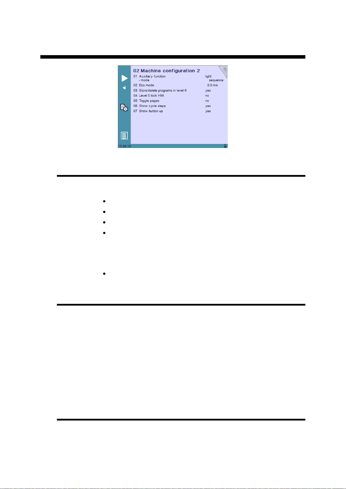
P02 MACHINE CONFIGURATION 2
P02.01 Auxilary Function
A preset auxiliary function can be configured (light) and one or two freely configurable
auxiliary functions can be added: F1 or F1+F2.
None: No auxiliary function configured.
Light: Light is configured.
F1: 1 auxiliary function is configured and called F1.
F1+F2: 2 auxiliary functions are configured, called F1 and F2, and can
be used separately or at the same time.
When auxiliary functions are configured, the below parameter determines if they are to
be applied to the whole machine (on-off on operator use), saved in the complete
program for a specific part, or saved in a sequence in a part.
mode: machine/part/sequence.
P02.02 Eco Mode
The Eco mode parameter defines after how much time of operator or machine
inactivity the CybTouch will switch to economical mode.
When switching into Eco mode the Pump on output is turned off and the screen
becomes darker.
Current value is usually 5-15 min.
Setting the Eco Mode to 0.0 min deactivates Eco mode.
Note: If the Start Pump button is not configured on the screen, but
wired conventionally, the Eco mode off output can be used to
switch off the pump after the Eco mode time is reached. Please refer
to basic electrical diagrams.
P02.03 Store/Delete Programs in Level 0
Here you can choose whether or not operators with access level 0 can be authorized
to store or delete programs in the CybTouch.
PM_CybTouch6_ PressBrakes_v2.0.doc page 10 of 43
v2.0 Nov. 12
P02.04 Level 0 Lock HMI
The Human-Machine Interface can be locked in level 0. This is commonly used when
machines are left unattended on exhibitions to prevent visitors from changing
programs.
When set to Yes, the operator will need a code to access programming (level 2).
The HMI will be automatically locked every time:
The CybTouch is switched off.
After CybTouch switches to Eco mode.
The HMI can be locked manually when you open the menu and press
the padlock icon.
The unlocking code is “55".
(see section Changing Access Level Security Passwords for more details).
P02.05 Toggle Pages
If activated, the toggle button allows you to switch directly from any parameter
page "back" to the last working page visited before accessing the parameters.
Once you are in the working pages, touching allows you to return to the last
accessed parameter page.
This functionality is very useful for technicians during the machine set-up.
Its vivid orange color just informs the technician that this toggle page mode is active
and acts as a reminder to deactivate this functionality before machine delivery.
The Toggle pages button will disappear automatically from operator pages (Toggle
page parameter set to no) after 24 hours of inactivity.
P02.06 Show Cycle Steps
Cycle steps messages at the top of the screen can be displayed or not by activating or
deactivating the Show Cycle Steps parameter.
Ex: .
By default this parameter is set to Yes. The operator immediately knows in which
phase the machine currently is. This feature and the Machine Status pages are very
helpful during the first service calls between the operator and the service engineer.
P02.07 Show Button Up
Select Yes to display the Up
Pressing this button will activate the output Return to TDC until the machine switch
(input TDC) is reached or the button Up released.
button. Select No to hide it.
PM_CybTouch6_ PressBrakes_v2.0.doc page 11 of 43

v2.0 Nov. 12
P03 PREFERENCES
P03.01 Square Signal Low/High
The square signal is used to carry out tests on the machine.
P03.02 Axes Start At
The axes (back gauge) can be configured to start positioning at different moments,
depending on the position of the beam:
BDC if X SP:
BDC: Axes start moving after beam decompression (at BDC).
TDC: Axes start moving when beam reaches TDC.
P03.03 Y axis Delay
This parameter determines the time after which the Y axis begins to move up after
decompression.
o If the axes movement will be in positive direction, axes (back
gauge) will start once the beam reaches BDC.
o If the axes movement will be in negative direction, axes (back
gauge) will wait and start once the beam reaches TDC.
PM_CybTouch6_ PressBrakes_v2.0.doc page 12 of 43
v2.0 Nov. 12
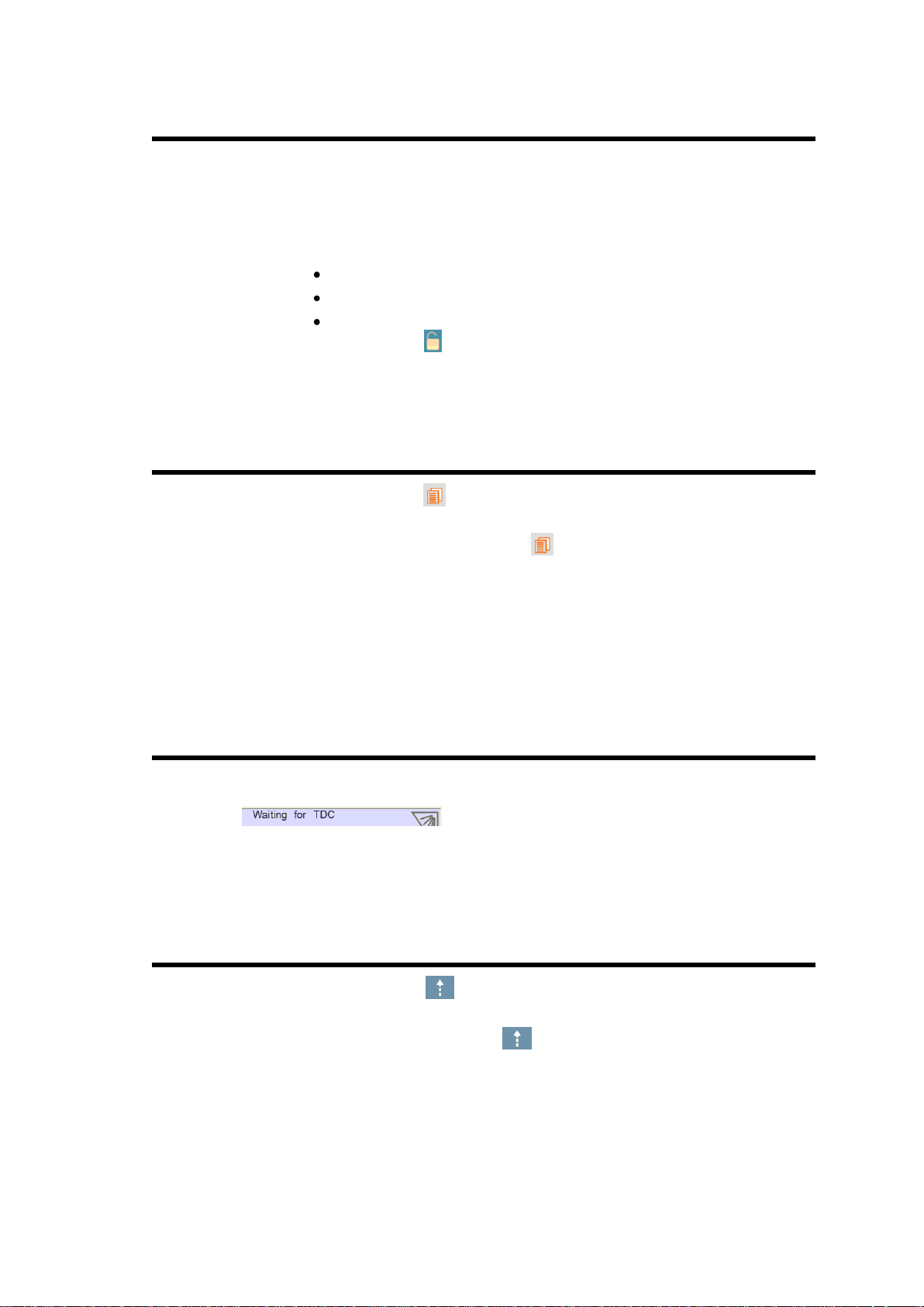
P04 AXIS SETTINGS
Simply touch the –X– or –Y– in the page title to switch from one axis page to the
other.
P04.00 Display Resolution
This value must be entered manually before using the Wizard.
Here you must set the displayed resolution for the selected axis to 0.01 mm,
0.1 mm or 1 mm.
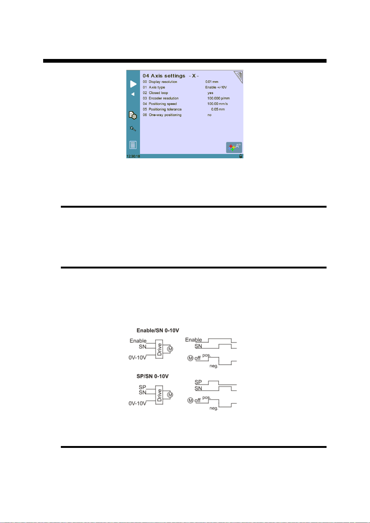
P04.01 Axis Type
This value must be entered manually before using the Wizard.
Depending on the drive logic, you must select either:
For AC brushless motor, select Enable +/-10V.
For frequency converter with asynchronous motor , select either En/SN
0/10V, or SP/SN 0/10V:
P04.02 Closed Loop
Must be set manually before using the Wizard.
If you are using a frequency converter this parameter must be set to No.
PM_CybTouch6_ PressBrakes_v2.0.doc page 13 of 43

v2.0 Nov. 12
P04.03 Encoder Resolution
The encoder resolution can be programmed if it is already known, but can also be
determined using the axis Wizard .
P04.04 Position Speed
Must be set manually before using the Wizard.
Here you must enter an approximate realistic positioning speed for the back gauge.
The real maximum positioning speed will then be determined by the Wizard.
P04.05 Position Tolerance
Must be set manually before using the Wizard.
Here you must enter the position tolerance accepted by the machine for the axis.
P04.06 One-Way Positioning
Back gauge positioning can be configured here. Various configurations are possible;
here are some examples which display how to configure this parameter:
Bi-directional positioning without final approach:
Bi-directional positioning with final approach of 5 mm at 1 mm/s:
One-way positioning with overrun of 30 mm:
PM_CybTouch6_ PressBrakes_v2.0.doc page 14 of 43

v2.0 Nov. 12
One-way positioning with overrun of 30 mm +final approach of 5 mm
and 1 mm/s:
Advanced button
Touching the Advanced button displays the P06b Advanced Axis Regulator
page.
These parameters are automatically generated by executing the Wizard described
below. See section P06b Advanced Axis Regulator X for more details.
Axis Settings -X- Wizard
Important: Before using the Wizard, a number of parameters must be set manually,
see section P06 Axis Settings –X-.
For this example of axis setting, we will enter the below values in the 06 Axis settings
X Page:
Axis type En/SN 0/10V
Closed loop no
Time before 0.0s
Encoder resolution xxxxx p/mm
Positioning speed 60,00 mm/s (*)
One way positioning: no.
(*)Make sure this speed is at least 30 to 40% lower than the expected final speed.
Touch the Wizard button to launch a Wizard to help you set the axis.
Axis movement direction:
1. Program the voltage to a value of minus 30-50%
(30% = auto-tuning will be made with max 3V output. 50% = autotuning done
with 5V output)
2. Simply follow instructions in the Wizard.
3. Follow instructions for the following steps:
Axis resolution.
Axis position test.
Note: if the mechanical position is not right when you measure it,
restart the wizard.
Axis limits.
PM_CybTouch6_ PressBrakes_v2.0.doc page 15 of 43

v2.0 Nov. 12
Axis identification:
1. Set the direction (01 Direction) in which the axis should move. The axis will
move for its identification for a certain time as defined in the next steps. Choose
the axis direction where the most distance is available for the stroke.
2. Set a test voltage (02 Voltage) for axis movement, 2 to 5 V preferably.
Start tests with a small voltage at the beginning in order to observe axis
reaction.
3. Set the duration (03 Time) for axis movement, 2 to 4 sec preferably (but
depending on the axis speed). Start with small value. If too small you will get an
error, if too big, axis may reach mechanical stop.
4. Touch Start,
a. Axis starts a movement with above values, oscillates, stops, and then
returns near to the start position.
b. The Positioning OK message appears and the 10 speed at
10V value is calculated.
Note: P06.04 Positioning speed = 10 Speed at 10 V – 15%.
The P06.04 Positioning Speed can be made lower but never higher.
If an identification error [ ] occurs:
i. Err 1 = No motion detected. Should not happen if you
started the Wizard from the beginning.
ii. Err 2 = Not enough oscillations.
Increase the above identification time.
iii. Err 3= Oscillation amplitude.
Increase the above identification voltage.
iv. In all cases, make sure / verify that the amplifier / frequency
converter don't have internal ramps.
If ramps are set, turn them off (or program them to 0).
v. Make sure that no tests are performed by the drive at start
movement. If set so, turn these tests off (such as the
inductance or poles tests).
PM_CybTouch6_ PressBrakes_v2.0.doc page 16 of 43

v2.0 Nov. 12
5. Touch to move on to Axis Tuning.
Axis tuning:
1. Choose between closed loop and open loop. Keep open loop if frequency
converter is used.
2. Reduce the 04 Positioning speed if needed, never make it higher.
3. Increase or decrease manual speed depending on machine behavior.
4. Increase or decrease acceleration speed depending on machine behavior.
5. Enter a position in the field above and touch START.
6. Verify that X axis went to the right position. Repeat with different values.
Adjust 03 Acceleration to your convenience.
And if necessary set a final approach distance and or the one-way positioning
mode (in P06.06 One-way positioning).
All tests and axis adjustments can easily be made in this page.
After executing the Wizard, the backgauge is set to run in normal operating conditions.
PM_CybTouch6_ PressBrakes_v2.0.doc page 17 of 43

v2.0 Nov. 12
P04B ADVANCED AXIS REGULATOR –X-
Simply touch the –X– or –Y– in the page title to switch from one axis page to the
other (depending on the axes configured in P01 Machine Configuration).
All parameters in this chapter are automatically calculated by the Wizard.
P04b.01 Change Counting Direction
This parameter changes the counting direction for the axis movement/positioning.
P04b.02 Manual Speed
This parameter determines the manual movement speed for the axis in mm/sec.
P04b.03 Acceleration
This parameter determines the X axis default acceleration speed.
The bigger the value is, the faster the acceleration is.
P04b.04 Invert voltage & Speed at 10V
Theoretical maximum speed of the axis with 10V applied to the drive.
This value is set by the Wizard and should be handled manually with great care, or
simply left to be calculated by the Wizard.
The sign in front of the value (+ or -) shows inversion or not.
P04b.05 Closed Loop Frequency
This parameter determines the level of proportional gain. This value is set by the
Wizard and should be handled manually with great care, or simply left to be
calculated by the Wizard.
PM_CybTouch6_ PressBrakes_v2.0.doc page 18 of 43

v2.0 Nov. 12
P04b.06 Integrator factor
Integral gain. This value is set by the Wizard.
Can be adjusted manually to increase positioning accuracy.
P04b.07 Offset Voltage
Offset voltage, 0 - 9.999V
P04b.08 Supervisor Error
Supervisor error 0 - 999.99 mm
999.99 = no test
Usually programmed:
10 - 30 mm with frequency converter and
5-10 mm with servo-drives.
This is the max allowed distance between the calculated and the real trajectory.
If during movement the value in P06b.08 Supervisor error is exceeded, the
NC stops the movement and displays FW Err 32 Trajectory following
error. Try to slow down the positioning speed and or acceleration, or check that the
axis has no mechanical friction spots on its stroke.
P04b.09 Supervisor Speed Level
Speed supervisor level 100%.
0 = no test.
Usually programmed:
20-30% with frequency converter and
5-10 % with servo-drives.
This is the max. allowed speed difference between the calculated and the real
speed.
If during movement speed difference exceeds the value in P06b.09 Supervisor
speed level, the NC stops the movement and displays FW Err 39 Speed
following error.
Try to slow down the positioning speed and/or acceleration, or check for friction
points on the axis stroke.
P04b.10 Control Time Out
Control time out 9.999s
0 = no test
Usually programmed
0.4 to 0.8s with frequency converter, and
0.2 -0.4s with servo-drives.
This is the max allowed time with regulator at max voltage.
If this error appears, it means the regulator had to provide 10V for at least the
duration programmed in this parameter.
If at start and during movement, the value in P06b.10 Control time out is
exceeded, the NC stops the movement and displays FW Err 33 Maximum
voltage time exceeded.
PM_CybTouch6_ PressBrakes_v2.0.doc page 19 of 43
v2.0 Nov. 12
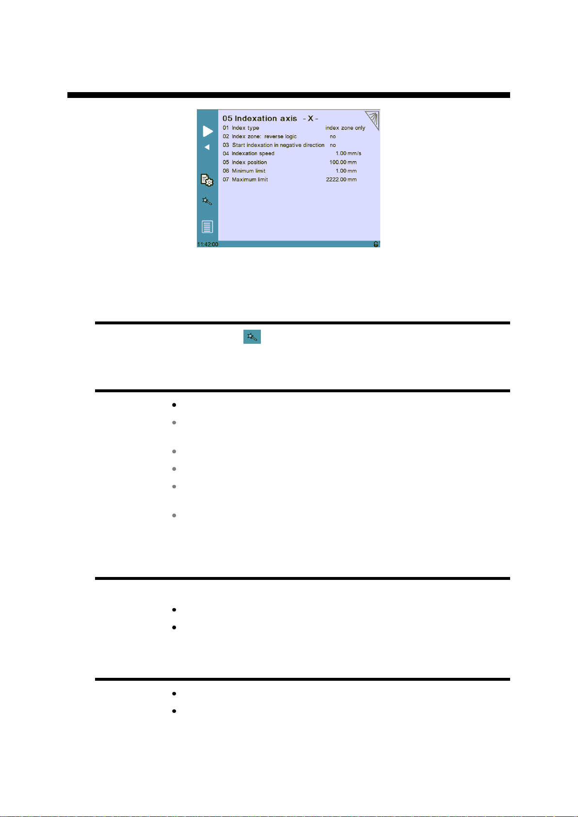
05 INDEXATION AXIS -X-
Simply touch the –X– or –Y– in the page title to switch from one axis page to the
other (depending on the axes configured in P01 Machine Configuration).
Indexation Axis -X- wizard
Touch the wizard button to index the axis X using the wizard:
P05.01 Index Type
None: No indexation.
Index and zone: Axis indexes to the index zone, and then to the
index.
Index only: The axis indexes only to the index.
Index zone only: The axis indexes only within the index.
Mechanical stop: There is no existing index zone or index. The index
is taken from the position of the mechanical stop.
Mechanical and index: The axis reaches a mechanical stop and
then indexes.
P05.02 Index Zone: Reverse Logic
Indexation to zone is performed with index zone signal inverted:
Yes: Active at 0V.
No: Active at 24V.
P05.03 Start Indexation in Negative Direction
Yes: Axis starts indexing in negative direction.
No: Axis indexes in positive direction.
PM_CybTouch6_ PressBrakes_v2.0.doc page 20 of 43

v2.0 Nov. 12
P05.04 Indexation Speed
Enter the indexation speed for the back gauge in mm/sec.
P05.05 Index Position
Enter the index position or measure it with the wizard.
P05.06 Minimum Limit
Enter the minimum limit position or measure it with the wizard.
P05.07 Maximum Limit
Enter the maximum limit position or measure it with the wizard.
PM_CybTouch6_ PressBrakes_v2.0.doc page 21 of 43

v2.0 Nov. 12
06 AXIS FUNCTIONS -X-
Simply touch the –X– or –Y– in the page title to switch from one axis page to the
other (depending on the axes configured in P01 Machine Configuration).
P06.01 Speed with Input “Speed Reduction”
One input named Speed reduction allows the positioning speed of the axis to be
reduced. Enter here the speed when the input is active.
PM_CybTouch6_ PressBrakes_v2.0.doc page 22 of 43
v2.0 Nov. 12
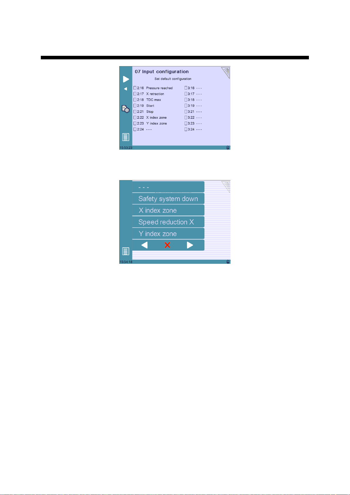
07 DIGITAL INPUT CONFIGURATION¨
The input configuration can be modified according to the machine requirements here.
Simply touch a non-configured input and select the output to configure in the list:
Note: Use the arrows to scroll through the available inputs.
Doubling inputs will result in an error (configuration error) occurring when you
leave the machine parameters page.
PM_CybTouch6_ PressBrakes_v2.0.doc page 23 of 43

v2.0 Nov. 12
INPUT
RECEIVED SIGNAL
Safety system down
Informs the NC that safety system is deactivated. A
popup message will appear.
Y index zone
Y axis (beam) has reached its index zone.
X index zone
X axis (back gauge) has reached its index zone.
Speed reduction X
Forces X axis speed to P06.01 Speed with input “Speed
reduction”.
Enable Y
If configured, this input must be active in order to allow Y
axis movement. This is generally used as a safety
measure for Y axis (a switch which detects a minimum
distance between the depth gauge and the beam).
Next Seq+Start
Move to next sequence and Start.
Stop
Stops the movements.
Start
Starts the movements.
Pressure reached
Pressure has been reached (at BDC).
X retraction
Start X axis (back gauge) retraction.
TDC Max
Beam has reached TDC Max position.
Available digital inputs for configuration:
PM_CybTouch6_ PressBrakes_v2.0.doc page 24 of 43
v2.0 Nov. 12
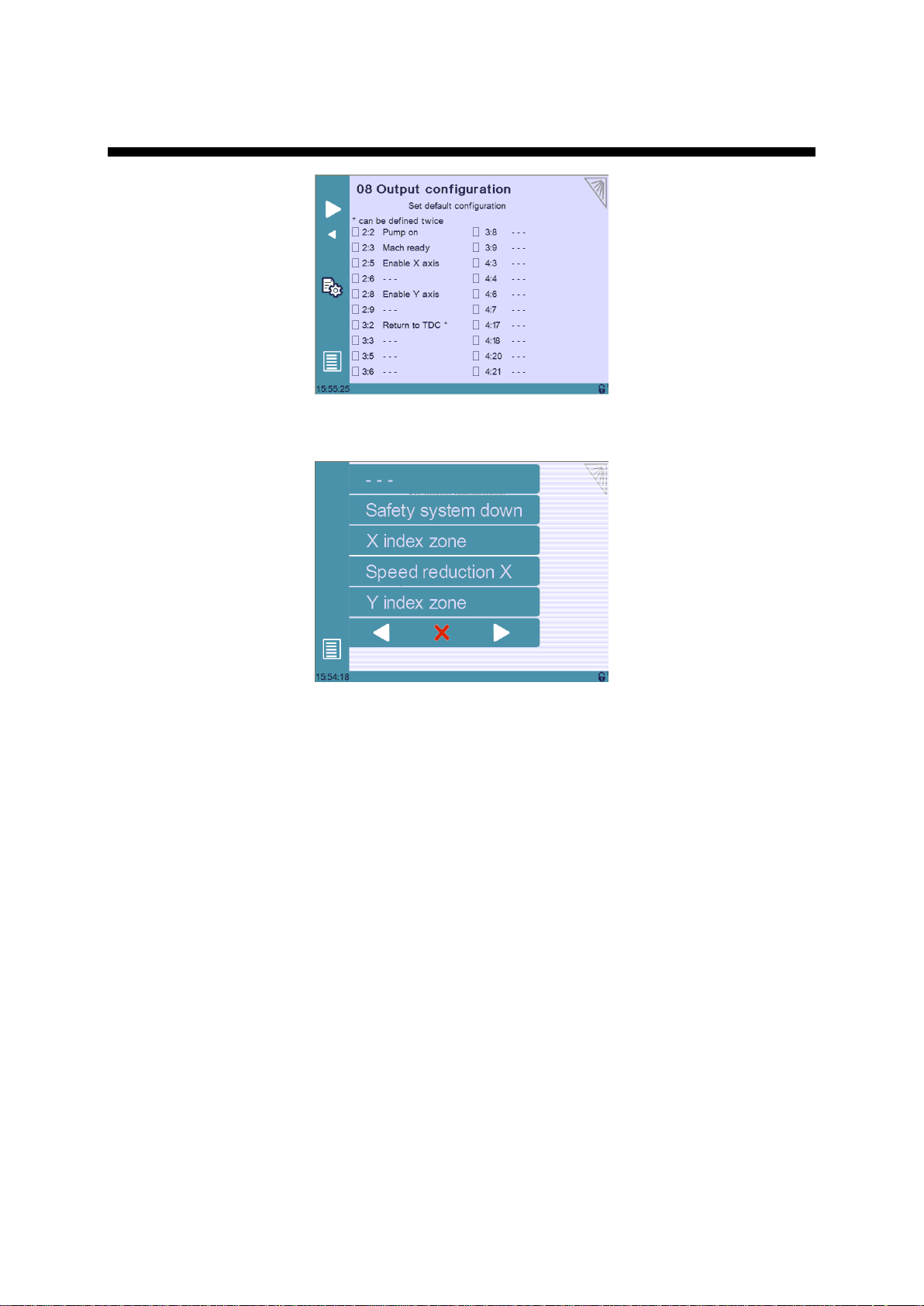
08 DIGITAL OUTPUT CONFIGURATION
The output configuration can be modified according to the machine requirements here.
Simply touch a non-configured output and select the output to configure in the list.
Note: Use the arrows to scroll through the available outputs.
Some outputs can be doubled for more power. Simply configure the output twice to
double it. Only the outputs marked with a * can be doubled.
Doubling an output that isn’t marked with a * will result in an error (configuration
error) occurring when you leave the machine parameters page.
PM_CybTouch6_ PressBrakes_v2.0.doc page 25 of 43

v2.0 Nov. 12
OUTPUT
SENT SIGNAL
Pump on
Turns on pump.
Enable X axis
Signal to allow X axis movement.
X moving
This output is active when X axis is moving.
Enable Y axis
Signal to allow Y axis movement.
Square signal
Square signal for external use (P03.01).
Safety system reset
Can be used to reinitialize the safety system (impulse).
Eco mode off
Deactivates Eco mode (P02.01)
Mach ready
Machine is ready to move.
Return to TDC
Move beam up to TDC.
Crowning SP
Moves the crowning system up.
Crowning SN
Moves the crowning system down.
Mach indexed
Axes are indexed.
Decompression
Output active during decompression phase.
TDC Max
Output active when beam is considered to be at TDC
Max.
Aux funct F1
Output for auxiliary function F1
Available digital outputs for configuration:
PM_CybTouch6_ PressBrakes_v2.0.doc page 26 of 43

v2.0 Nov. 12
ANALOG INPUT
RECEIVED SIGNAL
Crowning
Potentiometer feedback of the crowning system
ANALOG OUTPUT
RECEIVED SIGNAL
X axis
X axis analog output.
Y axis
Y axis analog output.
Pressure
Pressure analog output.
10V ref.
10 V reference for crowning potentiometer feedback
ENCODER
RECEIVED SIGNAL
Y axis
Y encoder.
X axis
X encoder.
09 ANALOG I/O CONFIGURATION
The analog inputs or outputs may be modified according to the machine requirements.
Simply touch a field and select the output to configure.
Available analog outputs for configuration:
Available analog inputs for configuration:
Encoder signals:
PM_CybTouch6_ PressBrakes_v2.0.doc page 27 of 43

v2.0 Nov. 12
10 PRESSURE
To configure pressure, P01.09 Bending force parameter must be set to Yes.
The above 8 points table allows the pressure valve reaction to be "linearized". None,
some, or all table points (2-7) may be used for this function.
Usually the first line starts at 0 and last column is set to 100 %.
The second line defines the output voltages for the pressure valve at pressure X.
The crowning line appears only if crowning is configured.
In the crowning line, the manufacturer enters the crowning values (mm) that will be
automatically set by default regarding the pressure in the sequence’s More page.
In this table, the NC calculates a straight interpolation between 2 points.
The Wizard helps adjusting the pressure. Simply run it and follow its instructions.
P10.01 Max Tonnage
Determines the maximum tonnage of the machine.
P10.02 Min Tonnage
Determines the minimum tonnage the machine needs to run correctly.
P10.03 HS Down Pressure
Determines the pressure applied when moving the beam down.
P10.04 LS Down Pressure
Determines the pressure applied when moving the beam down at low speed.
P10.05 Up Pressure
Determines the pressure applied when moving the beam up.
PM_CybTouch6_ PressBrakes_v2.0.doc page 28 of 43

v2.0 Nov. 12
P10.06 Decompression Pressure
Pressure applied during the decompression phase.
P10.07 Decompression Time min/max
Duration of the decompression for minimum and maximum pressure.
P10.08 Acceleration/Deceleration Time
This is time applied at change speeds.
PM_CybTouch6_ PressBrakes_v2.0.doc page 29 of 43

v2.0 Nov. 12
11 CROWNING
To configure crowning, P01.08 Bending force and P01.10 Crowning
parameter must be set to Yes.
The crowning is simply setup using the wizard. The objective here is to have the
crowning as linear as possible with the voltage.
This page only serves to set up the crowning movement.
Voltage Crowning
The wizard and P11.01 to P11.05 parameters are not available in voltage mode.
Crowning voltage defines a hydraulic crowning managed with a proportional valve and
a 0-10 V analog output voltage from the CybTouch.
In the first line the voltage output to the crowning valve is set / taught.
In the second line the crowning position with the corresponding voltage pressure is
programmed.
If the crowning device should not be linear, the manufacturer can add intermediate
points (2-7) to "linearize" the movement.
Analog Crowning
The wizard and P11.01 to P11.05 parameters are only for analog crowning.
Analog crowning is a mechanical crowning, which gives a feedback position with a
potentiometer.
In the first line the voltage feedback of the potentiometer at mechanical minimum
position (ex. 1.65V/0.01mm) and maximum position (5.94V/1.45 mm) is set.
If the crowning device should not be linear, the manufacturer can add intermediate
points (2-7) to "linearize" the movement.
PM_CybTouch6_ PressBrakes_v2.0.doc page 30 of 43

v2.0 Nov. 12
Crowning Wizard
Touch the wizard button . Follow the instructions on screen and touch . The
wizard will calculate the min. and max. values and intermediate points.
P11.01 Inverted AD Input (only crowning analog)
This parameter allows the sensor signal to be inverted. If increasing the voltage signal
causes the device to move in negative direction, this can be fixed by setting this
parameter to Yes (or exchanging the potentiometer wiring).
P11.02 Tolerance
Tolerance for crowning positioning.
To avoid problems, the tolerance value must be bigger than the P11.03 Advanced
stop parameter.
If there is a programmed P11.04 Overrun distance, the tolerance value may be
programmed at smaller value than the advanced stop.
P11.03 Advanced Stop
The advanced stop parameter for crowning movement.
P11.04 Overrun Distance
Overrun distance for positioning the crowning. 0.00 mm= no overrun.
P11.05 SN/SN Time
This parameter determines the time required to switch from a positive movement to a
negative movement while the axis makes the overrun in a unidirectional movement.
0 s = not in use.
PM_CybTouch6_ PressBrakes_v2.0.doc page 31 of 43

v2.0 Nov. 12
12 BEAM 1 (ONLY WITH FOOTSWITCH)
P12.01 Low Speed
Indicates the CybTouch bending speed.
This value has to be entered as accurately as possible. The CybTouch is using it to
calculate the bending time (T1).
P12.02 Min Bending Time
This time is the minimum time for the bending time.
P12.03 Default BDC
This is the default time that will be applied to the beam (if the operator didn’t program
any other value in the sequence (More) pages.
PM_CybTouch6_ PressBrakes_v2.0.doc page 32 of 43

v2.0 Nov. 12
13 BEAM 2 (ONLY WITH FOOTSWITCH)
P13.01 Machine Correction T1 T2
Must be set to Yes to have the T1/T2 timer functions.
If activated, the CybTouch waits for the change speed switch.
At change speed switch the timer T1 starts.
At the end of timer T1, the retraction starts (if configured). T1 determines the pinch
point.
At end of timer T1, the timer T2 starts,
T2 is calculated with the speed of parameter P12.01 Bending speed.
At end of T2 dwell time starts and the return of stroke begins.
The operator can correct these values (T1, T2) on the working pages.
Time Switch point – Pinch point (T1)
This table is only used with machine correction T1/T2 = yes.
This table adjusts the timer T1 relatively to the material thickness.
The thicker the sheet metal is, the shorter the time is. The different columns (2-7)
allow intermediate points to be set for a better accuracy.
PM_CybTouch6_ PressBrakes_v2.0.doc page 33 of 43
v2.0 Nov. 12
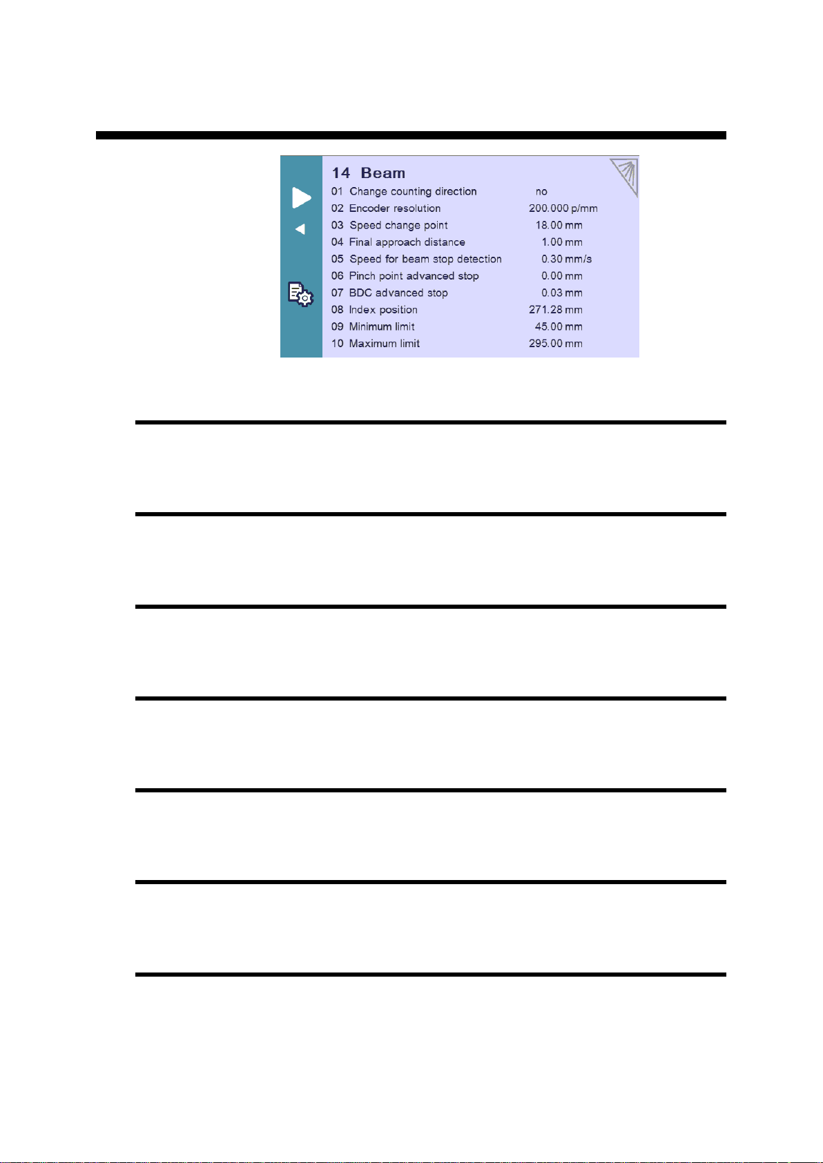
P14 BEAM (PL MODE ONLY)
P14.01 Change Counting Direction
Change Y axis counting direction.
P14.02 Encoder Resolution
Define the resolution for the Y (beam) encoder.
P14.04 Final Approach Distance
Enter the final approach distance for the beam.
P14.05 Speed for Beam Stop Detection
This is the speed at which the beam is considered by the NC to have stopped moving.
P14.06 Pinch Point Advanced Stop
Defines the advanced stop before the pinch point (if needed).
P14.07 BDC Advanced Stop
Defines the advanced stop before the BDC.
P14.08 Index Position
This is the index position.
PM_CybTouch6_ PressBrakes_v2.0.doc page 34 of 43

v2.0 Nov. 12
P14.09 Minimum Limit
Minimum limit for beam position.
P14.10 Maximum Limit
Maximum limit for beam position.
PM_CybTouch6_ PressBrakes_v2.0.doc page 35 of 43

v2.0 Nov. 12
P15 VALVES CONTROL
On this page the parameters for controlling the valves can be configured.
Touching the padlock icon locks or unlocks the fields in the table.
PM_CybTouch6_ PressBrakes_v2.0.doc page 36 of 43

v2.0 Nov. 12
Access
level
Description
Default
Notes
0
Unlock touchscreen when
locked in level 0.
55
If machine parameter P03.04 HMI
locked in level 0 is set to Yes
1
Access to programs
111
Only if the machine parameter
P03.03 Store/Delete programs
in level 0 is set to Yes
2
Access Service
222 3
Access Machine parameters
333
4
Supervisor access level
*
Supervisor level of access allows the
access levels 1, 2 and or 3 to be
modified. It cannot be modified.
5
Reset the HMI password (for
blocking the touchscreen)
*
This password resets the HMI
password to the default password.
Only works If machine parameter
P03.04 HMI locked in level 0 is
set to Yes
Internal
backup
Create an internal backup for
data
*
Internal backup is created in a specific
area of CybTouch memory
Restore
Restore using internal backup
*
Restores data from the internal backup
on CybTouch memory
CHANGING ACCESS LEVEL SECURITY PASSWORDS
Default Passwords
For each access level there is a default password:
* Please ask for level 4 and 5 passwords by phone or email to support@cybelec.ch.
Changing Passwords
Access level 4 is required to modify all access level passwords:
7. Go to the machine parameters and enter the password level 4.
8. Now touch the Menu button and scroll through the pages using or
until the below page appears with Passwords:
Important: Once a password is modified it is no longer possible to
return to the default password, except the HMI lock (touchscreen
locked in level 0 access).
If a password is forgotten/lost the only way to continue is to modify the
password again in Supervisor mode.
PM_CybTouch6_ PressBrakes_v2.0.doc page 37 of 43

v2.0 Nov. 12
9. Touch Passwords and select the password you wish to change:
10. Enter the new password with the numerical keypad and validate. Enter the new
password again to confirm. The message Password accepted is displayed
in the interactive message line if the password was changed successfully.
Note: The new passwords must all be unique and must not be the same as the default
passwords described above.
PM_CybTouch6_ PressBrakes_v2.0.doc page 38 of 43

v2.0 Nov. 12
CREATING BACKUPS AND RESTORING DATA
Creating an Internal Backup of Machine Parameters
After setting up the machine, the tachnician must create an in internal backup in the
CybTouch for the machine parameters. This is used if there is a problem with the
CybTouch to reset the machine paremeters. Code level 3 and the backup code are
required for this (817).
This is done via the Maintenance page, in the Service Menu:
1. Touch the Menu button
2. Touch Services.
3. Touch Services again.
4. Touch Maintenance.
5. Touch Internal backup.
6. Enter password level 3.
7. Touch Backup.
8. Enter the backup password (817).
9. Touch Internal backup again.
10. Touch Backup again.
11. Validate to create the backup.
Restoring Creating an Internal Backup of Machine Parameters
The end user will request the assistance of a technician to restor machine parameters
if there is a problem with the CbTouch. This is why code level 2 (not 3) and the restore
code 718 (inverted 817 password) are required foer this.
This is done via the Maintenance page, in the Service Menu:
1. Touch the Menu button
2. Touch Services.
3. Touch Services again.
4. Touch Maintenance.
5. Touch Internal backup.
6. Enter password level 2.
7. Touch Restore.
8. Enter the backup password (718).
9. Touch Internal backup again.
10. Touch Restore again.
11. Validate to restore machine parameters.
PM_CybTouch6_ PressBrakes_v2.0.doc page 39 of 43

v2.0 Nov. 12
WARNING MESSAGES
15 //Input detected while in
programming mode!
The "Next Seq+Start" or the "Pressure reached" input is activated while
NC is in programming mode. If the message persists, check the machine
status.
18 //Empty field
Operator did not enter a value.
19 //24V I/O power on
24V to the inputs/outputs is now available.
32 //Data entry in progress
Operation impossible: data entry in progress
35 //Access not allowed
Operator needs another level password.
37 //Moving direction has
been inverted
Wizard msg.: Rotary direction of the motor has been changed.
38 //Counting direction has
been inverted
Wizard msg.: Counting direction of the axis has been changed.
39 //Moving and counting
directions are inverted
Wizard msg.: Both the rotary direction of the motor and the counting
have been changed.
41 //No movement executed
Wizard msg.: Operator pressed but movement was not made.
ERROR MESSAGES
03 //Buffer Full
The part-program memory is full, you cannot add another sequence.
04 //Code refused
The level code to access the selected page is not correct. Ask for it.
05 //File not compatible
The loaded part-program is incompatible with the NC. This part should
be deleted.
06 //Machine parameter file
problem
This file is corrupt and cannot be saved. Try to restart the NC. If the
problem persists, format the memory.
07 //Machine parameters not
compatible, please format
data
If a software update has been made over a much older version, perhaps
the parameters are no longer compatible. Or if uploaded parameters
(with RFlink) are much older or newer than the current software version,
they also may not be compatible. A new start up of the machine must be
made. Contact your dealer.
08 //Lismisc File not
compatible
Information message, will disappear upon next NC restart.
09 //Save program problem
This file is corrupt and cannot be saved. Try to restart the NC. If the
problem persists, format the memory.
11 //Write to file problem
This file is corrupt and cannot be saved. Try to restart the NC. If the
problem persists, format the memory.
ERROR AND WARNING MESSAGES IN CYBTOUCH 6
FOR PRESS-BRAKES
Below is a list of warning and error messages which may be displayed on the
interactive message line the CybTouch. Each message is explained and possible
solutions are provided:
Warning messages are on a green background, and are information or
instructions that will disappear automatically.
Error messages (machine or NC errors) are on a red background. They inform
the user of an error occurring on the machine or NC, and sometimes require
intervention by the end user or a technician.
PM_CybTouch6_ PressBrakes_v2.0.doc page 40 of 43

v2.0 Nov. 12
12 //X smaller than minimum
limit
Operator entered a value under the limit, or a memorized value in the
program is under the limit. Change value.
13 //X over maximum limit
Operator entered a value over the limit, or a memorized value in the
program is over the limit. Change value.
14 //Fw SetVar Error
May occur when a feature is configured, but the dedicated in–output is
not configured. Usually this is solved by loading the default in-output
configuration.
17 //Programming error
Machine parameters incorrectly configured, the error page is displayed.
20 //Cycle repeat = 0
Cannot start cycle because repeat cycle function is set to “0”.
21 //No material defined
(define one or more in
Materials page)
No materials programmed in the Material pages (in User preferences). A
material must be selected to perform calculations.
25 //No FAST task running [ ]
Switch OFF the machine for 1 min and restart again.
28 //No I/O 24V or overload
(output in safety off)
Inputs/outputs 24V power supply is no longer present or an output is
overloaded. Reset any safety device on the machine, check protection
grids and rear guards are closed, etc. If problem persists, switch
machine OFF for 3 min and restart again. If problem still persists, check
the machine manual and/or ask a service technician to check your
machine.
30 //Touch Screen error,
code [ ]
Please contact your machine dealer with this specific code and details.
31 //"Crowning" analog input
not configured
While configuring (setting up) the NC, dedicated input or output are not
configured but are requested to run properly.
32 //"Crowning" analog
output not configured
While configuring (setting up) the NC, dedicated input or output are not
configured but are requested to run properly.
33 //Syntax error in XML file
This file is corrupt and cannot be used. Try to restart the NC. If the file is
a part-program, try to delete it.
35 //Endless loop on process
task
Process error. Please restart the NC and inform your dealer.
39 //"Start" input refused
The start command is not accepted in this page/situation
43 //Configuration error
Input/output incorrectly configured in machine parameters, the error
input/output page is displayed.
44 //"External stop" input is
active
External stop may be caused by safety devices, emergency buttons,
rear protection guards, etc. See machine instructions.
46 //"Pressure" analog
output not configured
While configuring (setting up) the NC, dedicated input or output are not
configured but are requested to run properly.
55 //Identification Error 1 (No
motion detected)
No motion detected. Should not happen if you started the Wizard from
the beginning. If the error remains, check limit switches, drive, wiring,
etc.
56 //Identification Error 2
(Not enough oscillations)
Not enough oscillations Increase the identification time. See machine
parameters manual.
57 //Identification Error 3
(Amplitude of the oscillation)
Oscillation amplitude. Increase the identification voltage. See machine
parameters manual.
PM_CybTouch6_ PressBrakes_v2.0.doc page 41 of 43

v2.0 Nov. 12
58 //Fw Axes Error 32
[Trajectory tracking error]
This is a regulator error. The axis could not follow its trajectory. This may
be due to high friction, resistance or an obstacle on the axis movement.
This may also be a drive problem.
The parameter P06b.08 Supervisor error monitors whether the axis
can follow the trajectory.
If the error between the theoretical (requested) trajectory and the real
trajectory (position of the axis) is more than xx mm, the CybTouch stops
and displays FW Axes Error 32.
Try adjusting speed and acceleration (generally by reduce P06.04
Positioning speed and P06b03 Acceleration.).
Usually this parameter can be set to 10 mm. It can be increased if
needed, but the correct way is to adjust the axis and reduce acceleration
and speed.
Tip: To adjust the speed, we recommend that you use the axis Wizard. If
the speed found by the Wizard is too high, it can safely be reduced, but
must NEVER be increased.
59 //Fw Axes Error 311
[MaxSpeed too high !]
Max speed or encoder resolution too high.
60 //Fw Axes Error 312
[MaxSpeed too small !]
Max speed or encoder resolution too low.
61 //Fw Axes Error 313
[Acceleration too small or
MaxSpeed too high !]
Acceleration too low (mm/s²) or max speed too high. This needs to be
corrected. Please note that acceleration is not a ramp distance.
62 //Fw Axes Error 314
[Acceleration too high or
MaxSpeed too small !]
Acceleration too high (mm/s²) or max speed too low. This needs to be
corrected.
66 //Fw Axes Error 33
[Maximum voltage time
exceeded (10V)]
This is a regulator error. The axis could not follow its trajectory. May be
due to higher friction, resistance or an obstacle on the axis movement.
May also be a drive problem.
The parameter P06b.10 Control time out is the maximum time that the
regulator is allowed to give the maximum voltage.In this example, the
parameter is set to 0.1 s. This means if the regulator gives 10V for more
than 0.1 sec, the CybTouch will stop and display FW Axes Error 33.
This error means the axis cannot follow the trajectory programmed in the
machine parameters (acceleration and speed). So the regulator gives
10V to try to make the axis follow. Try to reduce the Positioning speed
P06.04 and or reduce the Acceleration P06b.03. To avoid excessive
errors program this parameter to 0.2 / 0.3 sec, or even 0.5 sec.
Tip: To adjust speed, we recommend you use the axis Wizard. If the
speed found by the Wizard is too high, it can safely be reduced, but
must NEVER be programmed higher.
PM_CybTouch6_ PressBrakes_v2.0.doc page 42 of 43

v2.0 Nov. 12
67 //Fw Axes Error 39
[Speed tracking error]
This is a regulator error. The axis could not follow its trajectory. May be
due to higher friction, resistance or an obstacle on the axis movement.
May also be a drive problem.
The parameter P06b.09 Supervisor speed level monitors whether the
axis can follow the programmed speed. If the speed is less or more than
xx% of the P06.04 Positioning speed, the CybTouch stops and
displays FW Axes Error 39.
This means the axis could not follow the programmed speed.
Try to adjust speed correctly (by reducing P06.04 Positioning speed).
Usually this parameter can be set to 20%. It can be increased if needed,
but the correct way is to adjust the axis correctly and reduce the speed.
Tip: To adjust the speed, we recommend you use the axis Wizard. If the
speed found by the Wizard is too high, it can safely be reduced, but
must NEVER be programmed higher.
69 //The machine is not
indexed ! No limit
Before the machine is indexed, the NC doesn’t know where the axes
are. In manual page, movements are authorized but the electronic stroke
limits are not activated. Operator is responsible for stopping axis
movement before mechanical limit is reached.
80 //Progr. angle is smaller
than the die angle
The programmed angle is smaller than the die angle. Change die.
81 //Progr. angle is smaller
than the punch angle
The programmed angle is smaller than the punch angle. Change punch.
82 //Depth safety
The calculated angle causes the punch, material, and die to collide and
approach coining mode. Operator must confirm to proceed.
Error 115
Error 115 is a "parasite" problem. This error can occur if:
the frame of the CybTouch is not connected to the ground.
the 0VDC_IO is not well connected.
the 0VDC_IO is wired in serial when it should be wired in star.
See wiring recommendation in the technical manual:
This error may be also caused by spikes coming from unprotected
valves or if the 0V_analog is connected to the 0VDC_IO or CybTouch
frame or machine ground.
PM_CybTouch6_ PressBrakes_v2.0.doc page 43 of 43
 Loading...