

Page 1

User Manual
for Synchronized Press Brakes
Febr.’15
V2.0
Page 2

© 2015 Cybelec S.A.
All Rights Reserved
Copying, reproduction, modification, distribution, display or transmission of any of the contents of
this manual for any purpose without the prior consent of Cybelec S.A. is strictly prohibited.
Page 3

The Intuitive Programming
Table of conTenT
Safety ......................................................................................................................1
General Safety ............................................................................................................................... 1
ModEva with Windows Operating System .................................................................................. 2
Signs and Icons appearing in this Manual .................................................................................. 3
General warning ............................................................................................................................. 3
Information.................................................................................................................................... 3
Settings .......................................................................................................................................... 3
Navigation .................................................................................................................................... 3
Getting started with ModEva 15T ............................................................................ 4
Screen Cleaning .............................................................................................................................. 4
General navigation ....................................................................................................................... 5
Menu Button ................................................................................................................................ 5
List of Products ................................................................................................................................................. 5
Graphical List of Products ...............................................................................................................................5
Search of Product/Criteria .............................................................................................................................. 6
List of Punches ..................................................................................................................................................6
Programming of Punches ................................................................................................................................6
Transfer .............................................................................................................................................................6
List of Dies ........................................................................................................................................................6
Programming of Dies .......................................................................................................................................6
Welcome ............................................................................................................................................................7
Machine Parameters ......................................................................................................................................... 7
Machine Initialization DNC/ENC ................................................................................................................... 7
Control .............................................................................................................................................................. 7
Product Button ............................................................................................................................... 8
TouchProfile .....................................................................................................................................................8
Product 3D ........................................................................................................................................................ 8
Comment ..........................................................................................................................................................8
Page 4

The Intuitive Programming
Product Numerical ........................................................................................................................................... 8
Tools Position .................................................................................................................................................... 8
Bend Button ................................................................................................................................... 9
Bend Numerical ................................................................................................................................................9
Bend 3D ............................................................................................................................................................9
Bend 2D ............................................................................................................................................................9
Image Bend ....................................................................................................................................................... 9
Correction Button ...........................................................................................................................10
Bend Function ................................................................................................................................................ 10
Corrections .....................................................................................................................................................10
Tools Bend ......................................................................................................................................................10
Actions Button ..............................................................................................................................11
Language .....................................................................................................................................11
Tools Position .......................................................................................................12
Punch Adjustment ...................................................................................................................... 12
Die Adjustment ........................................................................................................................... 13
Adding Working Stations ........................................................................................................... 14
Creating a Part Program ........................................................................................15
TouchProfile Programming ....................................................................................................... 16
Special functions for a bend .............................................................................................................17
L-Alpha Programming ............................................................................................................... 18
3D Programming (optional) ..................................................................................................... 19
Bend 2D Page ............................................................................................................................. 21
Bend Numerical Page (Direct Programming) ......................................................................... 22
Position of axes and other functions ..................................................................................................23
Bending, Tests and Corrections................................................................................................. 24
Memorize or Search a Program .............................................................................26
Memorize a Program .................................................................................................................. 26
From the List of Product page ...........................................................................................................26
Page 5

The Intuitive Programming
Search a Product ........................................................................................................................ 27
Standard Method ...........................................................................................................................27
Rapid method ................................................................................................................................27
Graphic Method .............................................................................................................................28
Sorting Products ............................................................................................................................................. 28
Searching a product .......................................................................................................................................28
Protection of the Access Levels .............................................................................29
General Information .................................................................................................................. 29
Levels ...........................................................................................................................................29
Access ...........................................................................................................................................29
Password ......................................................................................................................................29
Characteristics ...............................................................................................................................29
Loss of the password .......................................................................................................................29
Users ............................................................................................................................................ 30
Access by Password ..................................................................................................................... 31
Access to Levels Superior to 3 ................................................................................................... 31
Change Passwords ...................................................................................................................... 32
Forgotten Passwords ................................................................................................................... 33
Cybelec Software ...................................................................................................34
Installing the Software ............................................................................................................... 34
Leaving the Software .................................................................................................................. 34
Page 6

The Intuitive Programming
Page 7
ModEva 15T User Manual
Safety
General SafeTy
The users must have Read and UndeRstood, but most of all must Respect the
directives described in this manual.
All people coming into contact with the machine on which the numerical
control is installed, whatever their function or whatever state the machine is in
(assembly, disassembly, start-up, production, maintenance, repairs) must have
read and understood the requirements concerning the security and the entirety
of the directives of operation described in the manuals delivered with the
machine.
The operator must be properly trained to work with the machine
on which the numerical control is installed. Improper use of the
numerical control can cause heavy damage on equipment and/or
injuries to people.
Modification of machine parameters can cause important material damage or
lead to irregular product quality.
Do not expose the numerical control to excessive humidity so as to avoid any
risk of electrocution and any deterioration of the equipment.
Make sure the numerical control is disconnected from the mains power before
carrying out any cleaning. Do not use liquids based on alcohol or ammoniac.
In case of malfunction of the numerical control, call a technician.
Do not expose the numerical control to direct sun rays or any other heat source.
Do not place the numerical control in the neighborhood of magnetic equipment
such as transformers, motors or devices which generate interference (welding
machines, etc.)
Feb.
2015
V2.0
1/34
Page 8
Modeva wiTh windowS operaTinG SySTeM
The CYBELEC ModEva’s equipped with Windows have been installed at the factory with a
configuration especially made for the numerical control.
This configuration ensures that a minimum of files are present on the ModEva, offering
in this way a maximum speed to execute the programs. This configuration also ensures
that the drivers are correct and that the whole guarantees an optimal functioning of the
numerical control.
As Windows is a very open system, it is advised not to modify the
Windows installation or to install other programs. You risk disturbing
the functioning of the numerical control.
If you wish to install a network or a printer, please call a specialist.
Remember that the ModEva is equipped with USB ports and that it is very easy or even
tempting to install external software, utilities or games coming from the Internet or
specialized magazines.
ModEva 15T User Manual
CYBELEC accepts no responsibility in case of malfunctioning of the
numerical control if other programs have been installed or if the
original configuration has been modified.
We also remind you that the Windows environment is infested with viruses and
utmost caution is to be taken when using data or software coming from the
outside. A regular back-up enables you to get your data in safety.
We certify that our numerical controls are delivered virus free.
2/34
Feb.
2015
V2.0
Page 9
ModEva 15T User Manual
SiGnS and iconS appearinG in ThiS Manual
While using this manual, you will come across the signs and icons represented here
below: they are directly related to the safety and security of persons. Carefully follow this
advice and inform others about it.
General warning
Information
Settings
This warning sign appears in the manual whenever it is necessary to pay attention to
rules, instructions or advice. The correct sequence of operations is to be followed in order
to avoid damage to the machine.
Symbolizes a serious personnel danger
This warning sign appears in this manual whenever an important information needs to be
taken into consideration. Pay attention to this sign and follow the instructions given.
This sign appears in this manual whenever setting instructions are given. Pay attention to
this sign and follow the sequence of instructions given.
Navigation
This icon appears in this manual to give navigation information, to give the path to the
subject treated in the chapter.
Feb.
2015
V2.0
3/34
Page 10
GettinG Started with Modeva 15t
Depending on software evolutions and the press brake controlled by the ModEva
(configuration/capabilities), the present manual may not fully correspond to the ModEva
that you currently have. However, differences are only minor.
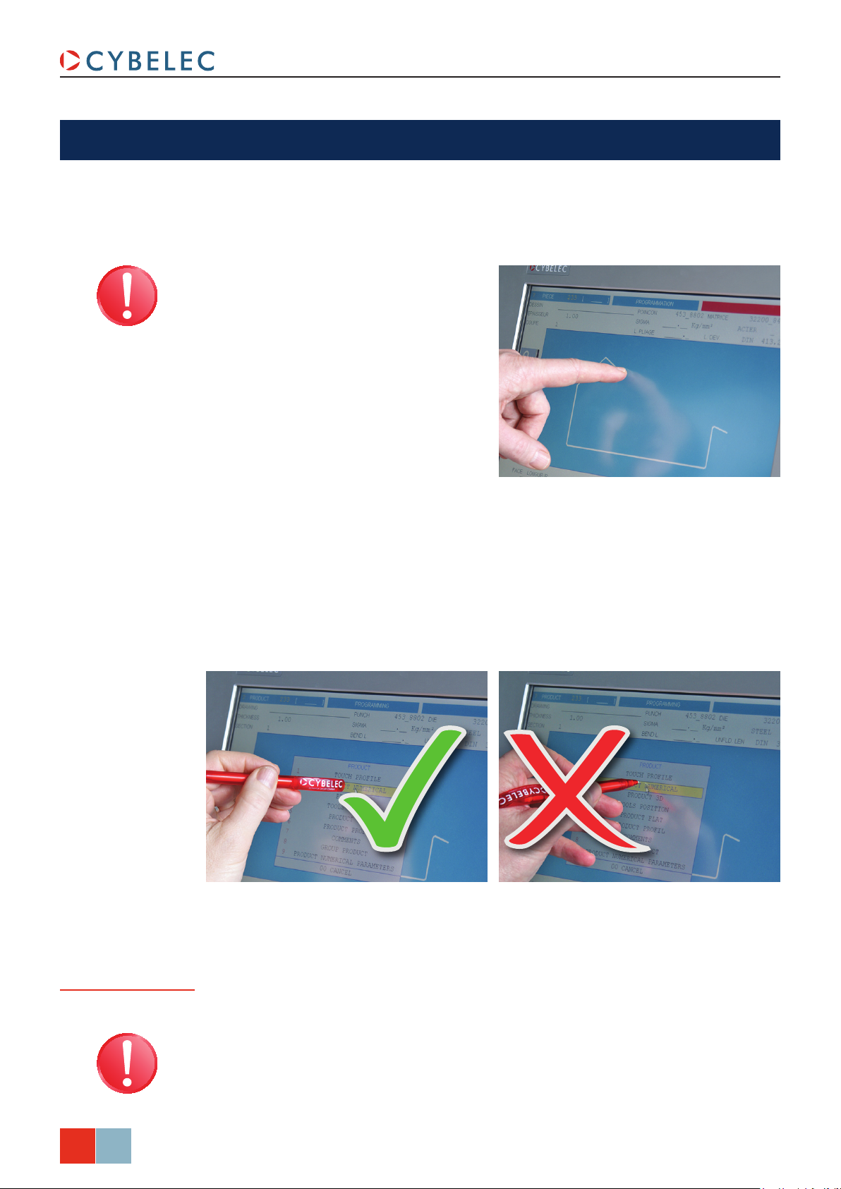
Touchscreens are pressure
sensitive.
Do not press down hard on the
screen.
Pressing hard on the screen will
damage the display. Such damage
is not covered by manufacturer
warranty!
ModEva 15T User Manual
Do not use sharp and/or pointed objects (sheet metal, screwdriver, metal pen ball, etc.) to
touch the screen; only use your fingers (with or without gloves on) or a plastic pen. Make
sure that your gloves do not have metal particles encrusted in the finger tips as they may
also damage the screen.
Take a few minutes to practice pressing gently on the screen, you will find that the screen
is very reactive and it is pleasant to use.
Screen Cleaning
Feb.
4/34
2015
V2.0
Turn off the ModEva to clean its screen. Use only a damp and smooth cloth with soap or a
neutral detergent.
NEVER use solvent, petrol, benzene, alcohols, etc.
Page 11
ModEva 15T User Manual
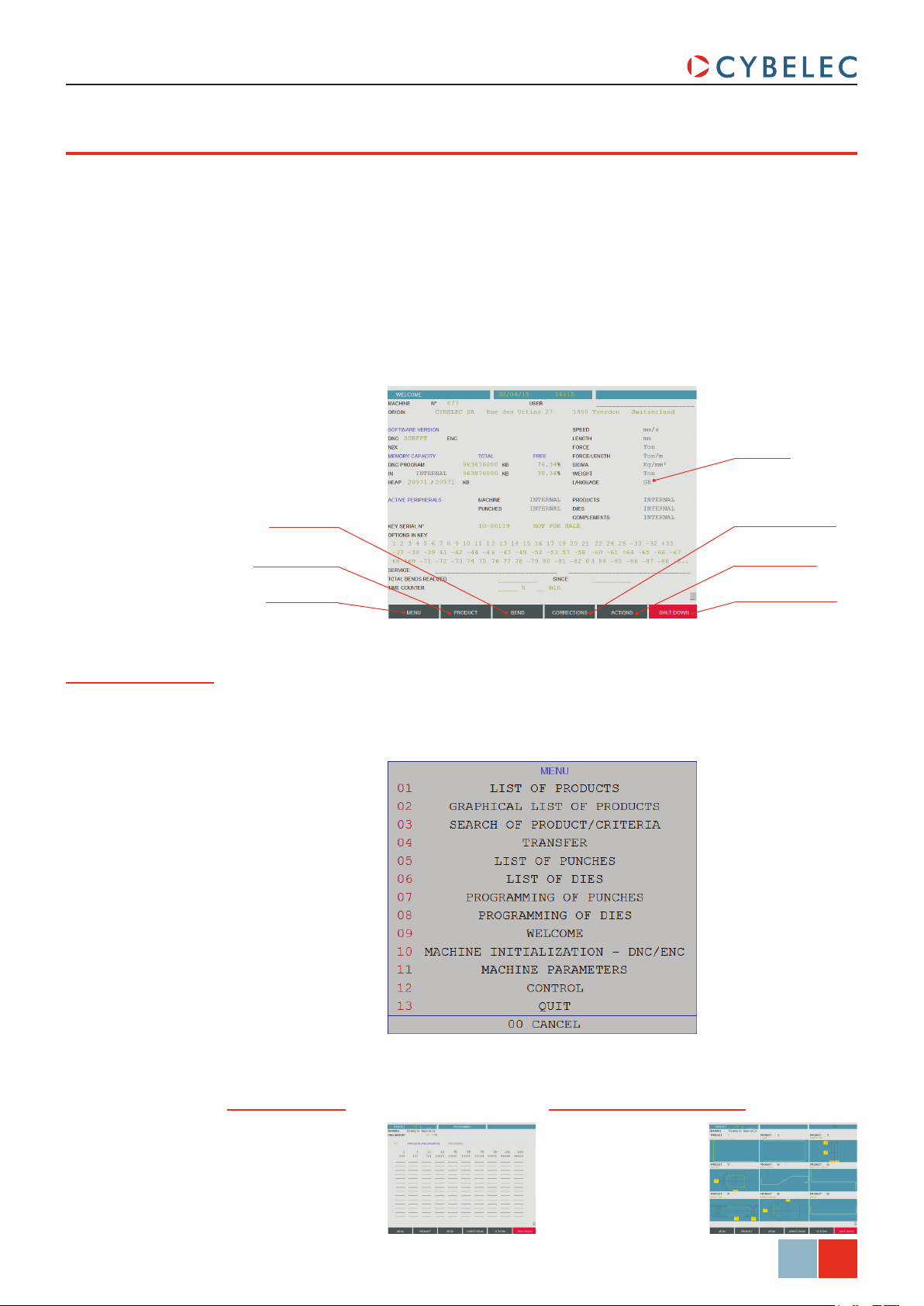
General naviGaTion
The main navigation through the many different pages of the ModEva software is done by
mean of the buttons at the bottom of the screen.
The pages contain fields of different colors:
• The blues fields are fixed texts, such as category titles or headings.
• The gray fields, when touched, open a pop-up window with a list a choices.
• The black fields are those where data is to be entered.
• The khaki fields are information data fields, like real position of axes or actual value of
a variable.
Language
Menu Button
Bend Button
Product Button
Menu Button
Correction Button
Actions Button
Shut Down Button
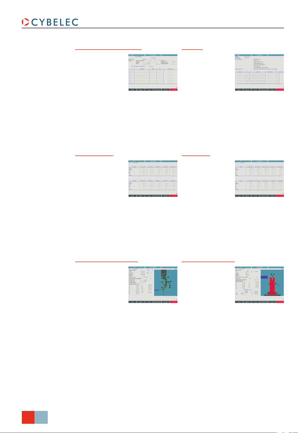
The Menu button allows you to access programming pages, whether they are related
to products, tools or general machine parameters. When touching the Menu button, the
following pop-up window is displayed.
List of Products
Graphical List of Products
Search of Product/Criteria
Transfer
List of Punches
List of Dies
Programming of Punches
Programming of Dies
Welcome
Machine Initialization DNC/ENC
Machine Parameters
List of Products Graphical List of Products
Allows extracting
products stored in
the NC, in numerical
increasing order.
Allows extracting
products stored in
the NC, in numerical
order, and with the
graphic associated
to them.
Feb.
2015
V2.0
5/34
Page 12
Search of Product/Criteria Transfer
ModEva 15T User Manual
Allows searching for
different products
stored in the
numerical control
according to certain
criteria.
List of Punches
Gives a quick
glimpse at the main
parameters of the
punches stored
in the numerical
control. From this
list, you can see the
complete description of the tool by simply
touching its name. The Programming of
Punches page is then displayed.
Allows making data
transfers from one
memory to another
(USB, network,
etc...).
List of Dies
Gives a quick
glimpse at the
main parameters
of the dies stored
in the numerical
control. From this
list, you can see the
complete description of the tool by simply
touching its name. The Programming of
Dies page is then displayed.
Programming of Punches
Programming of all
punches is done
from this page.
All the dimensions
relative to the tool
are introduced here.
A drawing representing the tool is displayed
on the right of the screen.
Programming of Dies
Programming of all
dies is done from
this page.
All the dimensions
relative to the tool
are introduced here.
A drawing representing the tool is displayed
on the right of the screen.
6/34
Feb.
2015
V2.0
Page 13

ModEva 15T User Manual
Welcome Machine Initialization DNC/ENC
Main data for the
machine and the
numerical control.
Gray color fields
are multiple choice
fields which can
be modified (see
General navigation, page 5).
This page is reserved
for the technical
maintenance of the
numerical control or
the machine.
It allows clearing the
ModEva data and to
modify the physical indexes of the machine.
The level 3 password (see Access by
Password, page 31) is necessary to
intervene on this page.
Machine Parameters Control
This page is the first
of the pages which
constitute the list of
all the parameters
which condition the
functioning of the
numerical control.
Displays eventual
messages related to
specially configured
inputs Control 1 to 8.
This data can only be modified with a
level 3 password (see Access by Password,
page 31).
This data may be modified only with the
help of competent technical support.
Feb.
2015
V2.0
7/34
Page 14

ModEva 15T User Manual
Product Button
The Product button allows you to access all the different pages necessary to create
products. When touching the Product button, the following pop-up widow is displayed.
TouchProle
Product Numerical
Product 3D
Tools Position
Comment
TouchProfile Product Numerical
Allows the operator
to create a product
by intuitively drawing
a profile directly on
the screen.
Allows the operator
to construct and
calculate a product
and to visualize the
profile in real time.
See TouchProfile
Programming, page
16 for more information.
Product 3D
Allows the operator
to create a product
in 3 dimensions. See
also 3D Program-
ming (optional), page
19.
See L-Alpha
Programming, page
18 for more information.
Tools Position
Allows defining
several work
stations. See also
Tools Position, page
12.
8/34
Feb.
2015
V2.0
Comment
Allows completing
the product data
with a series of commentaries. These
commentaries are
programmed using a
PC software.
Page 15

ModEva 15T User Manual
Bend Button
The Bend button allows you to access the different work pages, from which the created
products can be produced. When touching the Bend button, the following pop-up window
is displayed.
Bend Numerical
Bend 2D
Bend 3D
Image Bend
Bend Function
Tools Bend
Bend Numerical Bend 2D
Recapitulates all the
data for the current
sequence.
See Bend Numerical
Page (Direct Programming), page
22.
Allows simulating
the feasibility of
the product and
correcting the
bending order if
necessary.
See Bend 2D Page,
page 21.
Bend 3D Image Bend
Allows the operator
to simulate the feasibility of the product
and to correct, if
necessary, the stop
position as well as
the position of the
product relating to the tools.
This page is optional.
Allows the operator
to visualize the part
in 3D, while at the
same time getting
instruction on how
to handle the part.
Is only available if
the part was created on a CAD software
able to generate a Cybelec compatible
program with images.
Feb.
2015
V2.0
9/34
Page 16

Bend Function Tools Bend
ModEva 15T User Manual
Allows programming
any possible auxiliary functions of the
machine.
Allows modifying
the position and the
width of the tools
mounted on the
machine. Certain
safety factors can
also be modified
here.
Correction Button
The correction button allows you to access the corrections page, where the individual
bends of a part can be fine-tuned. When touching the correction button, the following
pop-up window is displayed.
Corrections
Corrections
Allows applying the
corrections to the
different machine
axes as a function of
the results obtained
during bending.
See Bending, Tests
and Corrections, page 24.
10/34
Feb.
2015
V2.0
Page 17

ModEva 15T User Manual
Actions Button
The actions button allows you to choose from a list of action available on the page where
you currently are. The content of the list changes contextually. Here below are examples
of the pop-up windows being displayed when touching the actions button.
Language
To browse through the available languages, simply touch Language field on the screen.
Available languages are:
• CH 中文.
• CZ Český.
• DE Deutsch.
• DK Dansk.
• ES Español.
• FI Suomi.
• FR Français.
• GB English.
• GR Ελληνικά.
• HU Magyar.
• IT Italiano.
• KO 한국의.
• NL Nederlands.
• PL Polski.
• PT Português.
• RU Русский.
• SE Svenska.
• SI Slovenski.
• TR Türkçe.
• TW 台灣.
The list of available languages is subject to change and may
increase over time.
Feb.
2015
V2.0
11/34
Page 18

toolS PoSition
The Tools Position page allows defining several places of work and hence allows the
operator to visualize the tools assembly.
punch adjuSTMenT
middle of the machine
ModEva 15T User Manual
→ Tools position
Punch placed in the
Punch name
Punch position
Setting inStructionS:
1. Touch the beam (it will turn blue)
to select the punch. The letter P is
displayed next to the punch name’s
selection field.
2. Touch the P field. The window to the
right is displayed.
3. Touch the desired punch. Touch it a
second time to select it, or simply
confirM.
touch
4. Enter the tools desired position in the
field.
Introducing a value equal to the half
of the beam’s width minus the half of
the tool length will place the tool in the
center of the machine (in our example:
3500/2 – 195/2 = 1652.5 mm).
Punch length
12/34
Feb.
2015
V2.0
5. Modify the L field by introducing
the value (here 195.00) which
corresponds to the required tool
length. In the front view the selected
tool appears in dark blue.
Page 19

ModEva 15T User Manual
die adjuSTMenT
Proceed in the same manner as for Punch Adjustment.
→ Tools position
Die placed in the middle
of the machine
Die name
Die position
Die length
Setting inStructionS:
1. Touch the table (it will turn blue) to
select the die. The letter D is displayed
next to the die name’s selection field.
2. Touch the D field. The window to the
right is displayed.
3. Touch the desired die. Touch it a
second time to select it, or simply
confirM.
touch
4. Enter the tools desired position in the
field.
Introducing a value equal to the half
of the table’s width minus the half of
the tool length will place the tool in the
center of the machine (in our example:
3500/2 – 195/2 = 1652.5 mm).
5. Modify the L field by introducing
the value (here 195.00) which
corresponds to the required tool
length. In the front view the selected
tool appears in dark blue.
Feb.
2015
V2.0
13/34
Page 20

addinG workinG STaTionS
Most parts require different sets of tools to be bent. It is therefore possible to define
several working stations in the tooLs Position page.
Double horned punch Right horned punch
ModEva 15T User Manual
→ Tools position
Inverted tool
Horned punch
Setting inStructionS:
1. Once the first working station is defined, a touch on either the beam or the table will
allow adding another tool.
2. The procedure to select, define and position the tool is the same as the one
explained before (see Punch Adjustment, page 12 and Die Adjustment, page
13).
14/34
Feb.
2015
V2.0
Page 21

ModEva 15T User Manual
CreatinG a Part ProGraM
This chapter describes, by means of a concrete example, diverse ways of using your
ModEva.: with the TouchProfile Programming, with the L-Alpha Programming (see
page 18), with the Bend Numerical Page (Direct Programming) (see page 22) and with
the 3D Programming (optional) (see page 19).
We assume in this part that all the necessary tools have already been
programmed as well as the machine parameters.
The product being used as an example is composed of 2 sections (profiles), but the
procedure is identical for one or several sections.
30.0
Section 1
45.0
40.0
150.0
200.0
Section 2
20.0
45°
The side flaps with the oblong holes, which are included in section 1, will be made first,
so that a punch of identical length as that for section 2 can be used.
We presume that the operator knows how to reach level 1. Should this not be
the case, see chapter Protection of the Access Levels, page 29.
These procedures indicate to the operator a programming method
recommended by CYBELEC, enabling to assimilate by the example the
functioning of the software.
For additional information, please consult the 2D Reference Manual and/or the
3D Reference Manual, which each contains a table of contents and a detailed index
facilitating the search for information.
Feb.
15/34
2015
V2.0
Page 22

Touchprofile proGraMMinG
Product number
Material thickness
ModEva 15T User Manual
→ TouchProfile
Tools selection
Material
Material Sigma
Zoom buttons
Delete selected segment
Selected bend data
Bending length
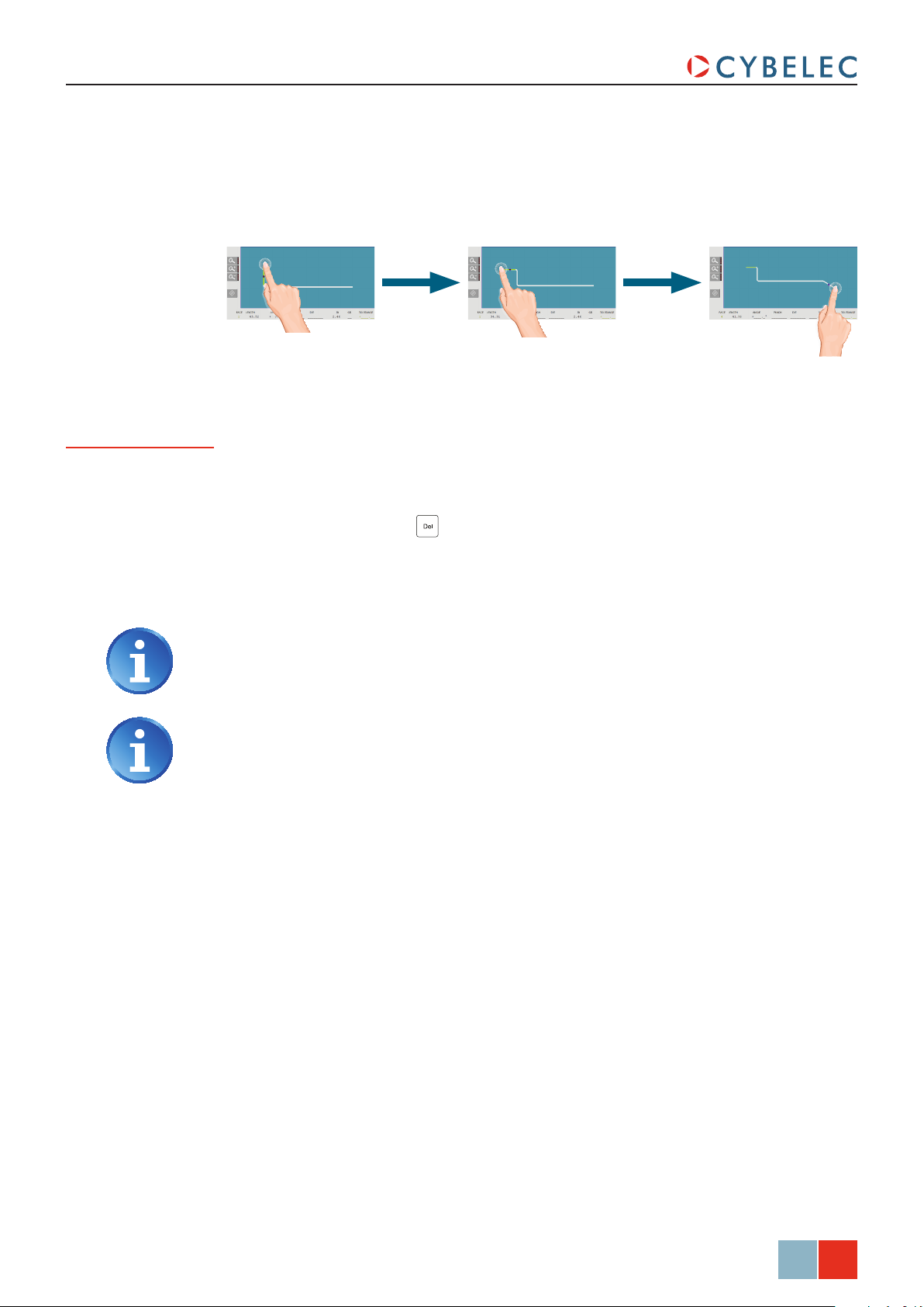
In this mode, the operator can very intuitively draw a profile directly on the screen.
Setting inStructionS:
1. Touch the button and select New product in the list.
2. First select the material, enter its thickness and Sigma, enter the bending length, and
select the tools to be used for the part by touching their respective fields.
Selecting tools directly from the TouchProfile page places them automatically
in the middle of the machine. To change their position, see Tools Position, page
12.
16/34
Feb.
2015
V2.0
3. Draw the profile of section 1 (see
Creating a Part Program, page 15) by
touching the screen where you want
to add a segment.
4. Touch on the middle of a segment
or on an angle to modify its value.
A purple dot indicates the selected
segment, and its value is highlighted in
the bend information line.
Touching this icon allows erasing
the selected segment.
5. Proceed in the same manner to adjust
all segments and angles.
Page 23
ModEva 15T User Manual
6. Touch the SECTION field, enter the value of 2 and leave the field. This automatically
initializes a new page for programming section 2.
7. Draw the profile of section 2 (see Creating a Part Program, page 15) by touching
the screen where you want to add a segment.
8. Proceed in the same manner as for section 1 to adjust lengths and angles values.
Special functions for a bend
9. If a bend needs special parameters (large radius, special tool), it can all be
programmed on the bend data line of the corresponding sequence.
• Activate a special tool by touching the corresponding field, and select it from a list
(deactivate with the
• Change the value of the radius (Ri field) and define how many steps the NC will
make to execute it (CR field).
button).
Programming 99 in the CR field will automatically calculate the maximum
possible step bends. The resulting value may be reduced. However, if it is
increased over the maximum calculated value, the resulting radius and angle
will be drastically affected.
A special punch or /and die means there must be an additional working station.
10. Once all the segments and angles adjusted, go to the Bend 2D Page (see
page 21).
Feb.
2015
V2.0
17/34
Page 24

l-alpha proGraMMinG
In this mode, the operator can define each step (length and angle) of a profile in a table.
In the bottom section of the page, the operator can see the profile being automatically
drawn as a function of the introduced data. The value of the internal radius is
automatically calculated as a function of the selected tools.
ModEva 15T User Manual
→ Product Numerical
Tools selectionMaterial Sigma
Product number
Material thickness
Bend data table
Graphic representation
of the prole
Material
Bending length
When introducing data in L-Alpha mode, simply begin from one of the
extremities of the profile and fill in the values of each face and angle one after
another, with the last face having no corresponding angle.
Setting inStructionS:
1. Touch the button and select New product in the list.
2. First select the material, enter its thickness and Sigma, enter the bending length, and
select the tools to be used for the part by touching their respective fields.
18/34
Feb.
2015
V2.0
Selecting tools directly from the L-Alpha page places them automatically in the
middle of the machine. To change their position, see Tools Position, page 12.
3. Touch the first field of the
corresponds to the first length.
4. Touch the first field of the
corresponds to the first angle to be bent.
5. Proceed in the same manner for all steps and angles of the profile of section 1 (see
Creating a Part Program, page 15).
6. Touch the
section field, enter the value of 2 and leave the field. This automatically
initializes a new page for programming section 2.
7. Proceed in the same manner as for section 1 to define lengths and angles values.
8. If a bend needs special functions, see Special functions for a bend, page 17.
9. Once all the segments and angles defines, go to the Bend 2D Page (see page 21).
Length column and introduce the value of 45.00 which
angLe column and introduce the value of 90° which
Page 25

ModEva 15T User Manual
3d proGraMMinG (opTional)
In this mode (available only on the ModEva software with 3D option), the operator can
conceive a part directly in 3 dimensions. The definitions of the different icons you will
encounter through these pages are described in the 3D Reference Manual, in chapter
Definition of the Icons.
→ Product 3D
Product data eld
Tool window
(here showing add
rectangular face)
Working window
(here showing
two-dimensional view)
Display window
(here showing
axonometric view)
Touching the display window inverts the two-dimensional and the axonometric
views, allowing the operator to create his part in two or three dimensions.
Setting inStructionS:
1. Touch the button and select new Product in the list.
2. Touch the
Product data field and select the material, enter its thickness and Sigma,
enter the bending length, and select the tools to be used for the part by touching
their respective fields.
Selecting tools directly from this window places them automatically in the
middle of the machine. To change their position, see Tools Position, page 12.
3. Touch Quit to confirm the chosen values.
4. Touch the
button and select Modify 1f or Modify 2f. The difference
between the two functions is:
Modify 1f: Shows the product in plan mode (2D).
•
Modify 2f: Shows the product in plan mode and in axonometric mode (3D).
•
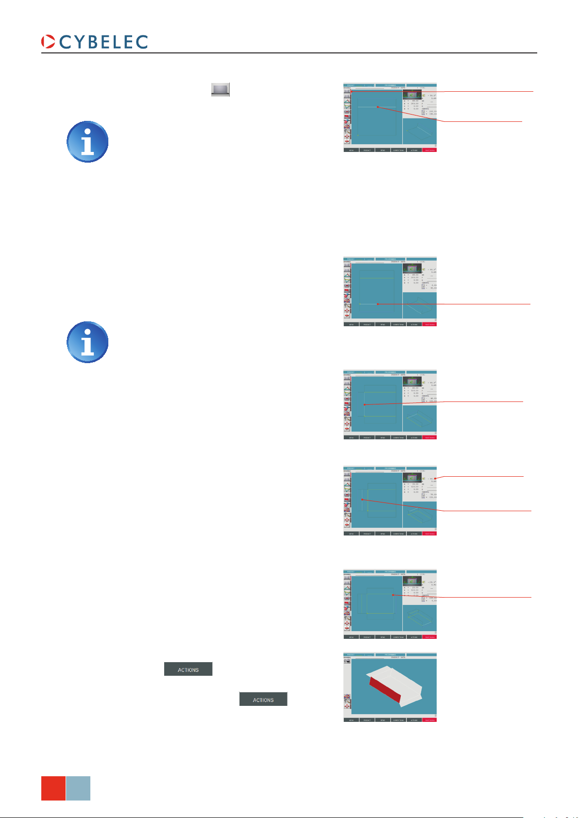
5. Touch this button to add a
rectangular face. The base rectangle
Base rectangle
dimensions
appears in plan mode in the work
window as well as in axonometric
mode. The tool window is adapted.
6. Introduce the dimensions for A and B
(in our example: 150.00 and 200.00).
Feb.
2015
V2.0
19/34
Page 26
ModEva 15T User Manual
7. Touch this button again to add a
rectangular face.
The red rectangle to the right of the
icons lights up and indicates that the
function is active.
8. Touch the segment of the outline to
which the side is to be added.
9. In the tool window, adjust the height
of the side (field A, here 45.00). The
angle value is 90° by default. The
internal radius is already calculated.
10. Add a second side. The same function
still being active, simply touch on the
lower segment where the side is to be
added.
The value A has been memorized and
is automatically attributed to the new
side.
Function active indicator
Touching this segment
will attach the new face
here
Touching this segment to
add the second side here
11. Add a third side. Touch the left
segment where the side is to be added
(the function remains active until
deactivated).
12. Enter 40.00 in the A field in place of
the previous memorized value (45.00).
13. Add a fourth side by touching the
left segment where the side is to be
added.
14. Enter 30.00 in the A field in place of
the previous memorized value (40.00),
and change the direction of the side by
entering -90.0° for the angle value.
15. Add the last side by touching the right
segment.
16. Change field A value to 20.00, and
angle value to -135.0°.
Touching this segment to
add the third side here
Enter a negative angle
value
Touching this segment to
add the fourth side here
Touching this segment to
add the last side here
20/34
Feb.
2015
V2.0
17. To check the construction, touch the
button and select VisuaLize.
18. To come back to the construction
mode, touch the
button
and select Modify 1f or Modify 2f.
19. The product is now finished, go to the
Bend 2D Page (see page 21).
Page 27

ModEva 15T User Manual
bend 2d paGe
→ Bend 2D
Setting inStructionS:
1. At this point, a product must have been programmed, using one of the modes
previously explained.
2. In the
3. Touch the
4. The message
5. The succession of sequences can then be visualized using the
siMuLat. field, choose the option without Progr. Bends.
button and select search Bending range in the list.
siMuLating runs…, then caLcuLating... appears in the interactive field
on the top right-hand corner of the screen.
and keys.
The operator has the possibility to modify the bending range (see the
corresponding chapter in the 2D Reference Manual) or to ask the software to
respect specific criteria like minimum of swings or returns. For that, please refer
to the 2D Reference Manual, section Simulation criteria.
In case where the software program does not find any solution, the bending
range must be imposed manually. See Bending order in the 2D Reference Manual.
Feb.
2015
V2.0
21/34
Page 28
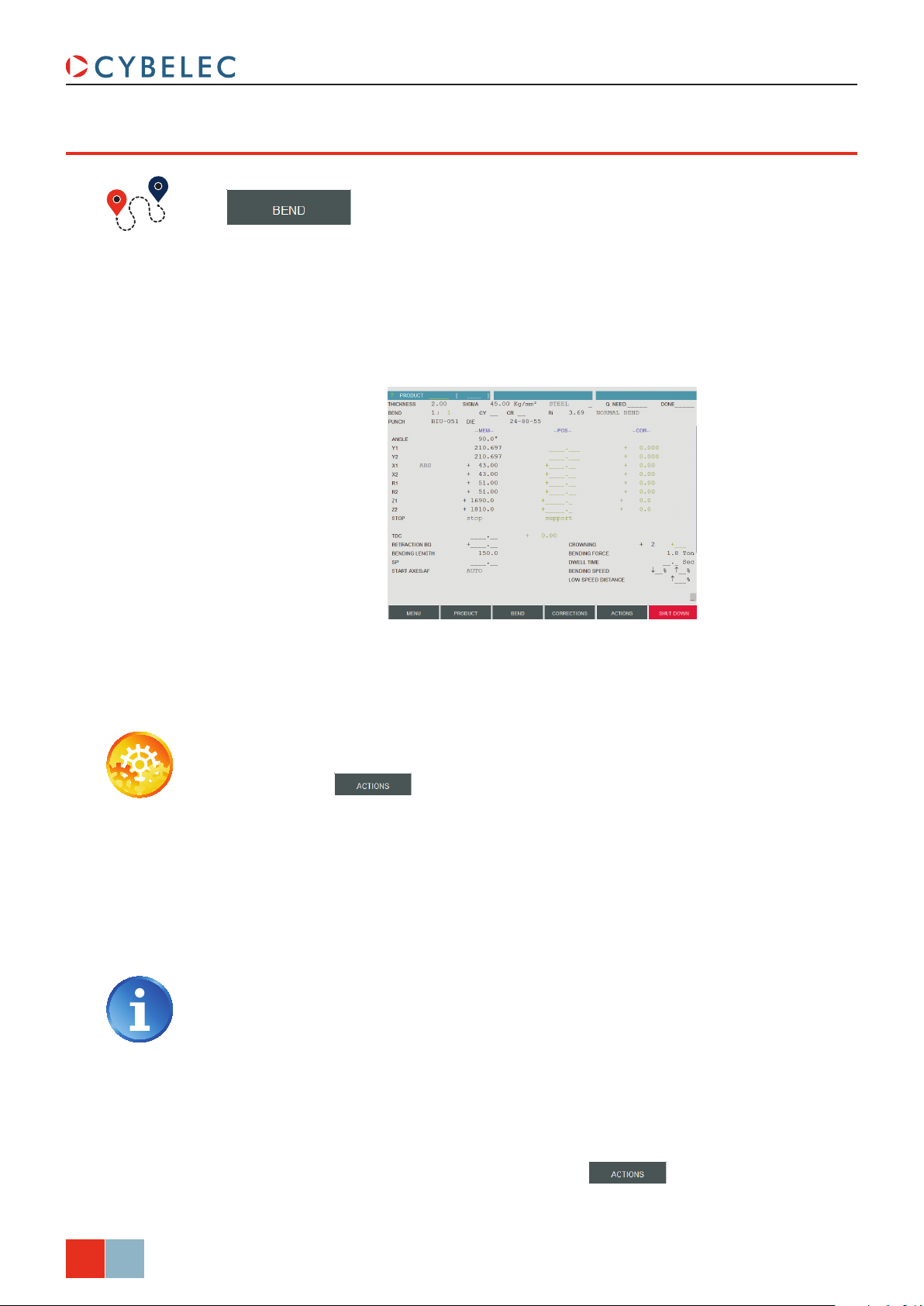
bend nuMerical paGe (direcT proGraMMinG)
→ Bend Numerical
This type of programming is often used for simple products or by operators having
worked on conventional press brakes without numerical controls.
This page is very user-friendly, for the operator has on one single screen all the
information and fields necessary for the programming of his product.
ModEva 15T User Manual
The bending order is chosen by the operator, since he programs directly each bend.
In this example, we will program the part described in Creating a Part Program (see
page 15).
Setting inStructionS:
1. Touch the button and select new Product in the list.
2. On the top of the screen, select the material, enter its thickness and Sigma, and
select the tools to be used for the part by touching their respective fields.
3. Program the required
the tools and the material already programmed. It is also possible to directly enter
the Y1 / Y2 values without programming the angle.
4. Program the real position of the back gauge X1 (here 43.00). X2 can be individually
modified if different from X1.
angLe (here 90.0°). The Y depth will be calculated according to
The programming of the real position of the back gauge requires of the operator
to subtract (approximately) the steel thickness from the external dimension of
the product.
5. If necessary, program the specific data for the current sequence (see Position of axes
and other functions, page 23)
6. The two bends of section 1 (see Creating a Part Program, page 15) being identical,
enter 2 in the CY field (CY stands for cycle, meaning this sequence is repeated twice
in the program).
22/34
Feb.
2015
V2.0
7. To create the subsequent sequence, press the
Bend in the list. It can be seen that all the data has been copied into the second
sequence.
button and select coPy
Page 29
ModEva 15T User Manual
There is another way to program on this page, which has however some
limitations depending on the product and the chosen bending order. It consists
of entering the external flange dimension in the X field of the back gauge, and
then programming a constant negative correction (see Bending, Tests and
Corrections, page 24) corresponding to (approximately, according to your
experience with the tools and the material) the material thickness.
8. Proceed in the same manner as for section 1 to define lengths and angles values.
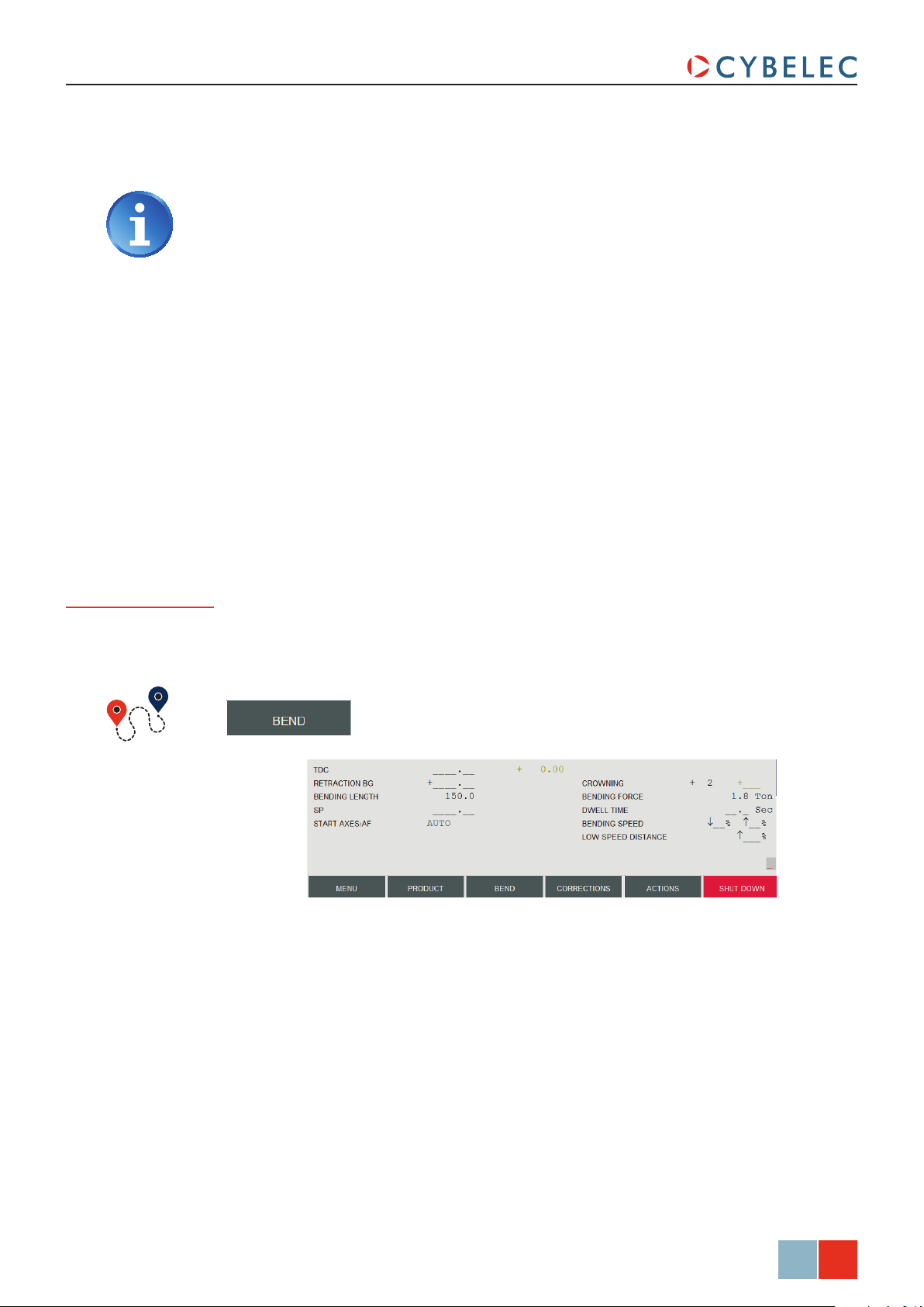
Position of axes and other functions
The bottom section of the Bend Numerical page contains all the extra parameters for a
bend. Some, like the bending force, are calculated automatically. But all these values can
be modified by the operator.
→ Bend Numerical
According to his needs, the operator can modify the following items:
• TDC, for Top Dead Center. If not programmed, the beam will rise to the maximum
TDC.
retraction Bg, for the back gauge retraction.
•
Bending Length, defines the length of the part being bent, this parameter must already
•
have been defined during the part programming phase.
• SP, for Switch Point. The point where the beam switches from High Speed to Bending
Speed.
start axes/af, setting this parameter to externaL gives manual control over the back
•
gauge movement. This means the operator must personally give the start to the back
gauge movement, using for example the foot switch or the start button.
crowning, if available, is automatically calculated.
•
dweLL tiMe, defines the amount of time during which the pressure is maintained.
•
Feb.
23/34
2015
V2.0
Page 30
•
Bending sPeed, defines the downward bending speed and the upward moving speed
from BDC to Pinch Point point.
Low sPeed distance, defines the portion (expressed in %) of the upward movement
•
between the TDC and the Pinch Point which will be carried out at low speed; the
continuation of the upward movement is made at high speed.
Complementary explications are found in the 2D Reference Manual.
bendinG, TeSTS and correcTionS
This chapter explains how to proceed in order to execute a product. This way of doing is
destined only to demonstrate how to use the numerical control.
ModEva 15T User Manual
The testing and adjusting operations can be carried out in the order decided by the
operator.
Setting inStructionS:
1. Go into semi-automatic mode .
2. If necessary, move to the first sequence by means of the
3. Press the start key
4. Carry out the bend with a trial product.
5. Measure the flap and the obtained angle.
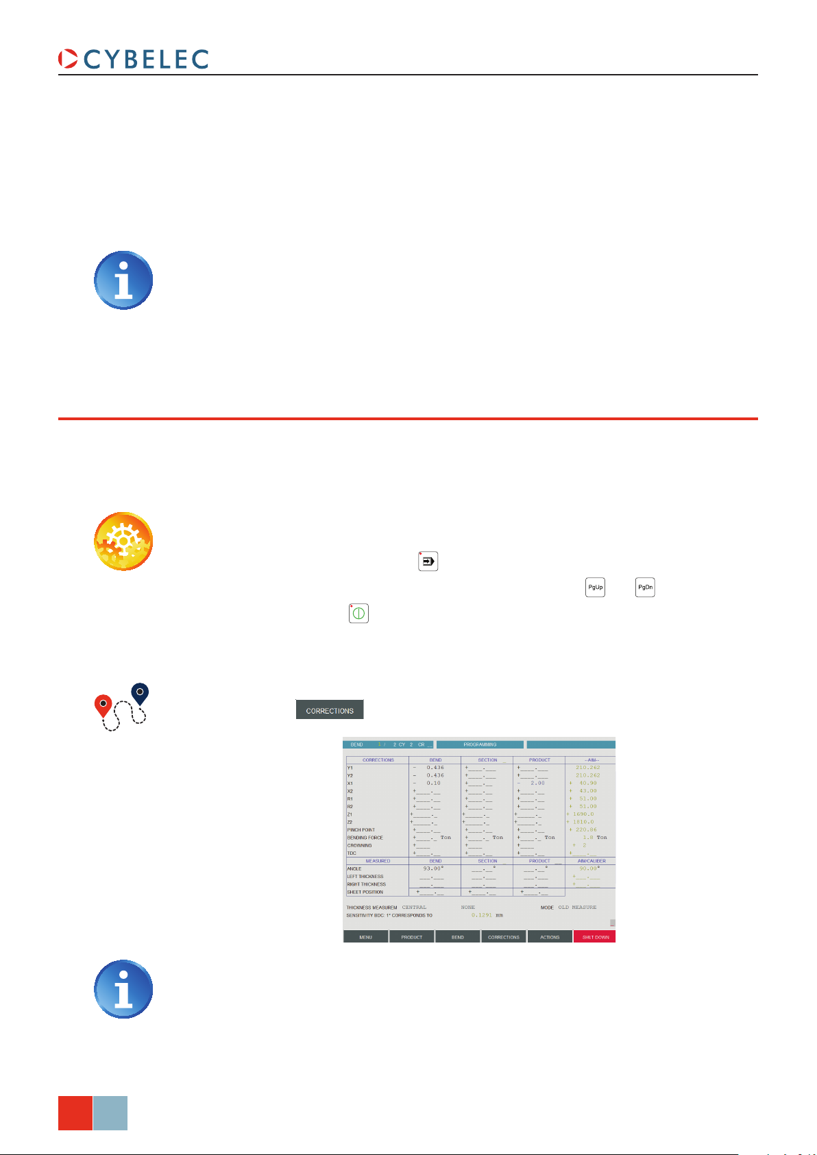
6. Touch the
in order to position the axes on the first sequence.
button and select corrections in the list.
and keys.
24/34
Feb.
2015
V2.0
In the screen above, the correction of -2.00 mm corresponds to the material
thickness when programming section 2 in Bend Numerical Page (Direct
Programming), page 22.
7. If necessary, correct the flap (in this example, a correction of X = - 0.10 is assumed)
for the current bend.
Page 31

ModEva 15T User Manual
See also the Corrections section in the 2D Reference Manual.
Depending on the material, the machine adjustment and the exactness of the
data introduced, 2 or 3 corrections can be necessary for a bend. This can be
considered as being a normal situation.
10. Proceed in the same manner for all the bends by navigating through the bends by
8. Touch the angLe field, Bend column, and enter the measured angle (93.0 in this
case). The software automatically calculates the necessary correction (-0.436, which
can be seen in the Y1, Y2 fields, in the Bend column).
9. Carry out a second test bend (on the same sequence, with a second test product). If
necessary, make a new correction.
means of the
and keys.
11. When all the bends of the product turn out as expected, go into automatic mode
and choose the work page you like:
• Bend Numerical (see page 9),
• Bend 2D Page (see page 21),
• Bend 3D (see page 9) for 3D software.
Feb.
2015
V2.0
25/34
Page 32

MeMorize or SearCh a ProGraM
MeMorize a proGraM
The memorizing of a product can be carried out from all pages containing the Product
field at the top of the screen.
Setting inStructionS:
1. Set the ModEva in programming mode .
ModEva 15T User Manual
From the List of Product page
2. Enter a number in the
3. Touch the
4. If the message
Select:
canceL to choose another number,
•
confirM to overwrite the existing product.
• or
exists appears, it indicates that the number selected is already in use.
Product field.
button and select MeMorize Product in the list.
Selecting MeMorize Product in fiLe allows giving the product an alphanumerical
name, and also select its location.
If you wish to do this memorizing by having a global view of the existing products, it can
be done from the List of Product page.
→ List of products
Select where the le will
be saved here
Insert a description
of the part here
26/34
Feb.
2015
V2.0
Setting inStructionS:
1. In the drawing field, introduce a reference, if needed.
2. If you want to memorize the product elsewhere than in the internal memory, touch
Products and grouPs in field and make your choice.
the
3. Touch the
4. Touch the
5. The message
the screen.
6. The number of the product recorded will then appear in the list.
Product field and introduce the storage number (1 to 89.999).
button and select MeMorize in the list.
saVing... appears in the interactive field on the top right-hand corner of
Page 33

ModEva 15T User Manual
Search a producT
Standard Method
If you know the number of the product (provided that it is in the active peripheral), you
can search for it from all pages displaying the Product field on the top left corner of the
screen.
To this end:
1. Introduce the product number in the
2. Touch the
button and select search Product in the list.
Product field.
If you don’t know the product number, you can search for it in the list of products’ page.
Rapid method
1. Touch the button and select List of Products in the list.
2. If you want to search for the product in a location other than the internal memory,
touch the
3. Simply touch the desired product and press the
4. The product is now in the work memory (its number is displayed in the
Products and grouPs in field and make your choice.
key.
Product field).
From any page displaying the Product field:
1. Touch the
Product field and press the key.
2. The following window is displayed:
Use these arrows to
browse through the
available products
3. The products are initially listed in increasing order by product number.
4. Touch the product you want and select
confirM to load it.
Touching the product twice will also open it.
Feb.
2015
V2.0
27/34
Page 34

ModEva 15T User Manual
Sorting Products
Each column can be listed in an increasing or decreasing order by simply touching its title.
The red arrow (▲ or
▼) indicates the sorting
direction
Searching a product
Touch the table in the desired column and enter there the product number, the drawing
name or the searched date.
Graphic Method
The search criteria you
enter are displayed here
Your entry is displayed on the last line (in white), and the cursor positions itself on the first
line of the table. The names are sorted in increasing order, the first corresponding to your
entry being on the first line.
Procedure:
1. Touch the
2. Use the
and keys to scroll the list of graphical products.
3. Simply touch the desired product and press the
4. The product is now in the work memory (its number is displayed in the
button and select graPhicaL List of Products in the list.
key.
Product field).
28/34
Feb.
2015
V2.0
Touch the product number
and press to select it
Page 35
ModEva 15T User Manual
ProteCtion of the aCCeSS levelS
General inforMaTion
In this manual we will always speak of a (virtual) key position like e.g.: «Key in position 3».
Levels
Access
There are 4 access levels, 0 to 3.
0 = Programming prohibited.
1 = Creation, correction, modification, saving, deleting, transfer of one (or more)
product(s).
2 = Creation, correction, modification, saving, deleting, transfer of the tools.
3 = Programming, modification and transfer of the machine parameters.
These levels are reached by pressing the
The key position is displayed as a small pictograph at the right bottom of the screen.
When passing to non-authorized level, a password modification will be requested.
When the password has been introduced, you can «navigate» in the levels inferior and
equal to the authorized one without reintroducing the password.
+ , + , + or + keys.
Release the numerical key before the Alt key. Switching to level 0 reinitializes
the password request.
Password
Characteristics
Loss of the password
Certain users can modify their own password. For the others, the password can only be
changed by a user having a superior access.
The password can be composed of alphanumerical characters if such a keyboard is
available and if not only of numerical characters.
In case of loss of the password, a user with a superior level has to reprogram it.
Feb.
2015
V2.0
29/34
Page 36

uSerS
ModEva 15T User Manual
A number of different users is predefined. A predefined user is just a role and not
a physical person in particular. It can be for example all the operators having the
authorization to work on the machine.
Each predefined user possesses its own password and a maximum level which he can
reach.
level
PerSonal
PaSSword
ChanGinG of
defi ned uSe rS
naM eS of Pre-
ChanGinG of th e
1 EUL1 NO NO 1 111 Operators having level 1 access authorization
2 EUL2 NO NO 2 222 Operators having level 2 access authorization
3 EUL3 NO NO 3 333 Operators having level 3 access authorization
4 WSSUPER OK OK 3 817 Workshop supervisor
5 MACHMAN NO OK 3 Machine manufacturer's Service technicians
6 MACHMAN0 OK OK 3
SubordinateS
PaSSwordS of the
key
Pa SSword
by default
level v irtua l
uSer Generally attributed to
Responsible of the technicians at the machine
manufacturer's
After installing the machine, it is advised to modify the level 4 (WSSUPER =
Workshop supervisor) and level 3 (EUL3 = Operators with authorization level 3)
default passwords, because they are in this manual.
30/34
Feb.
2015
V2.0
Page 37

ModEva 15T User Manual
acceSS by paSSword
At the software’s startup, the virtual key is always positioned at 0.
When the operator selects one of the combinations
following message appears:
+ , + or + , the
Or 1 or 2 according to the
keys combination
Setting inStructionS:
1. Enter the password.
2. Press
3. The authorized level is shown in a box at the bottom right of the screen.
.
If the password is not correct, the message wrong Password is displayed,
indicating that the user is not authorized.
Once the authorization granted, the level remains accessible as long as another
password is not entered. Cybelec recommends accessing level 0 after your
intervention, in order to avoid making undesired changes by inadvertence.
acceSS To levelS Superior To 3
Certain users can access levels superior to 3, which enables them, among other things,
to modify the passwords. To do that, one must press the combination
following message appears:
Setting inStructionS:
1. Touch the user field and select the desired user level (see Users, page 30).
2. Touch the
and validate with the
Password field, enter the password corresponding to the requested level
+ . The
Touch here to select the
desired user level
.
Feb.
2015
V2.0
31/34
Page 38
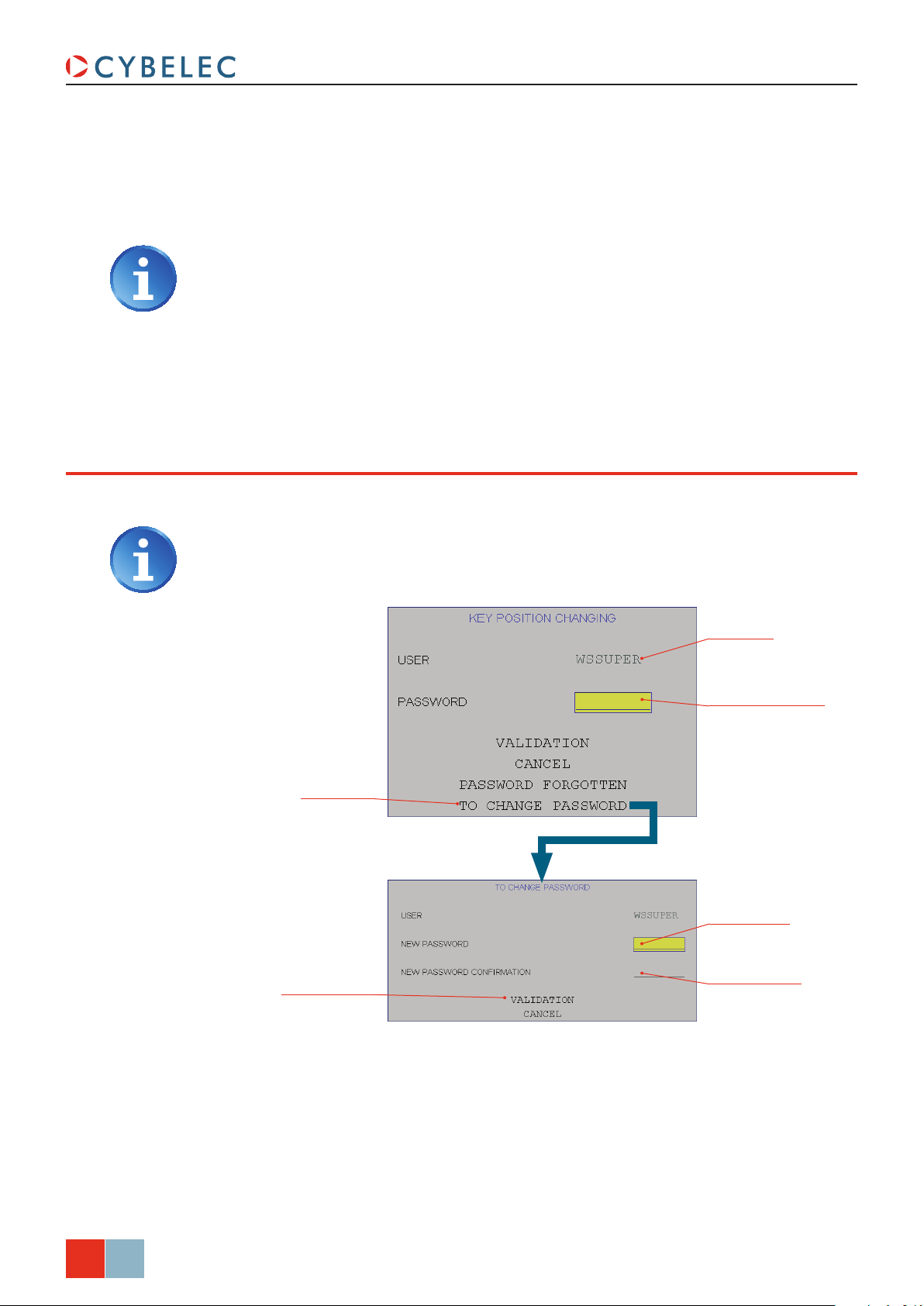
chanGe paSSwordS
ModEva 15T User Manual
3. The ModEva switches to level 3. The operator can «navigate» between levels 1 and 3
without reintroducing his password.
4. If his access level enables him, he can call the procedure to Change Passwords.
At the end of the intervention, don’t forget to pass to level 0 in order to leave the
current level.
It is possible to modify the passwords attributed by default. Certain users can do it for
themselves, others not.
In order to know the authorizations, see the table in Users, page 30.
Log in as at least
WSSUPER
Enter corresponding
password here
Touch here to change
the password
Enter the new
password here
Validate the modication
by touching here
Conrm the new
password here
32/34
Feb.
2015
V2.0
Page 39

ModEva 15T User Manual
forGoTTen paSSwordS
If a user has lost / forgotten his password, he can, if he is authorized, change it himself
(see Change Passwords, page 32).
If he is not authorized to change his password himself, he can either:
• Ask a higher user to modify the password (see Change Passwords), or
• Use the method described below, after pressing the combination
+ .
In order to know the authorizations, see the table in Users, page 30.
Choose the user whose
password is forgotten
Touch here to recover
the password
Write the heLP code
down
Contact your provider with the heLP code in order to recover the lost password.
Feb.
2015
V2.0
33/34
Page 40
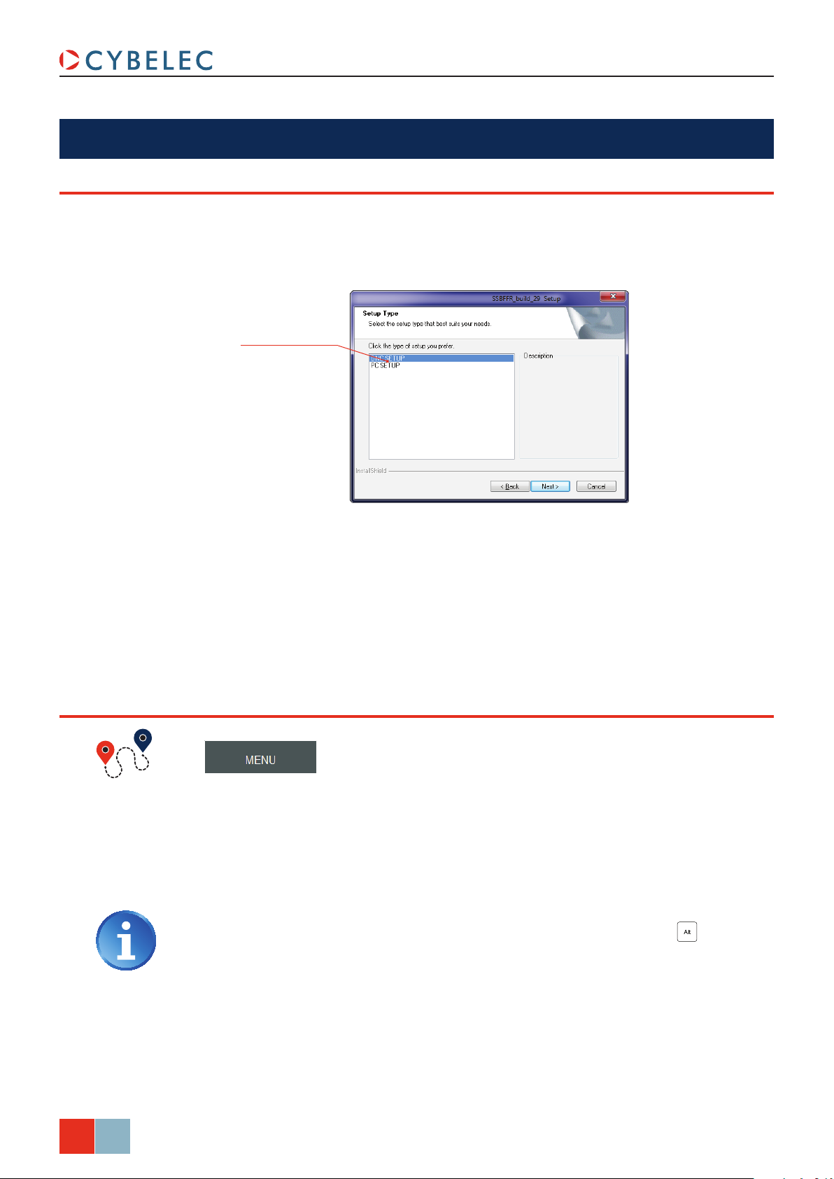
CybeleC Software
inSTallinG The SofTware
The software delivered with the ModEva can be installed on the numerical control itself of
course, but also on a PC. When running the software’s installation program, the choice is
given in a window as shown below.
Select here the type of
installation desired
ModEva 15T User Manual
leavinG The SofTware
It is possible at any time to quit the task after having memorized the current state.
However it is important to leave the software in the correct way by using the
function.
This procedure will close the PC-ModEva software and bring you to the Windows
environment.
The same procedure can be used on the PC software, or press the + Menu
keys on any page.
→ Quit → Confirm
Quit
34/34
Feb.
2015
V2.0
 Loading...