

Page 1
/
PS
Version for synchronized press-brakes.
encoder.
ModEva CNC /C
ModEva CNC version "C" (Compact): can control up to 4/6 axes or even 18 with CAN axes*.
ModEva CNC /M
ModEva CNC version "M" (Medium): controls up to 12/14 axes or even 18 with CAN axes*.
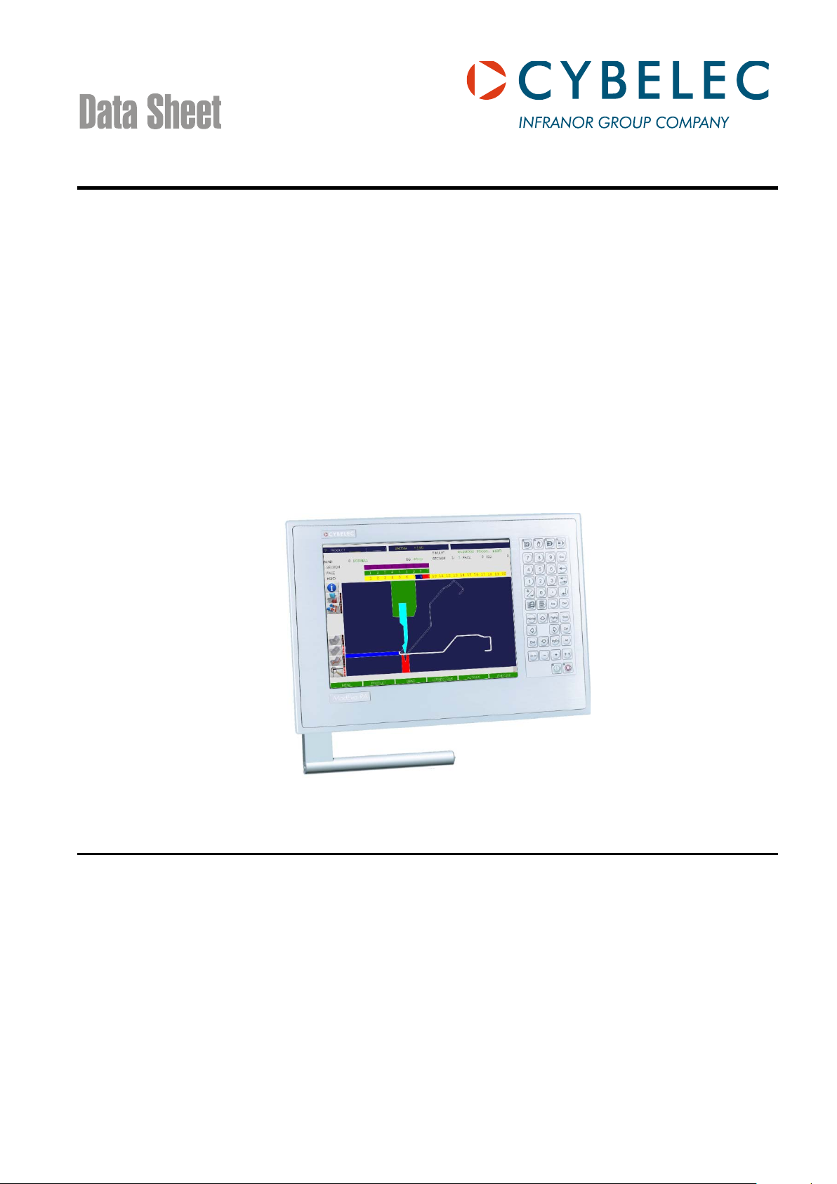
ModEva™ 15T
ModEva is a range of numerical control units intended specifically for sheet metal working.
Depending on the software installed, ModEva can be used on synchronized or non-synchronized press-brakes of the upstroking or down-stroking type.
ModEva numerical control units can control up to 18 axes of which 2 are synchronized hydraulic axes especially intended for
press-brakes.
The numerical control is composed of 2 main elements:
• The programming console.
• The CNC (Computerized Numerical Control).
The programming console is located within the operator's reach, generally fixed to a swiveling arm; the CNC is placed inside
the electric cabinet.
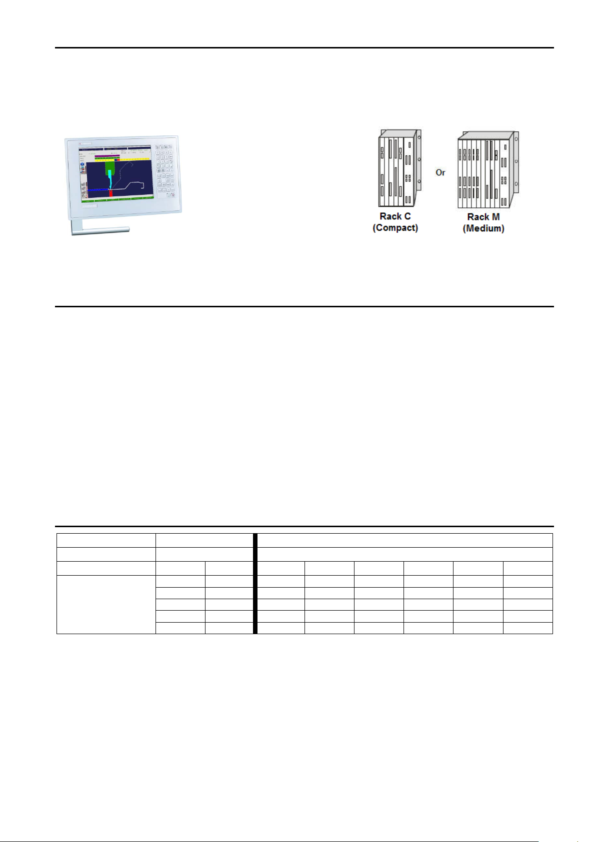
The CNC is available in 2 rack formats.
• Rack version C (Compact): This is a small, very compact rack, convenient for many situations.
• Rack version M (Medium): This is a bigger rack permitting a varied combination of configurations.
The software enables manufacturers to configure the axes, the inputs/outputs and the auxiliary functions according to their
needs.
Versions
PC
* see definitions of the axes and configurations further on in the document.
CDS_ModEva_15T_EN_V2.5.docx5 Aug 2014 1
Like the PS but for press-brakes with mechanical (or hydraulic) stops and beam control with a linear
Page 2
ModEva Range
CNC / C (Compact)
CNC / M (Medium)
2
5
Axis position (slot No)
0 1 0 1 2 3 4
5
NMX
NSX
NMX
NSX
NSX
NSX
NMX
NLR
NMX
NSX
NSX
NLR
NCX
-
NMX
NSX
NSX
NLR
NMX
ModEva is a modular range with a choice of:
• 1 programming console 15” touchscreen.
• 2 programs (2D or 3D) an d 1 Windows XP emb. operational system.
• 2 different rack sizes depending on the number of axes and the desired technology (analog or CAN).
Definitions:
Hydraulic axes: An analog axis especially intended for controlling the beams (Y1-Y2). These two axes are on the
NPU.
Analogical axes: Axes for which position is given by an incremental sensor and instructions are provided by the CNC
via a ±10V DC analog voltage. One also corresponds to an analog interface axis. These axes are
controlled by boards called NMX / NSX. Each of these boards controls 2 axes.
CAN axes: Axes for which positioning information is handled through a CAN bus.
These axes require an NCX board on the CNC side and a CAN interface on the servo-amplifier side.
An NCX board can control up to 8 axes. The number of CAN axes is controlled as an option.
The ModEva CNC can be equipped with a maximum of 2 NCX axis boards.
NMX: A master board for 2 analog ax es. A master board controls up to 3 NSX slave boards.
NSX: A slave board for 2 analog axes. A slave board in all case s requires an NMX board.
NCX: CAN board for a maximum of 8 CAN ax es. This board can handle various protocols according to the
type of servo-amplifier used. It is possible to combine CAN and analog axes.
Configurations of CNC axes
Rack version
No. of axis boards
NMX - NMX NSX NSX
The most common
configurations
NCX NLR NCX NLR NMX NSX
CDS_ModEva_15T_EN_V2.5.docx5 Modification rights reserved 2/6
Page 3

Configuration of the consoles
TFT screen
15"
Touchscreen
Yes
Resolution
1024 x 768
Ext. keyboard socket
Yes, PS2
Ext. mouse socket
Yes, serial mouse with mini DIN socket
Power
Through the panel link
Seal
IP 54
2 cables RJ 45 twisted pair category 6. Cables 5 m or 10 m.
Dist. > 10 m with CYBELEC repeater.
Temperature,
Min. 5° Celsius, max. 40° Celsius.*
conditioning.
Weight
Approximately 9.6 kg
Reference
S-CNC-xxxxPxxxx
Software
2D or 3D
System
Windows XP embedded, XP pro optional**
CPU
500 MHz
RAM
256 MB, 512 MB optional**
Disk
4 GB flash**
Network
Yes, Ethernet RJ45
USB 1.1
Yes
Printer port
Yes
Keyboard input
Yes, PS2
Mouse input
Yes, PS2
Screen output
Yes, std VGA
Y1, Y2
NPU board
RS 232 port
Yes, 2 (of which 1 configurable to RS 422)
Serial port for PLC
Yes, RS232 configurable to RS 422
Analog axes
NMX, NSX boards, according to configuration and rack version
CAN axes
NCX boards, dependi ng on conf i guration and rack version
Sensor inputs
5V DC line driver, obligatory complementary signals
Digital inputs
NIN boards, 32 24 VDC opto-coupled inputs
Digital outputs
NOT boards, 32 outputs, 24 VDC "sources", max 2.5 A / output (NOT
204). Max 6 A / board
Depending on configuration 0-10, 0-24 VDC A/D 8 bits
FA
Z
out
output impedance < 100 Ω , Zl load ≥ 10 kΩ
Power supply
24 VDC / max 4A ± 15%
Seal
Must be installed in an approved electric cabinet.
Temperature, pollution
Min. 5° Celsius, max. 40° Celsius.*
be advisable to install special ventilation, or even air-conditioning.
Rack version M: approx. 6 kg. Depending on equipment
Rack version C or M
Number of axes 02 to 18
Type of machine, PS, PC
Electrical axes configuration (analogue: A, Can: C, Mixed: M)
NLR board, ex: angle measurement device
Software/OS: XP embedded 2D (12), 3D (E)
Console
Link CNC
pollution level,
relative humidity,
during work.
Configuration of the CNCs
S-MOD-15T
Pollution level 2.
Relative humidity (10 to 85% non-condensing).
* If the ambient temperature approaches or exceeds 40° Celsius, it
would be advisable to install special ventilation, or even air-
Analog inputs NIN boards, 6 analog inputs
Analog outputs Axes and
level, relative humidity
during work.
Weight Rack version C: approx. 5 kg.
** Data may be modified without notice for the proper operation of the numeric control.
Other configurations available on request.
CDS_ModEva_15T_EN_V2.5.docx5 Modification rights reserved 3/6
NOT boards, 4 outputs, 0-10 VDC (8 bits) for the auxiliary functions,
Pollution level 2.
Relative humidity (10 to 85% non-condensing).
* If the ambient temperature approaches or exceeds 40° C, it would
Page 4

Auxiliary axes and functions of the standard software
(within the number of available axes).
Y1 - Y2
Synchronized axes for the beam (servo-valv es, proportional valves).
X, X1, X2, X5, X6
Main rear backgauge axes (X5, X6 generally for gauges external to the frame).
X1 ABS, X2 REL
Secondary gauge axes in absolute or relative mode.
R, R2, R5, R6
Backgauge height-adjustment axes (R5, R6 generally for gauges external to the frame).
Z, Z2, Z5, Z6
Axes for left/right movement of the backgauge.
M1, M2
Axes for the adjustment / movement of the die.
Conical folds
Comfortable programming for conical folds (requires X, X2 and adapted stop fingers).
Free 1, 2, 3, 4
Independent axes without any particular control.
be fitted in the electric cabinet, would be necessary (see the MVP 100 data sheet).
crowning (Wila type).
Configurable auxiliary functions (possibly, the number of AFs may be limited according to the type of
Special controls for gauge fingers, bend ing aid s, die movem e nts.
Polish, Czech, Slovene, Russian, T urkish, Chinese, Taiwanese. Other languages available on request.
Mitutoyo or other compatible systems.
M1 M2 mounting
Axes for the adjustment / movement of the die in relation with the choice of tool mounting.
X3, X4, X7, X8
Front gauge axes (not calculated).
Z3, Z4, Z7, Z8
Front gauge axes (not calculated).
H, H2
Rear sheet support axes (not calculated).
H3, H4
Calculated front sheet support axes.
AP1–AP4
Calculated front / rear folding assistance axes.
CAN axes
The number of CAN axes is optionally controlled.
Angle measurement
Option permitting the adaptation of an angle-measuring system during the folding.
measurement
thickness measuring equipment connected by RS 232.
encoders.
external program.
Other options can be developed according to needs.
The elements listed below are available and can be configured in all numerical controls supplied with standard software
Pressure
Crowning
F1 to F10
Languages
Angle measurement
Voltage output for pressure valve control.
Should current control be wanted, the MVP 100 accessory, which is an external amplifier module to
Voltage output for adjusting the hydraulic crowning.
Should current control be wanted, the MVP 100 accessory, which is an external amplifier module to
be fitted in the electric cabinet, would be necessary (see the MVP 100 data sheet).
or
24 VDC (SP, SN) outputs and potentiometric position transducer for adjusting the mechanical
function and management). 24VDC voltage or logical order outputs, with or without position control
by means of a potentiometric transducer.
French, German, English, Italian, Spanish, Portugues e, Swedish, Danish, Finnish, Dutch, Hungarian,
Automatic correction by means of the angle measurement in serial link with digital angle protractor
Optional auxiliary axes and functions and other options (at extra cost)
Thickness
Axis thickness
measurement
Message interpreter
Other
CDS_ModEva_15T_EN_V2.5.docx5 Modification rights reserved 4/6
Option permitting the automatic correction of the depth calculation by using external sheet-metal
Option permitting the automatic correction of the depth calculation by using external thickness
measuring equipment connected to an axis board. The measurement is taken using conventional
Option for the complete remote control of the CNC via network or RS 232.
Reading/writing of variables, corrections, part loading, mode changing, etc.
Ideal for automation and/or applications with robot. Possibility of connecting the results of an
Various options exist and are specific to each OEM.
Page 5

Hardware options
Designation
Description
Ordering number
Auxiliary panel
Auxiliary panel for Lazer Safe commands, virgin or
customized auxiliary panels
S-OPT-BTAUX-S/E
Keyboard support
Support for external USB keyboard (the keyboard is not
provided).
S-OPT-KBSUP15
Earthing kit
Rail and bridles for earthing the sheathing for the ModEva
CNC rack. See illustrations below.
S-OPT-EARTHKITC for size C rack
S-OPT-EARTHKITM for size M rack
CybVA 6
Interface board for proportional Hoerbiger valves and pressure + crowning valves.
S-CAH-CybVA6
MVP 100
Voltage / current conversion module (0-10V 0,25-0,5 / 0electric cabinet.
S-MVP-100/A
MSV 402
Voltage / current conversion module (0-10V 0-50 mA, 0300 mA) for servo-valves.
S-MSV-402/A
Directives
Our numerical control units comply with Directives EN 61000-6-4 / EN 61000-6-2.
Earthing kit
CNC / C
CNC / M
EC Directives
Overall dimensions
2 A) for pressure and crowning valves, to be fitted in the
CDS_ModEva_15T_EN_V2.5.docx5 Modification rights reserved 5/6
Page 6

ModEva 15T
CDS_ModEva_15T_EN_V2.5.docx5 Modification rights reserved 6/6
 Loading...