

Page 1
User Manual
for Synchronized Press Brakes
Sept14
V3.1
Page 2

© 2014 Cybelec S.A.
All Rights Reserved
Copying, reproduction, modification, distribution, display or transmission of any of the contents of
this manual for any purpose without the prior consent of Cybelec S.A. is strictly prohibited.
Page 3

The Intuitive Programming
Table of conTenT
Safety ......................................................................................................................1
General Safety ............................................................................................................................... 1
Signs and Icons appearing in this Manual .................................................................................. 2
General warning ............................................................................................................................. 2
Information.................................................................................................................................... 2
Settings .......................................................................................................................................... 2
Navigation .................................................................................................................................... 2
Getting started with CybTouch 12 ..........................................................................3
General navigation ....................................................................................................................... 4
Menu Button ................................................................................................................................ 4
Status Pages Zone ........................................................................................................................... 4
Screen Cleaning .............................................................................................................................. 4
Status page .................................................................................................................................... 5
User Preferences .......................................................................................................................... 5
Language ...................................................................................................................................... 6
Length Units .................................................................................................................................. 6
Show Y1-Y2 position values .............................................................................................................. 6
Show page L-alpha num .................................................................................................................. 6
Show bent part ................................................................................................................................ 6
Materials ....................................................................................................................................... 7
BDC correction ............................................................................................................................... 7
Clear indexation ............................................................................................................................. 8
USB Explorer .................................................................................................................................. 8
Default retraction ............................................................................................................................ 8
Set Clock ........................................................................................................................................ 8
Touchscreen Calibration ................................................................................................................... 8
Brightness xx% Eco xx% ................................................................................................................ 9
Page 4

The Intuitive Programming
Manual Axes Movement ............................................................................................................... 9
Desynchronized Beam ....................................................................................................................... 9
Service Page ................................................................................................................................ 10
Set Axis ........................................................................................................................................10
Maintenance .................................................................................................................................10
Defrag .............................................................................................................................................................. 11
Format ............................................................................................................................................................. 11
Internal backup ..............................................................................................................................................11
Information...................................................................................................................................11
Configuration options .....................................................................................................................12
Serial number .................................................................................................................................................12
Computer ID ................................................................................................................................................... 12
Option list .......................................................................................................................................................12
New option code .............................................................................................................................................12
USB Transfer ............................................................................................................................... 13
Importing parts from other Cybelec NCs .............................................................................................13
Basic Page Description .......................................................................................... 14
Bend Numerical Page ................................................................................................................ 14
More Page ................................................................................................................................... 14
Available functions on the More page ................................................................................................15
Material ...........................................................................................................................................................15
Material thickness ........................................................................................................................................... 15
Material sigma .................................................................................................................................................15
Back gauge retraction ....................................................................................................................................15
Speed change threshold and bending speed ...............................................................................................15
Bending length ............................................................................................................................................... 15
Step bending ................................................................................................................................................... 16
Slow speed return ........................................................................................................................................... 16
Dwell time .......................................................................................................................................................16
Force ................................................................................................................................................................ 16
Page 5

The Intuitive Programming
Opening (TDC) .............................................................................................................................................. 17
Crowning ......................................................................................................................................................... 17
Back gauge finger type ................................................................................................................................... 17
Number of parts .............................................................................................................................................17
Back gauge manual control ...........................................................................................................................17
Tools Management ................................................................................................ 18
Punches ....................................................................................................................................... 18
How to create or modify a punch? .....................................................................................................19
Dies .............................................................................................................................................. 20
How to create or modify a die? ..........................................................................................................21
Naming Tools .............................................................................................................................. 22
Punches ........................................................................................................................................22
Dies ..............................................................................................................................................22
Creating a Part Program ........................................................................................23
TouchProfile Mode .................................................................................................................... 23
Automatic Bend Sequencing (optional)................................................................................... 24
Numerical Mode ......................................................................................................................... 26
L-Alpha Mode ............................................................................................................................. 27
Bend Correction ......................................................................................................................... 28
Angle Correction (Y axis) ................................................................................................................28
Crowning ......................................................................................................................................29
Back gauge (X & R axes) Correction ................................................................................................29
Saving and Loading a Program .............................................................................. 30
Saving a Program ........................................................................................................................ 30
Loading a Program..................................................................................................................... 30
Deleting a Program .................................................................................................................... 30
EasyBend Page ...................................................................................................... 31
Making a bend on the EasyBend Page ...................................................................................... 31
Page 6

The Intuitive Programming
Error and Warning Messages ................................................................................. 32
Warning Messages ...................................................................................................................... 32
Error Messages ............................................................................................................................ 35
Page 7

The Intuitive Programming
Page 8

The Intuitive Programming
Page 9
CybTouch 12 PS User Manual
Safety
General SafeTy
The users must have Read and UndeRstood, but most of all must Respect the
directives described in this manual.
All people coming into contact with the machine on which the numerical
control is installed, whatever their function or whatever state the machine is in
(assembly, disassembly, start-up, production, maintenance, repairs) must have
read and understood the requirements concerning the security and the entirety
of the directives of operation described in the manuals delivered with the
machine.
The operator must be properly trained to work with the machine
on which the numerical control is installed. Improper use of the
numerical control can cause heavy damage on equipment and/or
injuries to people.
Modification of machine parameters can cause important material damage or
lead to irregular product quality.
Do not expose the numerical control to excessive humidity so as to avoid any
risk of electrocution and any deterioration of the equipment.
Make sure the numerical control is disconnected from the mains power before
carrying out any cleaning. Do not use liquids based on alcohol or ammoniac.
In case of malfunction of the numerical control, call a technician.
Do not expose the numerical control to direct sun rays or any other heat source.
Do not place the numerical control in the neighborhood of magnetic equipment
such as transformers, motors or devices which generate interference (welding
machines, etc.)
Sept.
2014
V3.1
1/38
Page 10

SiGnS and iconS appearinG in ThiS Manual
While using this manual, you will come across the signs and icons represented here
below: they are directly related to the safety and security of persons. Carefully follow this
advice and inform others about it.
CybTouch 12 PS User Manual
General warning
Information
Settings
This warning sign appears in the manual whenever it is necessary to pay attention to
rules, instructions or advice. The correct sequence of operations is to be followed in order
to avoid damage to the machine.
Symbolizes a serious personnel danger
This warning sign appears in this manual whenever an important information needs to be
taken into consideration. Pay attention to this sign and follow the instructions given.
This sign appears in this manual whenever setting instructions are given. Pay attention to
this sign and follow the sequence of instructions given.
Navigation
This icon appears in this manual to give navigation information, to give the path to the
subject treated in the chapter.
2/38
Sept.
2014
V3.1
Page 11
CybTouch 12 PS User Manual
GettinG Started with CybtouCh 12
Depending on software evolutions and the press brake controlled by the CybTouch
(configuration/capabilities), the present manual may not fully correspond to the CybTouch
that you currently have. However, differences are only minor.
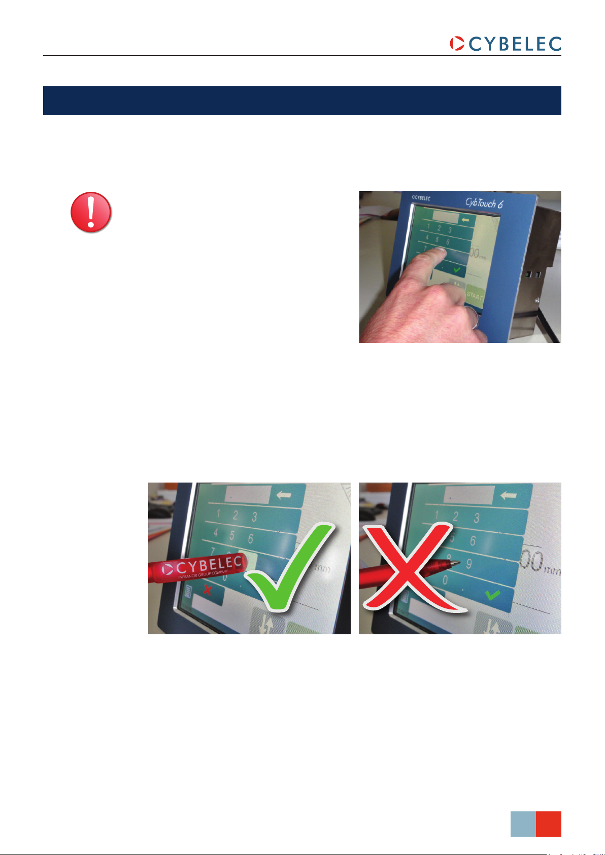
Touchscreens are pressure
sensitive.
Do not press down hard on the
screen.
Pressing hard on the screen will
damage the display. Such damage
is not covered by manufacturer
warranty!
Do not use sharp and/or pointed objects (sheet metal, screwdriver, metal pen ball, etc.) to
touch the screen; only use your fingers (with or without gloves on) or a plastic pen. Make
sure that your gloves do not have metal particles encrusted in the finger tips as they may
also damage the screen.
Take a few minutes to practice pressing gently on the screen, you will find that the screen
is very reactive and it is pleasant to use.
Sept.
2014
V3.1
3/38
Page 12
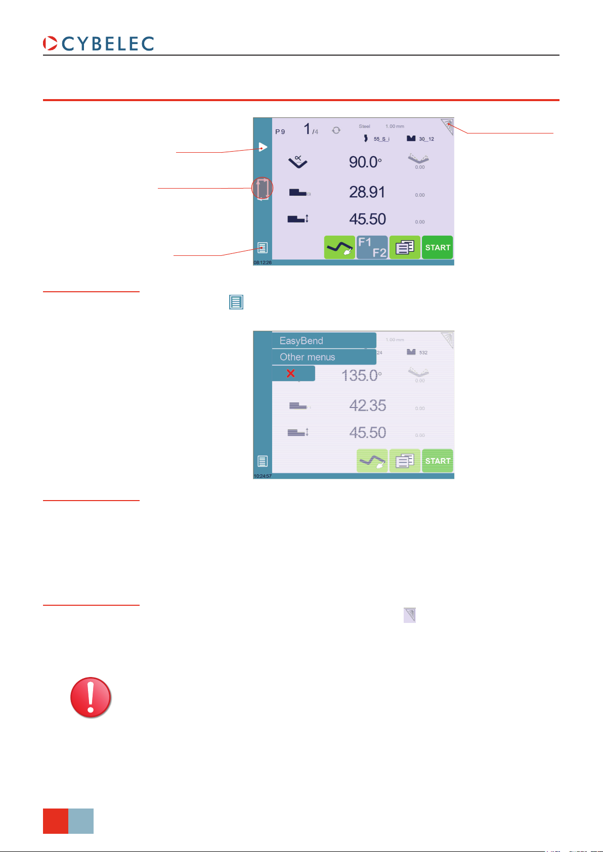
General naviGaTion
CybTouch 12 PS User Manual
Menu Button
Add step
or next step
Status Pages Zone
Menu Button
Screen Cleaning button
The Menu button allows you to directly select (jump to) the desired screen. The
content of the menu changes contextually.
Status Pages Zone
Screen Cleaning
The Status pages zone gives access to the Status page (see page 5). This is really a
zone that is active at any moment from any page (except the wizard’s).
To clean the screen while the CybTouch is on, touch the button.
Use only a damp and smooth cloth with soap or a neutral detergent.
NEVER use solvent, petrol, benzene, alcohols, etc.
4/38
Sept.
2014
V3.1
Page 13
CybTouch 12 PS User Manual
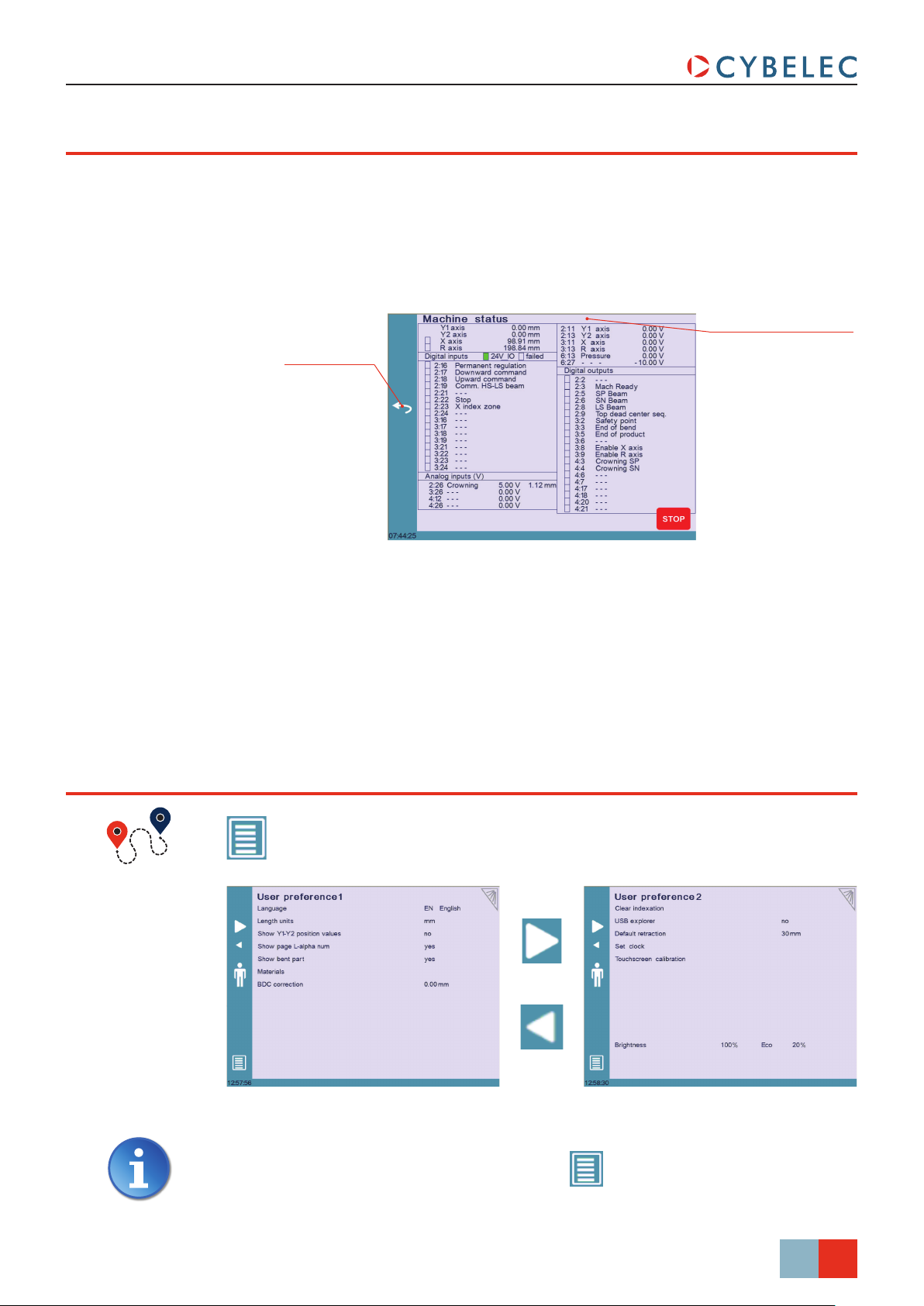
STaTuS paGe
The Status page shows the status of all inputs and outputs and axes positions of the NC.
This feature is very useful during setup or during phone service with a machine installed in
the field.
This page is accessed from anywhere by pressing the Status Pages Zone (see page 4).
To exit the Status page, press on the arrow on the left.
uSer preferenceS
Press arrow to
exit Status Page
On the upper line, a cycle
message may appear
indicating the cycle phase
the machine is executing
(Menu Button) → Other menus → User preference
To exit the User Preference page, touch the button.
Sept.
2014
V3.1
5/38
Page 14
CybTouch 12 PS User Manual
Language
Length Units
To browse through the available languages, simply touch Language on the screen.
Available languages are:
• EN English.
• BR Brazil.
• CN 中文.
• CZ Český.
• DE Deutsch.
• ES Español.
• FR Français.
• IT Italiano.
• NL Nederlands.
• TR Türkçe.
• TW 台灣.
The list of available languages is subject to change and may increase over time.
This parameter allows choosing between mm, inch and none for the length unit to be
used in the CybTouch.
When none is selected, the units are millimeters.
Show Y1-Y2 position values
Show page L-alpha num
This function will display the Y1 and Y2 axes positions on the Bend Numerical Page (see
page 14).
• When set to no, the position of axis Y1 is displayed during the beam’s movements.
• When set to yes1, the positions of the beam’s axes are displayed during the beam’s
movements.
• When set to yes2, the positions of the beam’s axes are constantly displayed under the
angle/beam’s position line.
When set to yes, this parameter gives access to the L-Alpha Mode (see page 27). This
button
is then displayed on the TouchProfile Mode page.
Show bent part
Sept.
6/38
2014
V3.1
This parameter, when activated, lets the operator see the state of the part before and after
the bend in the Automatic Bend Sequencing (optional) page.
Page 15

CybTouch 12 PS User Manual
Materials
Touching Materials opens the Materials page, where the default characteristics for each
material can be changed, or a new material can be configured.
This page may not be available, depending on the machine parameters’
configuration. To be allowed to access the Materials page, a level 2 password is
required.
The Materials page displays:
• Material: Selected material (here Steel).
• Default thickness for the material.
• Default sigma: Default sigma for the material (here 45).
• Displayed: If the material will be available to be selected for use (here yes).
• Thickness min/max: determines the maximum and minimum accepted thickness for
the selected material.
Three predefined default materials are available (steel, stainless steel, aluminum), but
others can be added.
To add a material:
1. Touch Material and select a non-configured material (Mater X) from the list.
2. Enter the new material’s characteristics.
3. Touch the name (Mater X) to display the keyboard and enter the name of the new
material.
BDC correction
This parameter allows the operator to apply a permanent correction to the Bottom Dead
Center position.
Please note that this correction is always applied and is NOT shown in the
correction page. If you experience big differences from what you expect to get,
maybe check the value of this parameter.
Sept.
7/38
2014
V3.1
Page 16

CybTouch 12 PS User Manual
Clear indexation
USB Explorer
Default retraction
When activated, this function clears the index and the machine will search for them, as
it does when turning the power on, allowing the operator to re-index its machine without
turning it off.
When this parameter is set to yes, it is possible to browse the USB key from the USB
transfer screen.
This parameter allows defining the default value displayed in the More Page (see
page 14) when activating the back gauge retraction function.
Set Clock
Touchscreen Calibration
Allows the user to set the time and date on the CybTouch.
Touch the eld you
want to modify
As a tall operator will tend to touch higher than a smaller one on the screen, this function
allows the calibration of the touch screen, and also makes sure that it is operating
correctly.
Use the up and down
arrows to modify the
selected eld
Setting inStructionS:
Simply follow the instructions on the page to calibrate the touchscreen.
8/38
Sept.
2014
V3.1
Use your finger or the plastic tip of a pen to calibrate the
Touchscreen. Never use sharp objects as this will damage the screen.
Page 17

CybTouch 12 PS User Manual
Brightness xx% Eco xx%
Here the brightness of the screen for normal mode and Eco mode can be defined:
1. Touch the mode for which you want to modify the brightness.
2. Use the
Manual axeS MoveMenT
In the course of setting up a machine, it is sometimes necessary to be able to move the
axes manually, for example when changing the tooling. This can be done on this page.
(Menu Button) → Other menus → Manual movement
movement not allowed)
Move beam up
(button hidden if
buttons to set the brightness.
Set here the bending force
that will be applied to the
manual movement
Desynchronized Beam
Menu Button
Setting inStructionS:
1. Select the axis that you want to move:
•
•
•
2. Touch the buttons to move the selected axis.
3. Use the foot switch (Low Speed Down movement) and this button
Up) to move the beam.
When the padlock is open
movement) Y1 or Y2 only. This is an easy way to return an unsynchronized beam back to
parallel to the table.
for the back gauge X axis.
for the back gauge R axis.
for the crowning axis.
(High Speed
, it is possible to select and move (Low Speed Down
Sept.
2014
V3.1
9/38
Page 18

Service paGe
CybTouch 12 PS User Manual
(Menu Button) → Other menus → Service → Service
Set Axis
Maintenance
Allows the operator to manually adjust the position of the back gauge (axes X and R) and
the beam (axes Y1 and Y2).
This function must be used with utter care and only by experienced
personnel. Wrong settings may mechanically damage the machine.
Settings are lost after indexing the machine.
The Maintenance page displays the hardware status of the CybTouch and lets the
operator perform different maintenance actions.
(Menu Button) → Other menus → Service → Service → Maintenance
10/38
Sept.
2014
V3.1
All the following actions require codes and should only be performed by
technicians or upon request of a technician.
Page 19

CybTouch 12 PS User Manual
Defrag
This function will rearrange the memory space of the CybTouch. Simply touch it and
follow the instructions given in the yellow pop-up window.
Format
This function will erase all data in the CybTouch. Only use this with the help of a
technician.
Internal backup
This function is specially designed for OEM and support.
Usually a machine parameters’ backup is made by the machine manufacturer or the
company who services the machine. This backup allows a maintenance technician to
restore original working parameters if necessary.
Should there be a need to restore parameters, call on a maintenance technician and
follow his instructions.
Information
Do not try to use this function unless you are in dire need.
Before using this last function, make sure that all your files have been
transfered outside the CybTouch (see USB Transfer, page 13).
The Information page displays the names and versions of the softwares installed on the
CybTouch. Pressing the Advanced button shows more detailed information.
(Menu Button) → Other menus → Service → Service → Information
To Advanced information
Sept.
11/38
2014
V3.1
Page 20

CybTouch 12 PS User Manual
Configuration
options
Touching this menu opens the following page, where one can find the computer’s
identification and manage the machine’s options.
(Menu Button) → Other menus → Service → Service → Configuration options
Serial number
This is the serial number of the CybTouch. It is entered at the factory at the end of the
machine’s initial setup and is related to the machine’s option list.
Changing the serial number means that all the options installed on the
machine can be lost.
Computer ID
This line displays an identification code that is unique to each CybTouch and guarantees,
together with the serial number, a correct identification of the machine.
Option list
This function opens a yellow pop-up window where all the options installed on the
CybTouch are displayed.
New option code
The function opens an alphanumerical pad where the code of the new option must be
entered. The format of an option code is: ABC-DEF-GHI-JKLM
12/38
Sept.
2014
V3.1
Page 21

CybTouch 12 PS User Manual
uSb Tr anSfer
This function opens the USB transfer screen, which allows the operator to transfer data
between the CybTouch and a USB key.
(Menu Button) → Other menus → USB transfer
Select the les you
want to transfer by
touching their name
Machine les listDie list
Punch list
Direction of transfer
Program list
Importing parts from other Cybelec NCs
Return to User Preferences Transfer button
CybTouch 12 is delivered with Cybelec’s off-line software PC1200, which controls most of
the other numerical controls produced by Cybelec.
From version S1, PC1200 includes CybTouchConverter, which allows you to convert parts
to the CybTouch format, and import them into your machine with the above mentioned
function.
Sept.
2014
V3.1
13/38
Page 22
baSiC PaGe deSCriPtion
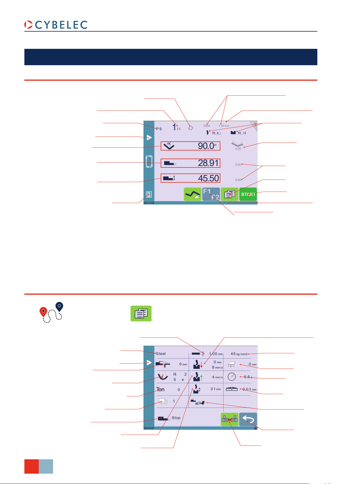
bend nuMerical paGe
CybTouch 12 PS User Manual
Repeat sequence button
Current step (sequence) number
Program number
Add step or next step
Beam (Y axis) position
value / bend angle
Back gauge (X axis)
position / ange length
Back gauge (R axis)
position value (optional)
Menu Button
(inactive here)
Material used and thickness
Current cycle activity information
Tools Management
Bend Correction
Back gauge (X & R axes)
Correction
More Page
Start – Stop
Interactive message line
TouchProle Mode
More paGe
Bend Numerical Page →
Material thickness
Material
Next step
Back gauge retraction
Step bending
Force
Number of parts
Back gauge nger type
Slow speed return
Opening (TDC)
Speed change threshold and bending speed
Material sigma
Bending length
Dwell time
Crowning
Back gauge manual
control
Return to Bend
Numerical Page
LazerSafe
14/38
Sept.
2014
V3.1
Page 23

CybTouch 12 PS User Manual
Available functions on the More page
The More page displays parameters related to the part, and depending on the CybTouch
configuration and the type of action performed, it also displays various settings for the
current bend.
Material
This is not a sequence parameter, but of course a part parameter. Each touch on the
material’s name selects the next available from the list of Materials (see page 7).
Material thickness
The default thickness, defined in Materials (see page 7), is automatically displayed
when changing material. It is however possible to change it simply by touching this icon.
This is also of course a part parameter.
Material sigma
The default sigma, defined in Materials (see page 7), is automatically displayed when
changing material. It is however possible to change it simply by touching this icon. This is
also of course a part parameter.
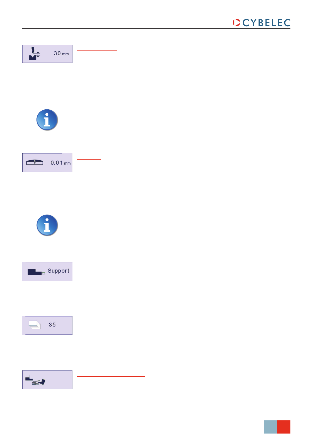
Back gauge retraction
The back gauge retraction can be activated/deactivated at its Default retraction (see
page 8) value using this icon. It is possible to modify the value by touching it. This is a
sequence parameter, meaning it can be modified with each step of the program.
Speed change threshold and bending speed
The distance parameter allows the operator to increase the height of the speed change
point. The speed parameter allows decreasing the bending speed from its maximum value
defined in the machine parameters.
Bending length
This parameter defines the width of the sheet metal part that will be pinched between the
tools. It is used to calculate the bending pressure.
If this parameter is not activated (gray), the CybTouch will not calculate the
bending Force and the Crowning.
Sept.
15/38
2014
V3.1
Page 24

CybTouch 12 PS User Manual
Step bending
When a large radius bend has been programmed (see L-Alpha Mode, page 27), its
parameters are displayed here. It is possible to modify them directly here.
Programming 99 x will automatically calculate the maximum possible step bends. The
resulting value may be reduced. However, if it is increased over the maximum calculated
value, the resulting radius and angle will be drastically affected.
The large radius bending function is deactivated when this field is grayed.
Slow speed return
This parameter allows slowing down the speed of the beam after the bend, and is
generally used when the part has a long flange and the operator tries not to let it “fall
down too fast”.
The beam will return at low speed up while the operator holds the foot pedal. It switches
to high speed up when either the pedal is released or Pinch Point is reached, whichever
comes first.
When this field is deactivated (grayed), the beam moves back up directly at HSU
(High Speed Up).
Dwell time
Allows defining the duration of the dwell time, meaning the time during which the punch
remains at BDC before coming back up.
When this field is deactivated (grayed), the default Dwell Time value defined in
the machine parameters is applied.
16/38
Sept.
2014
V3.1
Force
The force is automatically calculated by the CybTouch, according to the Material, the
Material thickness, the Material sigma and the Bending length. The value can also be
manually modified here.
Page 25
CybTouch 12 PS User Manual
Opening (TDC)
For parts created with a profile (see TouchProfile Mode or L-Alpha Mode), this value is
automatically calculated to allow the operator enough room to extract its bent part from
between the tools. It is however possible to change it manually.
For part created manually (see Numerical Mode), this parameter uses the default
minimum value defined in the machine parameters. It can however be programmed here.
Creating a “New part” reinitializes it to its default value.
When this field is deactivated (grayed), the beam moves back all the way up to
its maximum limit switch.
Crowning
The crowning function is activated here. It is automatically calculated, according to
the Material, the Material thickness, the Material sigma and the Bending length. If the
crowning needs correction, use the Crowning (see page 29) function in the correction
page.
The value can be manually changed by operator. It will however be automatically
recalculated if any of the values used for its calculation is changed.
When the crowning function is deactivated (gray icon), the crowning system
physically remains to its last position and does not automatically return to
0.0 mm. Keep that in mind when using this function – or not – between one
sequence and the following.
Back gauge finger type
The back gauge dimensions are defined in the machine parameters. This function allows
browsing through the available support and stop positions of the back gauge. This
function may be available, or not, according to the machine configuration.
Number of parts
The operator can enter here the total amount of parts to be produced. Every time all
the sequences of the program are executed, hence a part is completed, this counter is
decreased of one unit. When the amount of parts is reached, a yellow pop-up window
signals it to the operator.
Back gauge manual control
Activating this parameter gives manual control over the back gauge movement. This
means the operator must personally give the start to the back gauge movement, using for
example the foot switch or the start button.
Sept.
17/38
2014
V3.1
Page 26
toolS ManaGeMent
Tools management allows the creation and configuration on the CybTouch of the tools to
be used on the machine. These tools are then taken into account in bend calculations.
Once a punch and die are created and selected, you can select the bend angle you require
as well as the flange length (L). The CybTouch then calculates the positions for axes X and
Y for the bend.
puncheS
Bend Numerical Page →
Punch name
Browsing through
existing punches
CybTouch 12 PS User Manual
Punch mounting direction
Basic punch data
Bottoming
Basic shapes of the punch
Punch more specic data
Return to Bend
Numerical Page
Touch the punch to
display its default shape,
allowing an easier
identication of the
various dimensions
18/38
Sept.
2014
V3.1
Setting inStructionS:
To select a punch, simply browse through the existing punches in your library using the
arrows buttons, and then return to Bend Numerical Page.
Page 27

CybTouch 12 PS User Manual
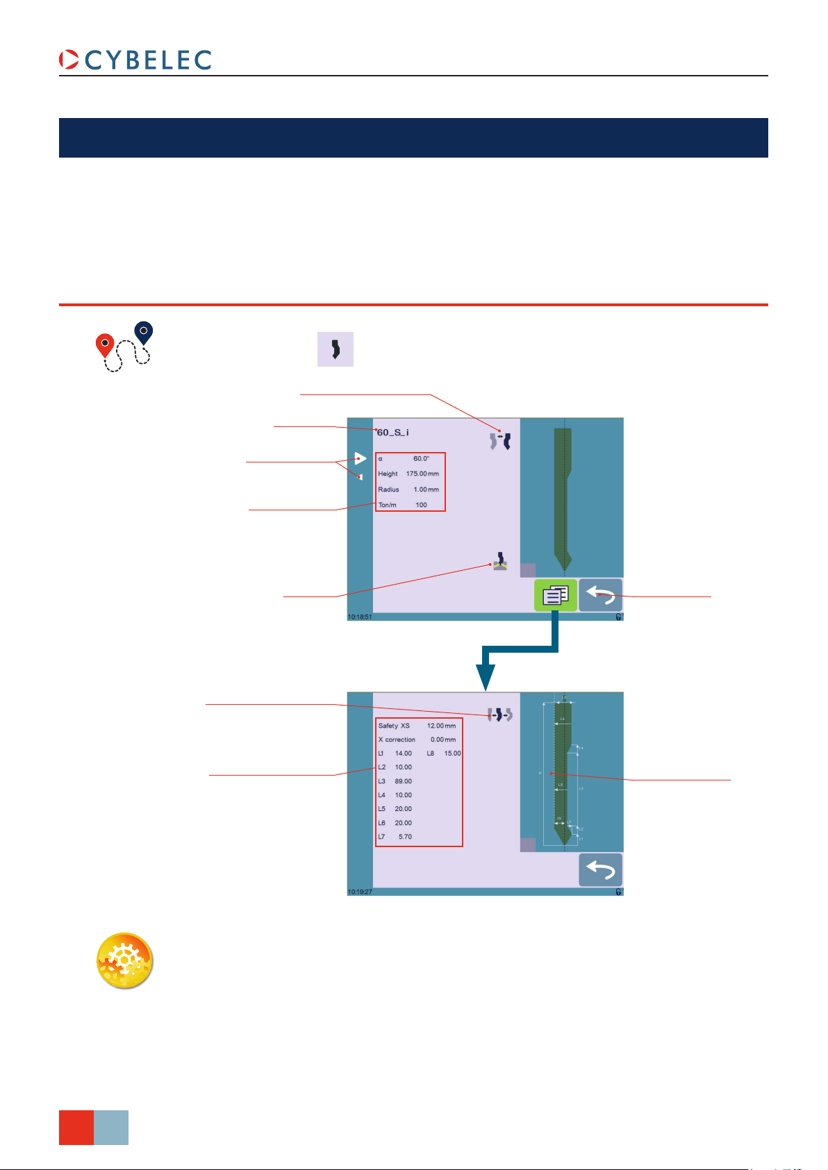
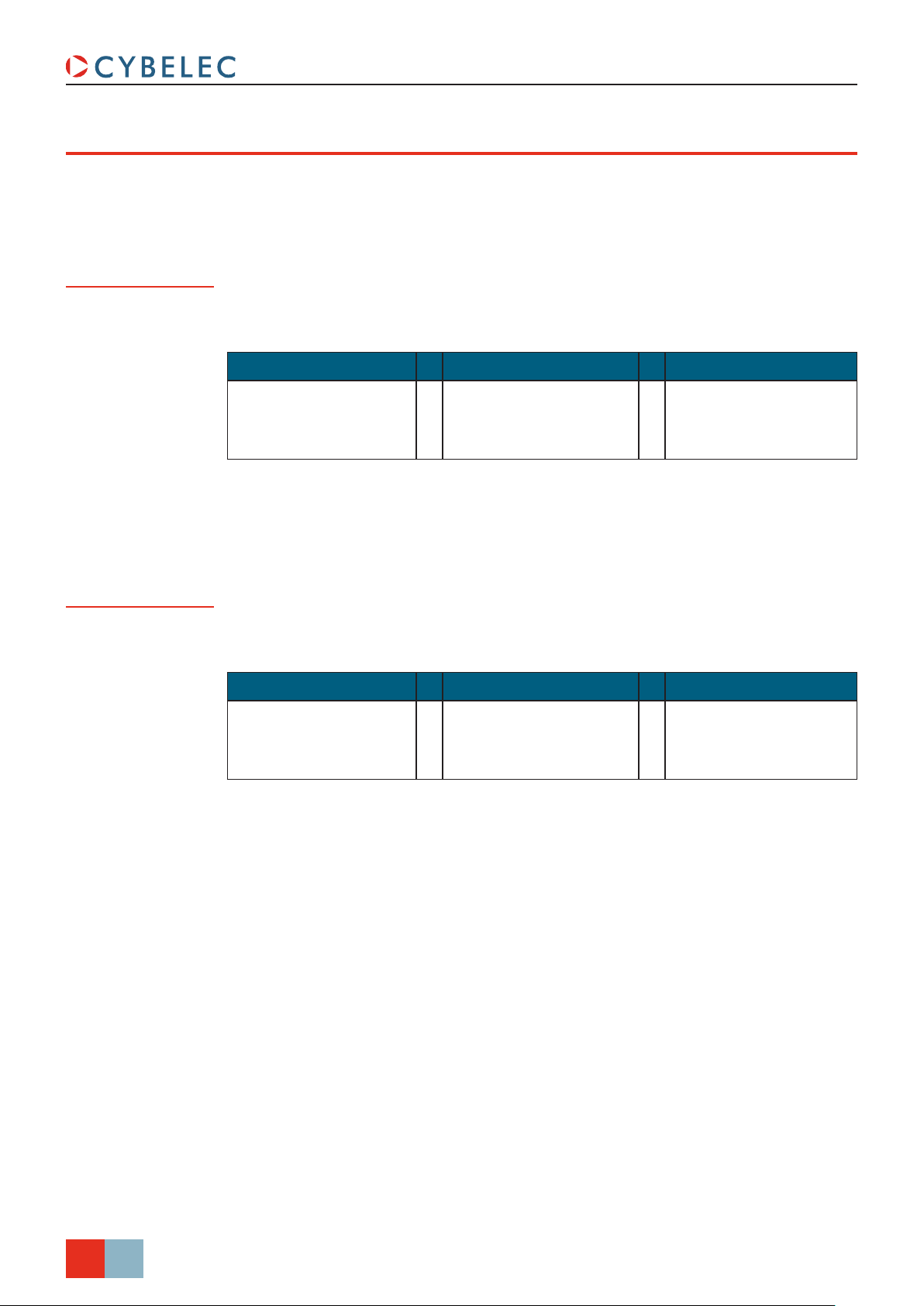
How to create or modify a punch?
If no punch is yet created, the punch will have no name (??? is displayed). If a punch
already exists, then the last punch used will be selected, here 60_N (modifications will
not alter the existing punch as they will be saved under another name).
1. Touch the punch icon
2. Enter the basic characteristics (α (punch angle), Height, Radius and Ton/m) for the
new punch to be created.
3. Touch the
4. Select the
5. Touch the
6. Select the punch type (straight, normal or gooseneck) with this icon
7. Enter the more specific dimensions L1 to Lx by referring to the graphic
representation on the right of the screen. Touching this image will display the default
representation of the tool, making it easier to identify the various dimensions.
button to invert the punch if necessary.
or icon to define the tool as resistant for bottoming.
button to display the More page.
to access the punch details.
.
The dimensions L1 to Lx are the same as the ones used in PC 1200, DNC 880S,
ModEva’s. If you use the same tools, print them from PC1200 to easily program
them in the CybTouch. Of course consider giving the same tools the same
name.
8. Enter the following values:
• Safety XS: Security distance between the tool and the back gauge for X axis.
• X correction: If the punch is not perfectly aligned.
9. Return to previous page
.
To be allowed to save a tool, a level 2 password is required.
10. Touch the punch name (here 60_S_i).
11. Touch Save punch to overwrite the existing tool or Save punch as if you want to
save your tool under another name.
12. Enter the name of the new punch using the alphanumerical keypad.
We recommend that you follow the naming conventions explained in Naming
Tools (see page 22).
13. Touching the button brings you back to the program page, with the punch you
just saved being selected and ready to be used.
Sept.
2014
V3.1
19/38
Page 28

dieS
CybTouch 12 PS User Manual
Bend Numerical Page →
Die mounting direction
Die name
Browsing through
existing dies
Basic die data
Bottoming
Die more specic data
Return to Bend
Numerical Page
Touch the die to display
its default shape, allowing
an easier identication of
the various dimensions
Setting inStructionS:
Selecting a die is the same as selecting a punch; simply browse through the existing dies
in your library using the arrows buttons, and then return to Bend Numerical Page.
20/38
Sept.
2014
V3.1
Page 29

CybTouch 12 PS User Manual
How to create or modify a die?
If no die is yet created, the die will have no name (??? is displayed). If a die already exists,
then the last one used will be selected, here 30_12 (modifications will not alter the
existing die as they will be saved under another name).
Ve
1. Touch the die icon to access the
Ve
die details.
R
2. Enter the basic characteristics (Ve,
R
α (die angle), Height, Radius and
Ton/m) for the new die to be created.
3. Touch the
button to invert the
die if necessary.
4. Select the
5. Touch the
or icon to define the tool as resistant for bottoming.
button to display the More page.
6. Enter the more specific dimensions L1 to Lx by referring to the graphic
representation on the right of the screen. Touching this image will display the default
representation of the tool, making it easier to identify the various dimensions.
The dimensions L1 to Lx are the same as the ones used in PC 1200, DNC 880S,
ModEva’s. If you use the same tools, print them from PC1200 to easily program
them in the CybTouch. Of course consider giving the same tools the same
name.
7. Enter the following values:
• Safety XS: Security distance between the tool and the back gauge for X axis.
• Safety RS: Security distance between the tool and the back gauge for R axis.
• Retr. zone: Retraction zone.
8. Return to previous page
.
To be allowed to save a tool, a level 2 password is required.
9. Touch the die name (here 30_12).
10. Touch Save die to overwrite the existing tool or Save die as if you want to save your
tool under another name.
11. Enter the name of the new die using the alphanumerical keypad.
We recommend that you follow the naming conventions explained in Naming
Tools (see page 22).
12. Touching the button brings you back to the program page, with the die you just
saved being selected and ready to be used.
Sept.
2014
V3.1
21/38
Page 30
naMinG ToolS
CybTouch 12 PS User Manual
It is recommended that you use naming conventions for your tools.
Below you will find a simple convention allowing you to precisely identify a punch or die
through its name.
Of course, depending on your needs you may need to create more rules for punch and die
naming.
Punches
Dies
The name of the punch should be built in the following manner: first its angle, followed by
its type, and then whether it is inverted or not.
punch anGle (°) punch Type inverTed or noT
30
60
90
Following these rules, here are some examples of punch names: 90_N_i, 60_G, 30_S,
and so on, and so forth.
The name of the die should be built in pretty much the same manner: first its width (Ve
dimension), followed by its angle, and then whether it is inverted or not.
_
N = Normal
S = Straight
G = Gooseneck
_ i = If inverted
ve (mm) die anGle (°) inverTed or noT
12
16
20
_
30
_ i = If inverted
86
22/38
Sept.
2014
V3.1
Following these rules, here are some examples of die names: 12_86_i, 16_86, 20_30,
and so on, and so forth.
Page 31

CybTouch 12 PS User Manual
CreatinG a Part ProGraM
There are three ways to create a program part: with the TouchProfile Mode, with the
Numerical Mode (see page 26), and with the L-Alpha Mode (see page 27).
In this chapter the machine is considered operational: machine parameters,
tools (see Tools Management, page 18), materials (see Materials, page 7),
etc. are already configured and programmed.
Touchprofile Mode
Bend Numerical Page →
Program number
Zoom button
To Automatic Bend
Sequencing (optional)
To L-Alpha Mode
In this mode, the operator can very intuitively draw a profile directly on the screen.
Setting inStructionS:
1. Touch the program number and select
New program in the list.
2. First select the material, its thickness
and the tools to be used for the part by
touching their respective icons.
3. Draw the profile by touching the
screen where you want to add a
segment.
Program number
Tools selection
Material and thickness
Touching this icon allows erasing
the last segment added.
4. Touch on the middle of a segment to
modify its value.
Sept.
2014
V3.1
23/38
Page 32

5. Touch on an angle to modify its value.
Touching the
icon will open a
yellow pop-up, in which it possible to:
CybTouch 12 PS User Manual
• Activate (and deactivate) a special
tool by touching its icon, and select
it from a list by pressing ???.
• Change the value of the radius (see
also Step bending, page 16) and
define how many steps the NC will
make to execute it.
6. Should it prove difficult to select
a particular segment or angle, it
is possible to zoom on an area by
touching this button and then on
the desired zone.
One can also choose to enter the
length and angle values in the L-Alpha
Mode page by pressing this
button.
7. Once all the segments and angles
are adjusted, press this button
to access the Automatic Bend
Sequencing (optional) (see page 24).
Special tools
Special tools
Maximum distance to
Maximum distance to
ideal curve
ideal curve
Number of steps to
Number of steps to
execute the step bending
execute the step bending
Large radius value
Large radius value
Activate/deactivate zoom
Activate/deactivate zoom
Toggle zoom in/zoom out
Toggle zoom in/zoom out
auToMaTic bend SequencinG (opTional)
Bend Numerical Page → →
Bend Numerical Page → →
Once the shape of the part has been defined, the bending sequence for the part can be
automatically determined by the CybTouch.
Delete last bend
Delete all bends
Setting inStructionS:
1. Simply touch the bend sequence calculation button . Once the sequence is
calculated, the Bend 2D screen is displayed.
Launch automatic bend
sequence calculation
Automatic bend sequence
calculation criteria
24/38
Sept.
2014
V3.1
2. If the option is not installed, simply touch the bend in the order that you want them
performed. A small number is displayed on the bend, indicating its position in the
sequence.
Page 33

CybTouch 12 PS User Manual
Pressing the back button will erase the last bend in the sequence. If you wish
to delete all bends, simply touch the
3. Immediately after determining the last bend to be selected, the Bend 2D screen here
Touch the drawing to
below is displayed.
Browsing through
the bends
toggle between
Bend Order page
and this one
button.
Next gauging point
Switch between stop or
support gauging
More Page
4. In the Bend 2D page, the operator must determine the back gauge and part position
for each bend, and if necessary the special parameters on the More Page (see
page 14).
5. Press
6. Start the hydraulic pump motor (by pressing this button
and select Bend num page to return to the Bend Numerical Page.
if available. It turns red
when the motor is running the button becomes red).
7. Press the
button to position the machine according to the data that were just
entered.
8. When the machine is ready to bend, a
button is displayed.
9. Press the foot switch to execute the bend.
Sept.
2014
V3.1
25/38
Page 34

nuMerical Mode
CybTouch 12 PS User Manual
It is also possible to simply create a part program directly on the Bend Numerical Page.
Current step (sequence) number
Program number
Add step or next step
Angle of the bend
Length of the ange
To TouchProle Mode
Material used and thickness
Tools selection
More Page
Setting inStructionS:
1. Touch the program number and select New program in the list.
2. First select the tools to be used for the part by touching their respective icons (see
Tools Management, page 18).
3. Touch the material’s name (here Steel). The More Page (see page 14) is displayed.
4. In the More Page, select the Material used, enter the Material thickness, the Bending
length, and other sequence parameters (Opening (TDC), Slow speed return, etc.).
5. Touch the
6. Touch the numerical value next to the angle icon
button to return to the Bend Numerical page.
, and enter the value for the
first bend you wish to create (here 90°).
7. Touch the numerical value next to the segment length icon
, and enter the value
for the first segment you wish to create (here 30.00 mm).
8. Add the next bend to the program by touching
.
9. Proceed in the same manner to create the other segments of the part.
10. Touch
11. Start the hydraulic pump motor (by pressing this button
to return to the first bend.
if available. It turns red
when the motor is running the button becomes red).
12. Press the
button to position the machine according to the data that were just
entered.
13. When the machine is ready to bend, a
button is displayed.
14. Press the foot switch to execute the bend.
26/38
Sept.
2014
V3.1
Page 35

CybTouch 12 PS User Manual
l-alpha Mode
Bend Numerical Page →
Bend Numerical Page →
Program number
Segment length
Angle value
More parameters for step
To Automatic Bend
Sequencing (optional)
To TouchProle Mode
This page is only available if user preference Show page L-alpha num (see
page 6) is set to yes.
In this mode, the operator can define each step (length or angle) of a profile on a table.
Setting inStructionS:
1. Touch the program number, select
New program in the list and press
this button
to access the L-alpha
mode.
2. First select the material, its thickness
and the tools to be used for the part by
touching their respective icons.
3. Touch the first value in the table (here
200.00). The window to the right is
displayed.
4. Enter the value for the first segment’s
length and touch the
button to add
another step.
Program number
Tools selection
Material and thickness
Step number
Step value
Browsing through
the steps
Click on OK when prompted to create
new step.
5. Proceed in the same manner for all
steps and angles of the profile.
6. If a bend needs special parameters
(large radius, special tool), press in
the more field of the corresponding
sequence.
A special punch or /and die means
there must be an additional working
station.
Sept.
2014
V3.1
27/38
Page 36

7. A yellow pop-up is displayed, in which
it possible to:
• Activate (and deactivate) a special
tool by touching its icon, and select
it from a list by pressing ???.
• Change the value of the radius.
CybTouch 12 PS User Manual
Special tools
Special tools
Max. distance to
Max. distance to
ideal curve
ideal curve
Number of steps to
Number of steps to
execute the step bending
execute the step bending
bend correcTion
• Define how many steps the NC will
make to execute the step bending.
8. A small More icon shows that
something special is programmed on
the bend.
9. To remove the icon (and special
parameters), return to the yellow popup, touch all the activated functions to
make them turn gray, and select OK.
10. Once all the segments and angles
are adjusted, press this button
to access the Automatic Bend
Sequencing (optional) (see page 24).
Large radius value
Large radius value
More icon – means
More icon – means
special functions on bend
special functions on bend
Touching a step number allows deleting it
Touching a step number allows deleting it
or inserting a new one right after it
or inserting a new one right after it
Angle Correction (Y axis)
All program corrections are made in the Bend Numerical Page (see page 14).
Corrections can be made to:
• The angle (Y1 + Y2, see Angle Correction (Y axis) and/or crowning if available, see
Crowning, page 29),
• The back gauge position (X and R, if available), see Back gauge (X & R axes)
Correction, page 29.
After physically measuring the angle, if corrections are to be made, they must be done on
this page, and not directly in the program step.
Bend Numerical Page →
Angle correction
Y1 axis correction
Pinch Point correction
Crowning correction
Y2 axis correction
X axis correction
R axis correction
28/38
Sept.
2014
V3.1
Page 37

CybTouch 12 PS User Manual
Setting inStructionS:
1. Touch the angle correction icon,
Pressing this button will reset all
angle corrections.
2. Depending on the position of the sheet metal in the press, it may be necessary to
and enter the physically measured
value of the angle. The numerical
control will automatically calculate the
Y1 and Y2 axes corrections.
fine-tune the beam’s corrections. It is possible by simply touching this
icons, and entering the desired values.
Reset corrections button
Reset corrections button
or this
Crowning
Back gauge (X & R axes) Correction
3. Corrections to the crowning value can be made by touching this icon
4. The numerical control automatically calculates the Pinch Point height. If it needs
correction, it can be done by touching this icon
.
.
The grayed value next to the Pinch Point correction icon is the value calculated
by the numerical control, and thus the value onto which the correction will be
applied.
5. Touching this icon allows applying a correction to the back gauge X axis
position.
6. Touching this icon
position.
allows applying a correction to the back gauge R axis
The grayed values next to the back gauge correction icons are the value
calculated by the numerical control, and thus the values onto which the
corrections will be applied.
The back gauge positions corrections can also directly be made on the Bend
Numerical Page (see page 14).
Back gauge (X axis)
position correction value
Back gauge (Y axis)
height correction value
Sept.
29/38
2014
V3.1
Page 38

SavinG and loadinG a ProGraM
SavinG a proGraM
After creating a program, an operator can save the program in order to use it again:
1. In the Bend Numerical Page, touch the Program number (e.g. P0).
2. Touch Save program.
CybTouch 12 PS User Manual
loadinG a proGraM
To call (load) a program:
3. Enter the number you wish to give to the program (e.g. 1 for P1), followed by
4. The program is now called P1 and is saved in the CybTouch.
1. In the Bend Numerical Page, touch the Program number (ex: P1).
2. Touch Call program.
3. Select the program to be loaded from the list (e.g. 002 for P2).
4. The selected program (P2) is then loaded into the work memory and is ready to be
used.
.
deleTinG a proGraM
To delete a program:
Sept.
30/38
2014
V3.1
1. In the Bend Numerical Page, touch the Program number (ex: P1).
2. Touch Delete program.
3. Select from the list the program to be deleted.
4. Touch
to confirm.
Page 39

CybTouch 12 PS User Manual
eaSybend PaGe
The EasyBend page is used for individual bends, for example when an external worker
needs to interrupt production just to make a single bend (usually with the same tools).
(Menu Button) → EasyBend
The program currently being used for production is only temporarily interrupted
(no need to save it) when switching to the EasyBend page, and then resumed
again when returning to the program page (Menu Button → Current program).
MakinG a bend on The eaSybend paGe
See Basic Page Description, page 14 for more information on the different
controls on the EasyBend page.
Setting inStructionS:
1. Touch the material’s name (here Steel). The More Page (see page 14) is displayed.
Select the Material (see page 15) used, enter the Material thickness and the
Bending length.
2. Touch one of the tool’s icon (
configure tools, please refer to section Tools Management, page 18.
3. Enter the angle
4. Enter the flange’s length
5. Enter the back gauge height value
or ) to select a punch or die. To learn how to
for the first bend you wish to create (here 90°).
(here 100.00 mm).
(here 34.00 mm)
6. Press this button
eventually required extra data for the bend.
7. Start the hydraulic pump motor (by pressing this button
when the motor is running the button becomes red).
8. Press the
entered.
9. When the machine is ready to bend, a
10. Press the foot switch to execute the bend.
button to position the machine according to the data that were just
to go to the More Page (see page 14) and enter the
button is displayed.
if available. It turns red
Sept.
31/38
2014
V3.1
Page 40

error and warninG MeSSaGeS
Following is a list of warning and error
messages which may be displayed on the
interactive message line of the CybTouch.
There are two types of messages:
• Warning Messages, which are displayed on a green background. They are information or instructions that will disappear automatically.
• Error Messages (machine or NC
errors), which are displayed on a red
background. They inform the user of an
error occurring on the machine or NC,
and sometimes require intervention by
the end user or a technician.
When reporting error messages, please ALWAYS indicate the error number at
the end of the line. This number also refers to the first column in the section
below.
Interactive
message line
CybTouch 12 PS User Manual
Message number
WarninG MeSSaGeS
MSG nr. MeSSaGe deScripTion
W01 Not implemented This message is displayed when a function is in development but
not yet fully implemented.
W02 Ignore This message appears when the desired action makes no sense,
like for example clearing the indexation when the indexation was
not made.
W03 Code accepted This message is displayed when the correct password has been
entered.
W04 Please press 2 seconds This message reminds the operator to keep the start pump
button
W05 The pump is on This message appears after the pump starting cycle has been
correctly executed.
W06 The pump is off This message indicates that the pump has been stopped.
W07 Select at least one bend This message is displayed when the operator tries to go to the
Bend 2D screen from the Bend Order screen before defining
the first bend of the sequence (see Automatic Bend Sequencing
(optional), page 24).
W08 Touch OK to continue Indicates that a validation is required to continue.
W09 Step n° This message appears in the More Page (see page 14), it
indicates the step sequence number when browsing through the
program’s steps.
W10 Cycle in progress While this message is displayed, the machine cycle is in progress
and the screen is locked, except for the Stop button.
W11 Machine is indexed Indicates the indexation cycle was successful.
W12 Identification OK In the Axis Wizard, indicates the identification cycle was
successful.
pressed for 2 seconds.
32/38
Sept.
2014
V3.1
Page 41
CybTouch 12 PS User Manual
MSG nr. MeSSaGe deScripTion
W13 Touch the zoom center
W14 Touch to create a new
segment
W15 Touch one length or angle to
start the profile
W16 Eco mode This message appears when the Eco mode starts, after the timer
W17 Enter the measured angle This message is displayed when the operator must enter the
W18 Empty field Operator did not enter a value.
W19 24V I/O power on 24V to the inputs/outputs is now available.
W20 Please select a field This message is displayed when trying to set the time (see Set
W21 Set seconds
W22 Set minutes
W23 Set hour
W24 Set day
W25 Set month
W26 Set year
W27 Touch the small graphic to
toggle screen
W29 End of list This message is displayed when reaching the end of the list in
W30 Serial number from 100’000
thru 231’071
W31 New option code When installing a new option in the Service Page (see
W32 Data entry in progress Operation impossible: data entry in progress. Wait until the data
W33 Indexation in progress Operation impossible: indexation in progress. Wait until the
W34 RFlink disconnected When the RFLink connection to a laptop has been shut down
W35 Access not allowed Operator needs another level password.
W36 Beam not at TDC, move beam
up
W37 Moving direction has been
inverted
W38 Counting direction has been
inverted
When the zoom function
is activated, indicates that the HMI
will zoom around the next touch on the screen.
When creating a new part in the TouchProfile Mode (see
page 23), this message reminds the operator to touch the
screen to create a part’s segment.
When creating a new part in the L-Alpha Mode (see page 27),
reminds the operator to touch the table to begin creating a part.
defined in the machine parameters is over.
physically measured angle value in the Bend Correction page.
Clock, page 8) and no field (minute, seconds, etc.) has been
selected.
In the Set Clock (see page 8) page, when the corresponding
field is selected, indicates that it can be set using the up and
down arrows.
This message appears once at the beginning of the bend manual
sequencing, telling the operator that he can toggle from the Bend
Order page to the Bend 2D page simply by touching the graphic
at the bottom of the screen (see Automatic Bend Sequencing
(optional), page 24).
one of the different menus
.
This message appears only when entering the serial number. It
indicates the range of the number to be entered. Attention, this
operation is normally done at the factory, with a serial number is
related to the options installed on the machine. Do not change it!
page 10).
is entered to try again.
indexation is finished to try again.
from the latter.
Wizard message: Rotary direction of the motor has been
changed.
Wizard message: Counting direction of the axis has been
changed.
Sept.
2014
V3.1
33/38
Page 42

CybTouch 12 PS User Manual
MSG nr. MeSSaGe deScripTion
W39 Moving and counting
directions have inverted
W40 OK Indicates a cycle or operation has properly ended.
W41 No movement executed
W42 Enter next measured angle When using double or triple angle measurement, tells the
W43 OK, correction done Appears when an angle correction has been entered and applied.
W45 Enter unlock interface
password
W46 Enter password level 1 or
greater
W47 Enter password level 3 This message is displayed when a password of level 3 or higher
W48 Enter new password
W49 Confirm new password
W50 Enter password for backup This message is displayed when trying to create a backup.
W51 Enter password for restore This message is displayed when trying to restore a backup.
W52 Enter password for init This message appears on the page displayed after the system
W53 Enter password for delete all
backups
Wizard message: Both the rotary direction of the motor and the
counting have been changed.
Axis Wizard message: Operator pressed
but no movement
was made.
operator to enter the next measured value.
This message is displayed when parameter P02.04 Level 0 Lock
HMI is set to yes and the screen is touched.
This message is displayed when a password of level 1 or higher
is needed to execute a specific operation.
is needed to execute a specific operation.
These messages are displayed when changing passwords.
crashed (soft or hardware problem), when the operator tries to
format the machine.
This message is displayed when trying to delete all backups.
34/38
Sept.
2014
V3.1
Page 43
CybTouch 12 PS User Manual
error MeSSaGeS
MSG nr. MeSSaGe deScripTion
E02 Pump motor off The pump motor needs to be on for the sequence to start.
E03 Buffer Full The part-program memory is full, you cannot add another
sequence.
E04 Code refused The level code to access the selected page is not correct. Try
again or ask for it if you do not have it.
E05 File not compatible The loaded part-program is incompatible with the NC. This part
should be deleted.
E06 Machine parameter file
problem
E07 Machine parameters not
compatible, please format data
E08 Lismisc File not compatible Information message, which will disappear when restarting the
E09 Save program problem This file is corrupt and cannot be saved. Try to restart the NC. If
E10 File not found [ ] A file is missing and the code indicates which one. Call Cybelec
E11 Write to file problem This file is corrupt and cannot be saved. Try to restart the NC. If
E12 X under minimum limit Operator entered a value under the limit, or a memorized value in
E13 X over maximum limit Operator entered a value over the limit, or a memorized value in
E14 Fw SetVar Error [ ] May occur when a feature is configured, but the dedicated input/
E15 Bottoming not allowed This message is displayed when a bottoming sequence is
E16 Fw Axes Error [ ] ... Axis manager error. The number gives more information. Most
E17 Programming error Machine parameters incorrectly configured, the error page is
E18 No Backgauge defined All the back gauges programmed in Machine Parameters have
E19 Quantity = 0 When pressing start, the programmed amount of parts to
E20 Cycle repeat = 0 Cannot start cycle because repeat cycle function is set to “0”.
This file is corrupt and cannot be saved. Try to restart the NC. If
the problem persists, format the memory.
This message appears when a software update has been made
over a much older version and the parameters are no longer
compatible. It can also appear if the uploaded parameters (with
RFlink) are much older or newer than the current software
version and they are not be compatible. A new start up of the
machine must be made. Contact your dealer.
NC.
the problem persists, format the memory.
with this code to know which file is missing.
the problem persists, format the memory.
the program is under the limit. The wrong value flashes and must
be corrected.
the program is over the limit. The wrong value flashes and must
be corrected.
output is not configured. Usually this is solved by loading the
default input/output configuration (see the machine parameters).
programmed and bottoming is not allowed with either one of the
tools.
common errors are described in messages E55 to E68.
If other error numbers are listed, please send conditions of
problem, traces and parameters to the Cybelec Technical support
for assistance.
displayed.
none selected for mode. Select at least one mode other than
none.
be made is ‘0’. See Number of parts, page 17 for more
information.
Sept.
2014
V3.1
35/38
Page 44

CybTouch 12 PS User Manual
MSG nr. MeSSaGe deScripTion
E21 No material defined (define
one or more in MP)
E24 Identification Error [ ] During the Axis Wizard, there was an error identifying one of the
E25 No FAST task running [ ] Switch OFF the machine for 1 min and restart it again.
E26 NULL pointer to axis struct. This message indicates a software bug. Write it all down and
E27 MUTEX Error [ ] This message indicates a software bug. Write it all down and
E28 I/O no 24V or overload (output
in safety off)
E29 Radio link error, code [ ] The RFlink chip has detected an error. Check the environment
E30 Touchscreen error, code [ ] Please contact your machine dealer with this specific code and
E31 “Crowning” analog input not
configured
E32 “Crowning” analog output not
configured
E33 Syntax error in XML file This file is corrupt and cannot be used. Try to restart the NC. If
E34 Memory allocation problem
(xml)
E35 Endless loop on process task Process error. Please restart the NC and inform your dealer.
E37 WARNING: Overloop intern This error should normally never happen on the machine. It
E38 Unknown key There is a list of known screen zones, and the pressed zone is
E39 “Start” input refused The start command is not accepted in this page/situation.
E40 R under minimum limit The programed position value for axis R is below the value of the
E41 Thickness smaller than min The thickness entered for the material is below the minimum
E42 Thickness greater than max The thickness entered for the material is above the maximum
E43 Configuration error Input/output incorrectly configured in machine parameters, the
E44 “External stop” input is active External stop may be caused by safety devices, emergency
No materials programmed in the Material pages (in User
preferences). A material must be selected to perform
calculations.
axes. The error number (typically E55, E56 or E57) gives more
information. See also message E16.
contact Cybelec.
contact Cybelec.
The 24V power supply for the inputs/outputs is no longer present
or an output is overloaded. Reset any safety device on the
machine, check protection grids and rear guards are closed, etc.
If the problem persists, switch machine OFF for 3 min and restart
it again. If the problem still persists, check the machine manual
and/or ask a service technician to check your machine.
for disturbances (cell phone, wi-fi) and that the material works
properly. If the problem persists, write the error number down
and send it Cybelec.
details.
While configuring (setting up) the NC, the Crowning dedicated
input was not configured but is requested to run properly.
While configuring (setting up) the NC, the Crowning dedicated
outputs were not configured but are requested to run properly.
the file is a part-program, try to delete it.
There was a problem while trying to read a file in the memory.
The file is probably corrupted. The number gives more
information, write it down.
means there are too many elements in a coded list.
not in it. This error can normally not happen in the field.
minimum limit switch position.
value defined in the User Preferences (see Materials, page 7).
value defined in the User Preferences (see Materials, page 7).
error input/output page is displayed. Check for unauthorized
doubled output or inputs.
This message can also be displayed if the chosen configuration
requires more icons on the first page than there room available.
buttons, rear protection guards, etc. See machine instructions.
36/38
Sept.
2014
V3.1
Page 45

CybTouch 12 PS User Manual
MSG nr. MeSSaGe deScripTion
E45 Error: backgauge “rest” mode
and retract
E46 “Pressure” analog output not
configured
E47 R over maximum limit The programed position value for axis R is above the value of the
E48 Stop doesn’t exist This error means the operator is trying to make a bend without a
E50 Value out of limit This message is displayed when the value the operator is trying
E51 Error[ ][ ][ ][ ]... Internal management error. Write the error’s codes down and
E52 Punch does not exist This message is displayed when trying to create a new part
E53 Die does not exist This message is displayed when trying to create a new part
E55 Identification Error 1 (No
motion detected)
E56 Identification Error 2 (Not
enough oscillations)
E57 Identification Error 3
(Amplitude of the oscillation)
E58 Fw Axes Error 32 [Trajectory
tracking error]
E59 Fw Axes Error 311 [MaxSpeed
too high !]
E60 Fw Axes Error 312 [MaxSpeed
too small !]
E61 Fw Axes Error 313
[Acceleration too small or
MaxSpeed too high !]
E62 Fw Axes Error 314
[Acceleration too high or
MaxSpeed too small !]
E66 Fw Axes Error 33 [Maximum
voltage time exceeded (10V)]
E67 Fw Axes Error 39 [Speed
tracking error]
E68 Fw Axes Error 316 [MinPosition
or MaxPosition outside limit ! ]
It is not allowed to program a Back gauge retraction (see
page 15) with a support type of back gauge finger.
While configuring (setting up) the NC, dedicated input or output
are not configured but are requested to run properly.
maximum limit switch position.
back gauge or with a back gauge whose mode is none. Select a
valid back gauge.
to be program is bigger than the maximum authorized value.
the software’s number (see Information, page 11) and call
Cybelec.
before having selected a punch in the list (see Punches, page
18).
before having selected a die in the list (see Dies, page 20).
No motion detected. Should not happen if you started the Wizard
from the beginning. If the error remains, check limit switches,
drive, wiring, etc.
Not enough oscillations Increase the identification time. See
machine parameters manual.
Oscillation amplitude. Increase the identification voltage. See
machine parameters manual.
This is a regulator error. The axis could not follow its trajectory.
This may be due to high friction, resistance or an obstacle on the
axis movement. This may also be a drive problem.
Call a technician.
Max speed or encoder resolution too high.
Max speed or encoder resolution too low.
2
Acceleration too low (mm/s
) or max speed too high. This needs
to be corrected. Please note that acceleration is not a ramp
distance.
2
Acceleration too high (mm/s
) or max speed too low. This needs
to be corrected.
This is a regulator error. The axis could not follow its trajectory.
This may be due to higher friction, resistance or an obstacle on
the axis movement. It may also be a drive problem.
Call a technician.
This is a regulator error. The axis could not follow its trajectory.
It may be due to higher friction, resistance or an obstacle on the
axis movement. It may also be a drive problem.
Call a technician.
Axis position counter is out of max or min limit.
Verify physical axis position and set the axis counter accordingly.
Sept.
2014
V3.1
37/38
Page 46

CybTouch 12 PS User Manual
MSG nr. MeSSaGe deScripTion
E69 The machine is not indexed !
No limit
E70 Progr. angle is smaller than the
die angle
E71 Progr. angle is smaller than the
punch angle
E72 Depth safety The calculated angle causes the punch, material, and die to
E73 Collision backgauge-tool This message appears to warn that, with the parameters cannot
E74 Beam error No [ ][ ][ ]
E75 Beam: static gains not found
E76 Error in the parameter beam
(you must correct it before
continuing)
E77 Error in the sequence
parameter (you must correct it
before continuing)
E78 RS232: parity error
E79 RS232: overrun
E80 RS232: framing
E81 RS232: noise
E82 PCSS event No xx
E83 PCSS error time out
E84 PCSS error checksum
E85 PCSS error buffer rec to small
E86 File access error There was an error when trying to access a file while
E87 Unknown error An unknown error occurred while trying to program an option.
E88 RS232: port already open
E89 Solution not found This message indicates that the bending sequence automatic
Before the machine is indexed, the NC doesn’t know where the
axes are. In manual page, movements are authorized but the
electronic stroke limits are not activated. Operator is responsible
for stopping axis movement before mechanical limit is reached.
The programmed angle is smaller than the die angle. Change die.
The programmed angle is smaller than the punch angle. Change
punch.
collide and approach coining mode. Operator must confirm to
proceed.
be entered as such, for they would cause a collision between the
back gauge and the tools. Check your parameters’ values.
programming an option. Make sure that the code was entered
properly. If it is not working try and restart the NC. If the problem
persists, contact Cybelec.
Contact Cybelec.
search did not find any solution. Try to create the bending
sequence manually. If not possible, it means that this part is not
feasible on this machine.
38/38
Sept.
2014
V3.1
 Loading...