


XAC1230
Service / Training Manual
Revision Date: October 17, 2005
Release Date: November 26, 2001
Publication Number: TP00952
Revision: F
www.cornelius.com


i
TABLE OF CONTENTS
Product Preview 1. . . . . . . . . . . . . . . . . . . . . . . . . . . . . . . . . . . . . . . . . .
Preview Questions 1. . . . . . . . . . . . . . . . . . . . . . . . . . . . . . . . . . . . . . . . . . . . . . . . .
Key Things to Know / Do 1. . . . . . . . . . . . . . . . . . . . . . . . . . . . . . . . . . . . . . . . . . . .
Model and Serial Location 2. . . . . . . . . . . . . . . . . . . . . . . . . . . . . . . . .
Xtreme Ice Machine 2. . . . . . . . . . . . . . . . . . . . . . . . . . . . . . . . . . . . . . . . . . . . . . . .
Serial Number Explanation 2. . . . . . . . . . . . . . . . . . . . . . . . . . . . . . . . . . . . . . . . . .
Specifications 2. . . . . . . . . . . . . . . . . . . . . . . . . . . . . . . . . . . . . . . . . . . . . . . . . . . . . .
General 5. . . . . . . . . . . . . . . . . . . . . . . . . . . . . . . . . . . . . . . . . . . . . . . . . . .
Freight Damage Claims Procedure 5. . . . . . . . . . . . . . . . . . . . . . . . . . . . . . . . . . .
Technical Specifications 5. . . . . . . . . . . . . . . . . . . . . . . . . . . . . . . . . . . . . . . . . . . . .
Cube Size: 5/8”W X 7/8”H X 7/8”D 5. . . . . . . . . . . . . . . . . . . . . . . . . . . . . . . . . . . .
Ambient Temperature: 50_F/10_C – 100_F/38_C 5. . . . . . . . . . . . . . . . . . . . . . .
Water Temperature: 50_F/10_C – 90_F/32_C 5. . . . . . . . . . . . . . . . . . . . . . . . . .
Water Pressure: 20–80 psi 5. . . . . . . . . . . . . . . . . . . . . . . . . . . . . . . . . . . . . . . . . . .
Maximum Fuse Size: See Nameplate 5. . . . . . . . . . . . . . . . . . . . . . . . . . . . . . . . .
Circuit Amp.: See Nameplate 5. . . . . . . . . . . . . . . . . . . . . . . . . . . . . . . . . . . . . . . .
Refrigerant Type: R–404a 5. . . . . . . . . . . . . . . . . . . . . . . . . . . . . . . . . . . . . . . . . . .
Refrigerant Charge: See Nameplate 5. . . . . . . . . . . . . . . . . . . . . . . . . . . . . . . . . .
Installation Instructions 6. . . . . . . . . . . . . . . . . . . . . . . . . . . . . . . . . . .
Location of Equipment 6. . . . . . . . . . . . . . . . . . . . . . . . . . . . . . . . . . . . . . . . . . . . . .
Equipment Set-Up 6. . . . . . . . . . . . . . . . . . . . . . . . . . . . . . . . . . . . . . . . . . . . . . . . . .
Dispenser Installation 7. . . . . . . . . . . . . . . . . . . . . . . . . . . . . . . . . . . . . . . . . . . . . . .
Plumbing Connections 8. . . . . . . . . . . . . . . . . . . . . . . . . . . . . . . . . . . . . . . . . . . . . .
Electrical 8. . . . . . . . . . . . . . . . . . . . . . . . . . . . . . . . . . . . . . . . . . . . . . . . . . . . . . . . . .
Installation Check Points 8. . . . . . . . . . . . . . . . . . . . . . . . . . . . . . . . . . . . . . . . . . . .
Start Up and Check Out 8. . . . . . . . . . . . . . . . . . . . . . . . . . . . . . . . . . . . . . . . . . . . .
Start Up Sequence 8. . . . . . . . . . . . . . . . . . . . . . . . . . . . . . . . . . . . . . . . . . . . . . . . .
Preventative Maintenance Sequence 9. . . . . . . . . . . . . . . . . . . . . . . . . . . . . . . . . .
Cleaning Procedures 10. . . . . . . . . . . . . . . . . . . . . . . . . . . . . . . . . . . . .
Cleaning Procedure if there is ice on the evaporator plate. 10. . . . . . . . . . . . . . .
Prep – Cleaning Procedure 11. . . . . . . . . . . . . . . . . . . . . . . . . . . . . . . . . . . . . . . . . .
Cleaning the Water System and Evaporator 11. . . . . . . . . . . . . . . . . . . . . . . . . . . .
Sanitizing The Water System and The Evaporator 12. . . . . . . . . . . . . . . . . . . . . .
Operations 13. . . . . . . . . . . . . . . . . . . . . . . . . . . . . . . . . . . . . . . . . . . . . . .
Unit Selection 13. . . . . . . . . . . . . . . . . . . . . . . . . . . . . . . . . . . . . . . . . . . . . . . . . . . . . .
Normal Operations 13. . . . . . . . . . . . . . . . . . . . . . . . . . . . . . . . . . . . . . . . . . . . . . . . .
Start Up Sequence (Primary) 14. . . . . . . . . . . . . . . . . . . . . . . . . . . . . . . . . . . . . . . .
Secondary Start Up 14. . . . . . . . . . . . . . . . . . . . . . . . . . . . . . . . . . . . . . . . . . . . . . . . .
Dump Cycle 14. . . . . . . . . . . . . . . . . . . . . . . . . . . . . . . . . . . . . . . . . . . . . . . . . . . . . . .
Water Fill Cycle 14. . . . . . . . . . . . . . . . . . . . . . . . . . . . . . . . . . . . . . . . . . . . . . . . . . . .
PreChill Cycle (300’s, 500’s, 600’s, 800’s, 1000’s, and 1200’s) 14. . . . . . . . . . . .
PreChill Cycle (1400’s and 1800’s) 15. . . . . . . . . . . . . . . . . . . . . . . . . . . . . . . . . . . .
Freeze Cycle 15. . . . . . . . . . . . . . . . . . . . . . . . . . . . . . . . . . . . . . . . . . . . . . . . . . . . . .

ii
Harvest Cycle 15. . . . . . . . . . . . . . . . . . . . . . . . . . . . . . . . . . . . . . . . . . . . . . . . . . . . . .
Fan control 15. . . . . . . . . . . . . . . . . . . . . . . . . . . . . . . . . . . . . . . . . . . . . . . . . . . . . . . .
Adjusting Bridge Thickness 16. . . . . . . . . . . . . . . . . . . . . . . . . . . . . . . . . . . . . . . . . .
Total Ice Capacity 16. . . . . . . . . . . . . . . . . . . . . . . . . . . . . . . . . . . . . . . . . . . . . . . . . .
Ice Production Check 16. . . . . . . . . . . . . . . . . . . . . . . . . . . . . . . . . . . . . . . . . . . . . . .
LED Indicators 18. . . . . . . . . . . . . . . . . . . . . . . . . . . . . . . . . . . . . . . . . . . . . . . . . . . . .
Harvest Button 20. . . . . . . . . . . . . . . . . . . . . . . . . . . . . . . . . . . . . . . . . . . . . . . . . . . . .
Manual Harvest 20. . . . . . . . . . . . . . . . . . . . . . . . . . . . . . . . . . . . . . . . . . . . . . . . . . . .
Unit Check 20. . . . . . . . . . . . . . . . . . . . . . . . . . . . . . . . . . . . . . . . . . . . . . . . . . . . . . . .
Clean Cycle 20. . . . . . . . . . . . . . . . . . . . . . . . . . . . . . . . . . . . . . . . . . . . . . . . . . . . . . .
Safety (Old Software) 21. . . . . . . . . . . . . . . . . . . . . . . . . . . . . . . . . . . . . .
Safety Features 21. . . . . . . . . . . . . . . . . . . . . . . . . . . . . . . . . . . . . . . . . . . . . . . . . . . .
Flashing code for self Diagnostics
(300’s, 500’s, 600’s, 800’s, 1000’s, and 1200’s) 21. . . . . . . . . . . . . . . . . . . . .
Flashing code for self Diagnostics (1400’s and 1800’s) 21. . . . . . . . . . . . . . . . . .
Water Fill Time Out 22. . . . . . . . . . . . . . . . . . . . . . . . . . . . . . . . . . . . . . . . . . . . . . . . .
Possible Causes 22. . . . . . . . . . . . . . . . . . . . . . . . . . . . . . . . . . . . . . . . . . . . . . . . . . .
Maximum Freeze Time Out 22. . . . . . . . . . . . . . . . . . . . . . . . . . . . . . . . . . . . . . . . . .
Possible Causes 22. . . . . . . . . . . . . . . . . . . . . . . . . . . . . . . . . . . . . . . . . . . . . . . . . . .
Harvest Time Out 23. . . . . . . . . . . . . . . . . . . . . . . . . . . . . . . . . . . . . . . . . . . . . . . . . .
Possible Causes 23. . . . . . . . . . . . . . . . . . . . . . . . . . . . . . . . . . . . . . . . . . . . . . . . . . .
Bin Full Delay 23. . . . . . . . . . . . . . . . . . . . . . . . . . . . . . . . . . . . . . . . . . . . . . . . . . . . . .
Low Condenser Temperature Delay 23. . . . . . . . . . . . . . . . . . . . . . . . . . . . . . . . . . .
Possible Causes 23. . . . . . . . . . . . . . . . . . . . . . . . . . . . . . . . . . . . . . . . . . . . . . . . . . .
High Condenser Temperature 23. . . . . . . . . . . . . . . . . . . . . . . . . . . . . . . . . . . . . . . .
Possible Causes 24. . . . . . . . . . . . . . . . . . . . . . . . . . . . . . . . . . . . . . . . . . . . . . . . . . .
Open Condenser Thermistor 24. . . . . . . . . . . . . . . . . . . . . . . . . . . . . . . . . . . . . . . . .
Possible Causes 24. . . . . . . . . . . . . . . . . . . . . . . . . . . . . . . . . . . . . . . . . . . . . . . . . . .
Failed Water Temperature 24. . . . . . . . . . . . . . . . . . . . . . . . . . . . . . . . . . . . . . . . . . .
Possible Causes 24. . . . . . . . . . . . . . . . . . . . . . . . . . . . . . . . . . . . . . . . . . . . . . . . . . .
Open Water Thermistor 24. . . . . . . . . . . . . . . . . . . . . . . . . . . . . . . . . . . . . . . . . . . . .
Possible Causes 24. . . . . . . . . . . . . . . . . . . . . . . . . . . . . . . . . . . . . . . . . . . . . . . . . . .
Safety (New Software) 25. . . . . . . . . . . . . . . . . . . . . . . . . . . . . . . . . . . . .
Safety Features 25. . . . . . . . . . . . . . . . . . . . . . . . . . . . . . . . . . . . . . . . . . . . . . . . . . . .
Flashing code for self Diagnostics
(300’s, 500’s, 600’s, 800’s, 1000’s, and 1200’s) 25. . . . . . . . . . . . . . . . . . . . .
Flashing code for self Diagnostics (1400’s and 1800’s) 25. . . . . . . . . . . . . . . . . .
Failed Freeze Time Out Shutdown 26. . . . . . . . . . . . . . . . . . . . . . . . . . . . . . . . . . . .
Possible Causes 26. . . . . . . . . . . . . . . . . . . . . . . . . . . . . . . . . . . . . . . . . . . . . . . . . . .
Failed Harvest Shutdown 26. . . . . . . . . . . . . . . . . . . . . . . . . . . . . . . . . . . . . . . . . . . .
Possible Causes 26. . . . . . . . . . . . . . . . . . . . . . . . . . . . . . . . . . . . . . . . . . . . . . . . . . .
Bin Full Delay 26. . . . . . . . . . . . . . . . . . . . . . . . . . . . . . . . . . . . . . . . . . . . . . . . . . . . . .
Low Condenser Temperature Warning 26. . . . . . . . . . . . . . . . . . . . . . . . . . . . . . . . .
Possible Causes 26. . . . . . . . . . . . . . . . . . . . . . . . . . . . . . . . . . . . . . . . . . . . . . . . . . .
High Condenser Temperature Warning and Shutdown 27. . . . . . . . . . . . . . . . . . .
Possible Causes 27. . . . . . . . . . . . . . . . . . . . . . . . . . . . . . . . . . . . . . . . . . . . . . . . . . .
Open Condenser Thermistor Shutdown 27. . . . . . . . . . . . . . . . . . . . . . . . . . . . . . .
Possible Causes 27. . . . . . . . . . . . . . . . . . . . . . . . . . . . . . . . . . . . . . . . . . . . . . . . . . .
Water Inlet Warning 27. . . . . . . . . . . . . . . . . . . . . . . . . . . . . . . . . . . . . . . . . . . . . . . . .

iii
Possible Causes 27. . . . . . . . . . . . . . . . . . . . . . . . . . . . . . . . . . . . . . . . . . . . . . . . . . .
Failed Water System Shutdown 27. . . . . . . . . . . . . . . . . . . . . . . . . . . . . . . . . . . . . .
Possible Causes 27. . . . . . . . . . . . . . . . . . . . . . . . . . . . . . . . . . . . . . . . . . . . . . . . . . .
Failed Water Temperature Shutdown 28. . . . . . . . . . . . . . . . . . . . . . . . . . . . . . . . . .
Possible Causes 28. . . . . . . . . . . . . . . . . . . . . . . . . . . . . . . . . . . . . . . . . . . . . . . . . . .
Open Water Temperature Thermistor 28. . . . . . . . . . . . . . . . . . . . . . . . . . . . . . . . . .
Possible Causes 28. . . . . . . . . . . . . . . . . . . . . . . . . . . . . . . . . . . . . . . . . . . . . . . . . . .
Component Function (Circuit Board, Etc.) 29. . . . . . . . . . . . . . . . . .
Sensors 29. . . . . . . . . . . . . . . . . . . . . . . . . . . . . . . . . . . . . . . . . . . . . . . . . . . . . . . . . . .
Reset Operation 29. . . . . . . . . . . . . . . . . . . . . . . . . . . . . . . . . . . . . . . . . . . . . . . . . . . .
Evaporator Switches 29. . . . . . . . . . . . . . . . . . . . . . . . . . . . . . . . . . . . . . . . . . . . . . . .
Voltage Checks 29. . . . . . . . . . . . . . . . . . . . . . . . . . . . . . . . . . . . . . . . . . . . . . . . . . . .
Evaporator Proximity Switch Pins and Condenser Thermistor Pins 29. . . . . . . .
Stacking Cable 29. . . . . . . . . . . . . . . . . . . . . . . . . . . . . . . . . . . . . . . . . . . . . . . . . . . . .
Sensor [Thermistor] Diagnosis 29. . . . . . . . . . . . . . . . . . . . . . . . . . . . . . . . . . . . . . .
Condenser Fan Cycling Control 30. . . . . . . . . . . . . . . . . . . . . . . . . . . . . . . . . . . . . .
Thermostatic Expansion Valves 30. . . . . . . . . . . . . . . . . . . . . . . . . . . . . . . . . . . . . .
Starving TXV - Product Symptoms 30. . . . . . . . . . . . . . . . . . . . . . . . . . . . . . . . . . . .
Flooding TXV - Product Symptoms 30. . . . . . . . . . . . . . . . . . . . . . . . . . . . . . . . . . .
Water Regulating Valve 31. . . . . . . . . . . . . . . . . . . . . . . . . . . . . . . . . . . . . . . . . . . . .
Service Stem Valves 31. . . . . . . . . . . . . . . . . . . . . . . . . . . . . . . . . . . . . . . . . . . . . . . .
Moisture Contamination 32. . . . . . . . . . . . . . . . . . . . . . . . . . . . . . . . . . . . . . . . . . . . .
Compressor Contactor 32. . . . . . . . . . . . . . . . . . . . . . . . . . . . . . . . . . . . . . . . . . . . . .
Compressor & Starting Component Check-Out Procedure 33. . . . . . . . . . . . . . .
Relay 33. . . . . . . . . . . . . . . . . . . . . . . . . . . . . . . . . . . . . . . . . . . . . . . . . . . . . . . . . . . . .
Potential – 33. . . . . . . . . . . . . . . . . . . . . . . . . . . . . . . . . . . . . . . . . . . . . . . . . . . . . . . . .
Current – 33. . . . . . . . . . . . . . . . . . . . . . . . . . . . . . . . . . . . . . . . . . . . . . . . . . . . . . . . . .
Capacitors 33. . . . . . . . . . . . . . . . . . . . . . . . . . . . . . . . . . . . . . . . . . . . . . . . . . . . . . . . .
Compressor 34. . . . . . . . . . . . . . . . . . . . . . . . . . . . . . . . . . . . . . . . . . . . . . . . . . . . . . .
Leak Detection 34. . . . . . . . . . . . . . . . . . . . . . . . . . . . . . . . . . . . . . . . . . . . . . . . . . . . .
System Evacuation & Recharging 35. . . . . . . . . . . . . . . . . . . . . . . . . . . . . . . . . . . .
Self-Contained Products 35. . . . . . . . . . . . . . . . . . . . . . . . . . . . . . . . . . . . . . . . . . . .
REFRIGERANT DEFINITIONS (ASHRAE 3-1990) 36. . . . . . . . . . . . . . . . . . . . . .
High Pressure Safety Switch 36. . . . . . . . . . . . . . . . . . . . . . . . . . . . . . . . . . . . . . . . .
Compressor Run-On 36. . . . . . . . . . . . . . . . . . . . . . . . . . . . . . . . . . . . . . . . . . . . . . . .
Troubleshooting 37. . . . . . . . . . . . . . . . . . . . . . . . . . . . . . . . . . . . . . . . . .
Xtreme Ice – Kits 43. . . . . . . . . . . . . . . . . . . . . . . . . . . . . . . . . . . . . . . . . .
Bin Stat Kit, P/N 630000408 43. . . . . . . . . . . . . . . . . . . . . . . . . . . . . . . . . . . . . . . . .
Installation Instructions 43. . . . . . . . . . . . . . . . . . . . . . . . . . . . . . . . . . . . . . . . . . . . . .
Remote Condensers 47. . . . . . . . . . . . . . . . . . . . . . . . . . . . . . . . . . . . . . . . . . . . . . . .
Installation Instructions 47. . . . . . . . . . . . . . . . . . . . . . . . . . . . . . . . . . . . . . . . . . . . . .
Remote Condenser Location 49. . . . . . . . . . . . . . . . . . . . . . . . . . . . . . . . . . . . . . . . .
Head Pressure Control [Headmaster] 51. . . . . . . . . . . . . . . . . . . . . . . . . . . . . . . . .
Remote System Evacuation/Re-charge 52. . . . . . . . . . . . . . . . . . . . . . . . . . . . . . . .

Xtreme Ice Training Manual
TP00952
October 17, 2005 1
PRODUCT PREVIEW
PREVIEW QUESTIONS
Check your current knowledge by taking a few minutes to answer the following questions:
1. Does the ice machine need to be level?
_____ Yes _____ No?
2. What is the recommended clearance for a air cooled machine?
________________________________________________________________________________
____________________________
3. What kind of cleaner should be used when cleaning this ice machine?
________________________________________________________________________________
_______________________
4. Water filters are required in most installations?
_____ Yes _____ No?
5. Water regulators are required in most installations?
_____ Yes _____ No?
6. What initiates the harvest cycle? ____________________________________________
________________________________________________________________________________
_________
KEY THINGS TO KNOW / DO
S This is a batch harvest system.
S The sealant should be added before the unit is placed on the dispenser or bin. Always seal the ice
maker to the bin (with a gasket or food grade sealant). Sealing prevents melted ice from running out
of the joint between the ice machines!
S Choose the proper condenser for the application:
Air – with sufficient clean air circulation.
Water – high ambient temperature or dusty environment, restricted air flow, or where extra BTUs are
un–wanted.
Remote – when heat or noise are a problem!
S Always refer to serial plate for electrical power requirements and refrigeration charge and type of
refrigerant!
NOTE: Note serial plate locations. Lower left–hand corner of cabinet, inside the unit on the bulk-
head between the evaporator and the compressor.
S Always use proper size and type of water conditioning equipment (filter, chlorine, etc.)!
S Do NOT use softened or reverse osmosis water!
S There is a manual reset high pressure cut out on the 500 series units.
S Installation of a bin thermostat control is required in some installations, such as ice drink dispensers
or ice drink unit!
S Bin stat is available to lower ice level! Part No. 630000408.
NOTE: If there is a very large slab of ice on the evaporator you will need to push the manual har-
vest button to remove it.
Xtreme Ice Training Manual
TP00952
October 17, 2005
2
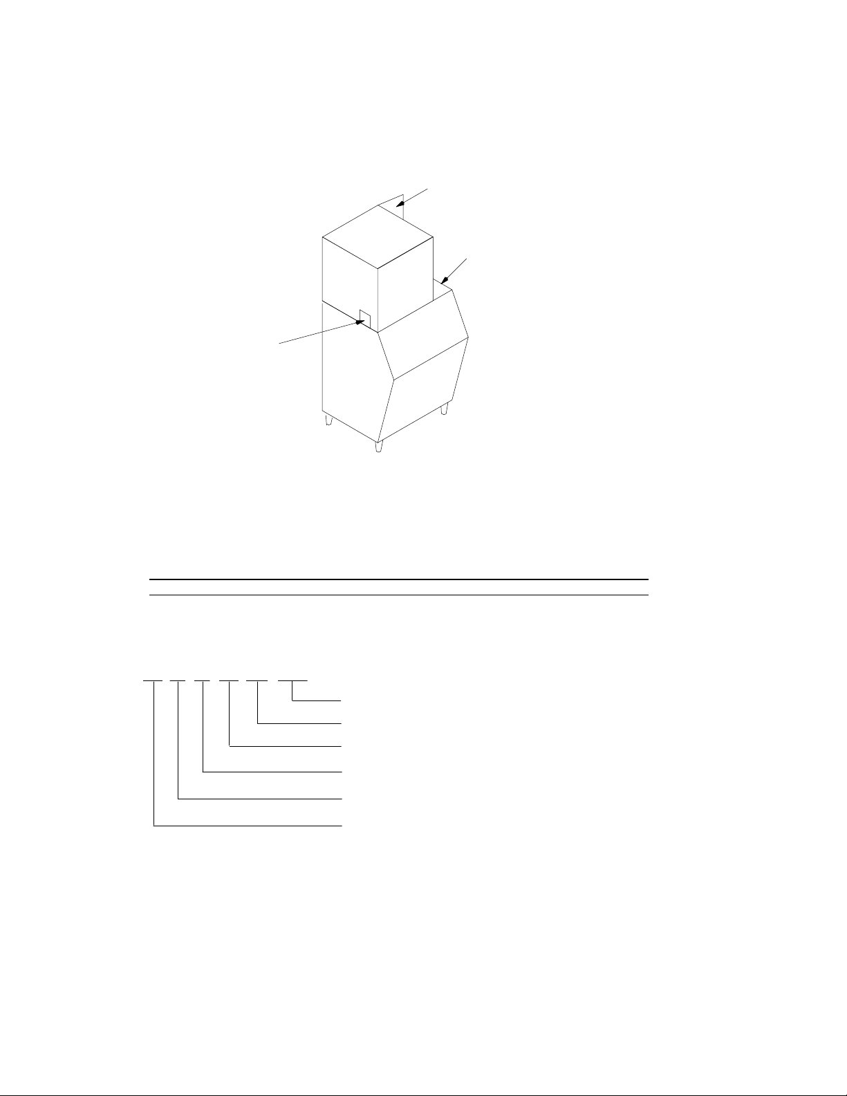
MODEL AND SERIAL LOCATION
XTREME ICE MACHINE
Condenser Discharge Air
Deflector (as required)*
Bin Adapter (as required)*
Model/Serial
Number Location
FIGURE 1
*Bin adapters and condenser discharge air deflector may be equipped depending on your location or the
size of the storage bin.
Record the model number and the serial number of your ice equipment. These numbers are required
when requesting information from your local dealer/distributor/service company.
Model Number – Date Installed –
Serial Number – Purchased From -
SERIAL NUMBER EXPLANATION
63 A 01 01 BC 101
Sequential Number
Product Code (PC) – Ice Maker
Week of Manufacture – First week of the year
Year of Manufacture – 2001
Control Code (Revision Level)
Manufacturing Location – Mason City
SPECIFICATIONS
The following table contains equipment specification information for the Ice Machines.
Xtreme Ice Training Manual
TP00952
October 17, 2005 3
Model
XAC
322/330
XWC
322/330
XAC
522/530
XWC
522/530
XRC
522/530
XAC
630
XWC
630
XRC
630
XAC
830
UNIT
Volts
Phase
Hertz
No. Wires
115
1
60
2+Ground
230
1
60
2+Ground
MIN. CIRCUIT
Amps
20 15 20
MAX. FUSE
SIZE. Amps 20 15 20
REFRIGERANT
Type
Weight (oz)
Weight (g)
R404a
19
539
R404a
15
426
R404a
25
709
R404a
23
652
R404a
135
3,827
R404
a
40
1,134
R404
a
35
992
R404
a
170
4,820
R404
a
42
1,191
COMPRESSOR
LRA
RLA
58.8
9.2
68
11.9
40.6
6.9
60
8.9
CONDENSER
FAN MOTOR
Amps
Watts
1.7
50
NA
NA
1.7
50
NA
NA
NA
NA
1.1
75
NA
NA
NA
NA
1.1
75
WATER PUMP
Amps
Watts
0.7
20
Model
XWC
830
XRC
830
XAC
1030
XWC
1030
XRC
1030
XAC
1230
XWC
1230
XRC
1230
XWC
1230
E50
XAC
1444
E50
UNIT
Volts
Phase
Hertz
No. Wires
230
1
60
2+Ground
220
1
50
2+Ground
MIN. CIRCUIT
Amps
20
30
MAX. FUSE
SIZE Amps 20
30
REFRIGERANT
Type
Weight (oz)
Weight (g)
R404a
33
936
R404a
170
4,820
R404a
42
1,191
R404a
33
936
R404a
170
4,820
R404
a
49
1,191
R404
a
45
1,276
R404
a
210
5,954
R404
a
45
1,276
R404
a
67
1,900
COMPRESSOR
LRA
RLA
60
8.9
90
12
96
13.5
84
12.2
76
13.0
96
21.5
CONDENSER
FAN MOTOR
Amps
Watts
NA
NA
NA
NA
1.2 (2)
60 (2)
NA
NA
NA
NA
1.2
(2)
60 (2)
NA
NA
NA
NA
NA
NA
0.6
1/15h
p
WATER PUMP
Amps
Watts
0.7
20

Xtreme Ice Training Manual
TP00952
October 17, 2005
4
Model
XAC
1444
XWC
1444
XRC
1444
XAC
1844
XWC
1844
XRC
1844
XAC
322
E50
XAC 330
E50
XAC 522
E50
XAC 530
E50
UNIT
Volts
Phase
Hertz
No. Wires
230
1
60
2+Ground
220
1
50
2+Ground
MIN. CIRCUIT
Amps
30
30
10 15
MAX. FUSE
SIZE Amps 30
40
10 15
REFRIGERANT
Type
Weight (oz)
Weight (g)
R404
a
67
1900
R404
a
36
1021
R404
a
250
7088
R404
a
R404
a
R404
a
R404
a
19
539
R404a
19
539
R404a
25
709
R404a
25
709
COMPRESSOR
LRA
RLA
108
17
179
28
26.3
3.9
31
5.6
CONDENSER
FAN MOTOR
Amps
Watts
0.6
1/15
HP
NA
NA
NA
NA
2.7
1/3H
P
NA
NA
NA
NA
1.75
50
1.75
50
1.75
50
1.75
50
WATER PUMP
Amps
Watts
0.7
20
Model
XAC
630
E50
XAC
830
E50
XAC
1030
E50
XAC
1230
E50
XAC
1844
3PH
XWC
1844
3PH
XRC
1844
3PH
XWC
522/530
E60
XWC
522
E50
XAC
522/530
E60
UNIT
Volts
Phase
Hertz
No. Wires
220
1
50
2+Ground
230
3
60
3+Ground
230
1
60
2+Ground
220
1
50
2+Ground
230
1
60
2+Ground
MIN. CIRCUIT
Amps
15 20
20 15 15
MAX. FUSE
SIZE Amps
15 20 20 15 15
REFRIGERANT
Type
Weight (oz)
Weight (g)
R404
a
40
1134
R404
a
42
1191
R404
a
42
1191
R404
a
49
1389
R404
a
R404
a
R404
a
R404a
23
652
R404a
26
737
COMPRESSOR
LRA
RLA
34
5.5
54
8.1
83
11.3
76
13
135
17
34
6.8
31
5.6
34
6.8
CONDENSER
FAN MOTOR
Amps
Watts
1.1
75
1.1
75
1.2
(2)
60(2)
1.2
(2)
60(2)
2.7
1/3H
P
NA
NA
NA
NA
NA
NA
NA
NA
1.2
60
WATER PUMP
Amps
Watts
0.7
20
NA= Not applicable
Important: All product supply voltage specifications are –5%/+10% for proper
component operation.

Xtreme Ice Training Manual
TP00952
October 17, 2005 5
GENERAL
FREIGHT DAMAGE CLAIMS PROCEDURE
The deliverer of your equipment (freight company, distributor or dealer) is responsible for loss or damage
of your shipment. All claims must be filed with the deliverer of your equipment. Please follow the steps
below to determine if your shipment is satisfactory or if a claim must be filed:
1. Check the number of products delivered against the number of products listed on the delivery re-
ceipt. Should the totals not match, have the driver note all errors on both copies and both you and
the driver sign and date said notation.
2. Inspect all cartons for visible damage. Open and inspect as required before the driver leaves and
have him or her note any damage on the receipts. All damaged claims must be inspected within 15
days of delivery. Notify your carrier immediately if concealed damage is found after delivery.
3. Should concealed damage be found when product is unpacked, retain the packing material and the
product and request an inspection from the deliverer.
4. All claims for loss or damage should be filed at once. Delays in filing will reduce the chance of
achieving a satisfactory resolution to the claim.
TECHNICAL SPECIFICATIONS
Cube Size: 5/8”W X 7/8”H X 7/8”D
Ambient Temperature: 50_F/10_C – 100_F/38_C
Water Temperature: 50_F/10_C – 90_F/32_C
Water Pressure: 20–80 psi
Maximum Fuse Size: See Nameplate
Circuit Amp.: See Nameplate
Refrigerant Type: R–404a
Refrigerant Charge: See Nameplate
Xtreme Ice Training Manual
TP00952
October 17, 2005
6
INSTALLATION INSTRUCTIONS
Installation and start up of the equipment should be performed by the distributor or the dealer’s profes-
sional staff.
LOCATION OF EQUIPMENT
For maximum performance the location should be away from heat sources such as ovens, direct sunlight,
hot air discharge, etc.
To reduce cost of maintenance and loss of efficiency, avoid placing air-cooled equipment in areas where
grease, flour and other airborne contaminants are present. Allow a minimum of 6I (15.24 cm.) clearance
at the rear and right side for proper air circulation. Restricted air circulation will affect the efficiency and
required maintenance of the product.
IMPORTANT: Never operate your equipment in room temperature below 50_F (10_) or above
100_F (38_C). Should the location of your product ever be exposed to freezing temperatures, it
must be shut down and winterized.
EQUIPMENT SET-UP
The following steps refer to the set-up of the ice bin and the cuber:
1. Remove the bin from its carton, place it on its back and install the legs and drain flange (if applica-
ble) into the bottom of the bin. Bins must be installed on legs or sealed to the floor with RTV-732
sealant.
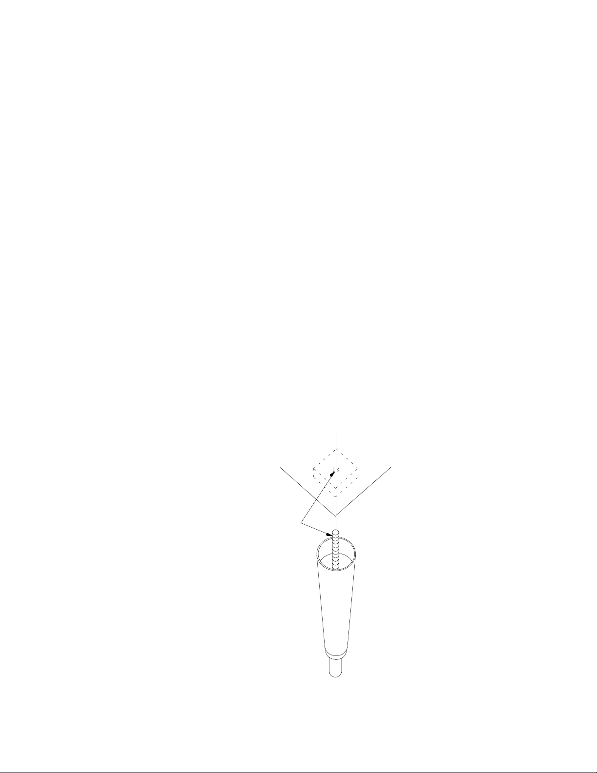
2. Set the bin up on its legs. Place the bin in its final location and level it with the adjustable feet in the
legs. (See Figure 2).
NOTE: It is critical that the unit be level to ensure adequate ice production.
3. Unpack the cuber from its carton, and set in place on the bin and adjust as required. Leave all pan-
els on the cuber until it is set in place on the dispenser or bin.
4. Remove all internal packing from the cuber. Remove tape from evaporator curtain.
THREAD LEVELING
LEG INTO BASE
FIGURE 2
NOTE: Bin adapter and condenser air baffles may be required in certain installations.
Xtreme Ice Training Manual
TP00952
October 17, 2005 7
DISPENSER INSTALLATION
1. Order the proper cuber/dispenser adaptor kit. This package include gasket material, a hold-down
bracket, and bin stat kit (contact service provider for more information).
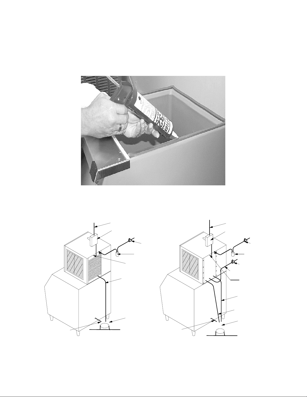
2. RTV applications (See Figure 3). If the ice bin is full, new ice will not be able to drop. Instead it
blocks the evaporator curtain open and no additional ice is made. This new ice may start to melt and
the resulting liquid can leak out of the joint between the ice maker and bin. To prevent this problem,
seal the joint with food grade silicon sealant.
FIGURE 3
3. Install Bin stat, Part No. 631500074 (See Bin Stat Kit Instructions).
Figure 4 is an example of a typical electrical and plumbing connection.
AIR-COOLED MODELS
WATER-COOLED MODELS
Electrical Service Line
Manual Disconnect
Switch
STRAIN RELIEF
MUST BE USED
Water Filter
Shut-Off Valve
Dump
Valve
Drain
Tube
Bin Drain
Tube
*Air Gap 4”
“minimum”
Electrical Service Line
Manual Disconnect Switch
Shut-Off Valve
Water Filter
Shut-Off Valve
Condenser Water Inlet
Dump Valve
Drain Tube
*Air Gap 4”
“minimum”
Bin Drain
Tube
Condenser Water
Drain Tube
Strain Relief
must be used
Floor Drain
Floor Drain
FIGURE 4
* An air gap of at least twice the diameter of the water supply inlet plus a minimum of 1” (25 mm) must
exist between the floor drain and drain tube.
NOTE: Leave all panels on the cuber until it is in place on the bin.

Xtreme Ice Training Manual
TP00952
October 17, 2005
8
PLUMBING CONNECTIONS
1. All plumbing lines and connections must conform to local and national plumbing codes.
2. Line shut-off valves must be located in supply water lines for cuber and condenser if product is wa-
ter-cooled. Water supply to water-cooled condenser must include a stand-pipe to prevent “water
hammer”.
3. Should your local water supply quality require the installation of a water filter system, consult your
local distributor or dealer for proper size required.
4. Water supply pressure must not be lower than 20 PSI (1.37 BAR), nor should it exceed 80 PSI (5.52
BAR).
NOTE: Water filters larger than 5 microns do not give proper protection.
NOTE: Bin and cuber drain lines must never be connected together and must be vented.
NOTE: Always flush inlet water lines 1–2 minutes before connecting to Ice Maker.
ELECTRICAL
1. All wiring and connections must conform to national and local electrical codes.
2. Wire size and circuit protection must conform to specifications and cuber must be on a separate
electrical circuit.
3. Strain relief connectors must be used at the junction box of the control box and the cuber.
4. Cuber must be grounded by the control box ground screw or other method for intentional safety
grounding that meets code requirements.
5. A manual disconnect in a convenient location to the cuber must be installed.
NOTE: See Remote Condensers, Install Instructions.
NOTE: All HP-62 (R404A) ice machines have a voltage range of –5%, +10% from the serial plate
rating.
INSTALLATION CHECK POINTS
1. Has bin and cuber been leveled and sanitized?
2. Does electrical and plumbing meet code requirements?
3. If water-cooled, are inlet and drain connections to condenser correct?
4. Are drain lines separate and vented?
5. Is there a 6I clearance on the right and back side for proper air circulation?
6. Does the water curtain move freely? Does the inlet solenoid valve shut off incoming water to
the water pan?
7. Has the unit been properly sealed to the bin or dispenser?
NOTE: A 6” top clearance will improve service accessibility.
START UP AND CHECK OUT
Start Up Sequence
1. Check all connections.
2. Turn on the main power switch. The red LED will flash 6 times then remain on for 4 seconds.
3. The unit will go through a 45 second hot gas defrost to remove any ice that might be on the
evaporator.
4. There will be approximately a (45) second evaporator pre–chill, then the water pump will start,
and the freeze cycle begins.

Xtreme Ice Training Manual
TP00952
October 17, 2005 9
Preventative Maintenance Sequence
The installation is not complete until you are sure the owner-operator understands the cuber operation
and his or her responsibility of preventative maintenance.
Does the owner-operator know:
1.
Location of electrical disconnect switch and water shut-off valves?
2. How to start and/or shut down the product, clean and sanitize it?
3. Bin full operation and reset operation of high pressure cutout (water-cooled and remote
products and 500 series (Air Cooled)?
4. How to clean the condenser and fan blade?
5. Whom to call for product information and/or service?
NOTE: CONDENSER SENSOR USED ONLY ON A/C UNITS. 1.8K ohm RESISTER USED ONLY ON
W/C & R/C UNITS.
Xtreme Ice Training Manual
TP00952
October 17, 2005
10
CLEANING PROCEDURES
Approved ice machine cleaners by brand names:
S Calgon Nickel Safe (green color only)
NOTE: Failure to use approved products will void the warranty.
CAUTION: Ice machine cleaners are acidic-based chemicals. Before beginning any
cleaning of the cuber, the ice in the storage bin or dispenser must be removed.
WARNING: When using any chemical, rubber gloves and eye protection should be worn.
Cleaning Procedure if there is ice on the evaporator plate.
1. Turn the power switch on.
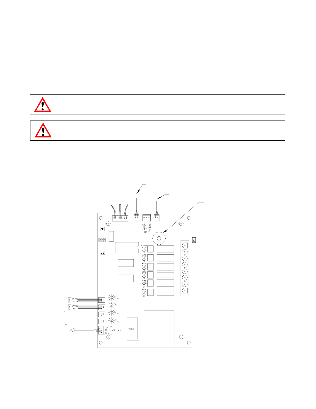
2. Press and hold the Harvest button to start a 4 minute defrost cycle. (Button is located on the control
board see Figure 5).
FILL VALVE
WATER PRESSURE LINE
POWER
NEUTRAL
HOT GAS
WATER PUMP
COMPRESSOR
FAN MOTOR (AIR COOLED)
DUPM VALVE
RH EVAP
SWITCH
LH EVAP
SWITCH
STOCKING
CABLE PLUG
NOTE: CONDENSER SENSOR USED ONLY ON A/C UNITS.
1.8K ohm RESISTER USED ONLY ON W/C AND R/C UNITS.
(WHITE LEAD)
CONDENSER SENSOR SEE NOTE
(BLACK LEAD)
WATER TEMP SENSOR
ERROR
DELAY
CLEAN
HARVEST
UNIT
SELECTION
SWITCH
S3–1
BIN
SWITCHES
TRANSFORMER
#1
#3
#2
#4
#5
#6
#7
BRIDGE
THICKNESS
POT
S3–2
OFF
3 2 1
OFF
ON
ON
MICRO
PROCESSOR
(MANUFACTURING DATE)
3643001
FIGURE 5
NOTE: Condenser sensor used only on A/C units. 1.8k resistor used only in W/C and R/C units.
Single evaporator units must have the proximity connected in the top connection.
Xtreme Ice Training Manual
TP00952
October 17, 2005 11
PREP – CLEANING PROCEDURE
Use ice machine cleaner on a coarse-surface cloth material (such as terry cloth) and wipe down the in-
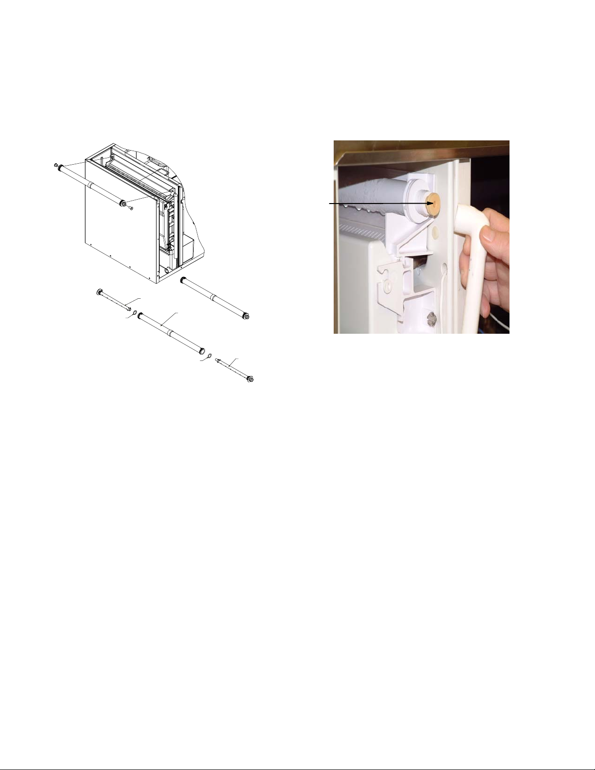
side wall of the evaporator area, the water pan, the water curtain and the plastic water deflector. If the
water distributor tube has heavy scale build-up, remove and soak it in full-strength nickel safe ice ma-
chine cleaner (or exchange the tube and clean the scaled tube at a later date) (See Figure 6).
SCALE 1:2
INNER WATER DISTRIBUTOR
INNER WATER DISTRIBUTOR BARB
”O” RING
”O” RING
WATER DIST. ASSEMBLY
All single evaporator units use a water restrictor
Water Restrictor
to regulate the water flow pattern over the evaporator.
FIGURE 6
Cleaning the Water System and Evaporator
1. Turn the power switch to “OFF”.
2. Remove all ice from the storage bin.
3. Remove the water curtain(s), pour 1/2 oz. of ice machine cleaner down the top of the evaporator.
The cleaner will drain into the water pan.
4. Remove the water tube, clean with brush and “Calgon Nickel Safe” ice machine cleaner.
5. Return the water curtain(s) to their proper operating positions.
6. Add “Calgon Nickel Safe” ice machine cleaner directly into the water pan (green only):
S 5 oz. for the 300’s,
S 8 oz. for the 500’s, 600’s, and 800’s,
S 12 oz. for the Dual Evaporator, and
S 16 oz. for the Quad.
7. Turn the power switch to “ON” , allow the compressor to start, and depress the clean button two
times on the front of the electrical box.
8. The unit will run through a fifteen (15) minute cleaning cycle, which includes 3 rinse cycles.
9. Once the cleaning cycle finishes, the error LED will flash 8 times.
10. When the clean cycle is complete, turn the power switch to “OFF” for five (5) seconds, then to “ON”.
The unit will return to normal operating mode. Discard the first batch of ice produced.
NOTE: Ice machines should only be cleaned when needed, not by a timed schedule of every 60
days, etc. Should your ice machine require cleaning more than twice a year, consult your distrib-
utor or dealer about proper water treatment.

Xtreme Ice Training Manual
TP00952
October 17, 2005
12
SANITIZING THE WATER SYSTEM AND THE EVAPORATOR
NOTE: To be performed only after cleaning the ice machine:
1. Turn the power switch to “OFF”.
2. Add 1/4 ounce (7.08 g) sodium hypochlorite solution (common liquid laundry bleach) to the water
pan. You may also use a commercial sanitizer such as Calgon Ice Machine Sanitizer following the
directions on the product label.
3. Turn the Cuber power switch “ON” allowing the compressor to start. Depress the clean button two
times on the control board. The unit will run through a 15 minute sanitizing cycle.
4. Once the sanitizing cycle is complete, the error LED will flash 8 times. Turn the power switch to
“OFF” for 5 seconds and then turn to “ON”. Discard the first batch of ice produced.
5. To sanitize the bin and other surface areas, use 1 ounce of liquid bleach per gallon of water and wipe
all areas with the solution. Or use a commercial sanitizer.
6. Cleaning and sanitizing are now complete. Cuber may be returned to normal service.
Xtreme Ice Training Manual
TP00952
October 17, 2005 13
OPERATIONS
CAUTION: WHEN REPLACING THIS BOARD, BE SURE THE DIP SWITCH SETTINGS ARE IN THE
PROPER POSITION FOR YOUR UNIT.
UNIT SELECTION
1. The unit selection dip switches tell the microprocessor the correct water level difference for harvest
and the number of proximity switch circuits to monitor.
2. The unit selection dip switches are a series of 3 switches that can be placed in either the ON or OFF
position.
3. The following list shows the dip switch settings for each model:
NOTE: The unit selection switches are preset at the factory to the correct model. Use the chart
below if the control is replaced.
Model Switch 1 Switch 2 Switch 3 Proximity Switch Circuits
300 OFF OFF OFF 1
500 ON OFF OFF 1
600/800/1000 OFF ON OFF 1
1200 ON ON OFF 2
1400/1800 OFF OFF ON 2
NORMAL OPERATIONS
1. Start up sequence.
2. Secondary start up.
3. Dump cycle.
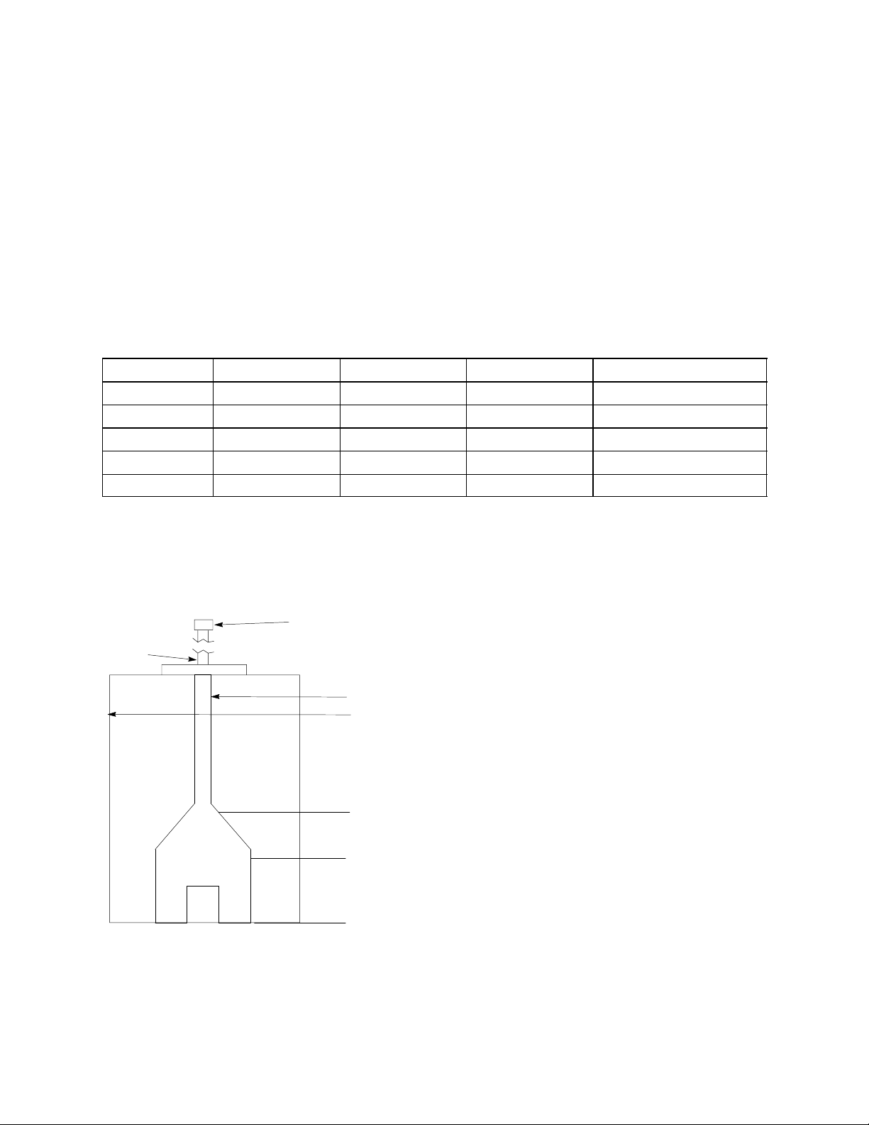
4. Water fill cycle (See Figure 7).
DEFROST LEVEL (B)
DUMP LEVEL (C)
PRESSURE
LINE
PRESSURE TRANSDUCER
1. During fill, water level rises to (A).
2. During Ice Product cycle, water level
lowers to (B). Defrost cycle initiated.
3. During Defrost cycle, water level low-
ers to (C).
4. When Proximity Switches closes, the fill
valve opens and water level rises to (A).
START LEVEL (A)
WATER PAN
FIGURE 7
5. Prechill cycle.
6. Freeze cycle.
7. Harvest cycle.
8. Continue with the dump cycle.
9. Fan cycles on condenser temperature (88–100_F).
10. The safety features are monitored during the proper cycle.
 Loading...