


CCM0322
Table of contents
 Loading...
CCM and CCU Series Installation, Start-up and Maintenance Manual Manual Number 631806051
Nordic Ice Maker
Model CCM and CCU Series
Installation, Start-up and Maintenance Manual
IMI CORNELIUS INC.
www.cornelius.com
Publication Number: 631806051
Revision Date: April 16, 2010
Revision: F
Visit the IMI Cornelius web site at www.cornelius.com
for all your Literature needs.

*

Forward
Page i
How To Use This Manual
Cornelius provides this manual as an aid to the service technician in installation and maintenance of the
CCM and CCU Series cube ice machines. Do not attempt to perform installation, start-up or maintenance unless
you have read and fully understand this manual.
If at any time you encounter conditions that are not addressed in this manual, please contact the Cornelius
Technical Service Department at:
E-Mail: tech.service@Cornelius.com
Website :
www.cornelius.com
Telephone Number
800-238-3600 All Departments
Any Service communication must include:
• Model Number
• Serial number
• A detailed explanation of the problem
Keep this manual for future reference.
The Cornelius CCM and CCU Series Service Parts Manuals are available separately.
Cornelius icemakers and dispensers are not approved for outdoor installation.
WARNING: Always disconnect electrical power and shut off water supply whenever maintenance or
repairs are performed on the ice machine and related equipment.
CAUTION: Always wear protective eyewear whenever maintenance or repairs are performed on the ice
machine and related equipment.

Table of Contents
Page ii
Foreward Page i
Table of Contents Page ii
Freight Claim Procedure Page iii
Model Number and Serial Number Format Page 1
Installation Guidelines Page 2
Remote Condenser Guidelines Page 4
Electrical and Plumbing Requirements Page 6
How the Machine Works Page 13
Start-Up Procedure Page 14
General Maintenance Page 16
Cleaning Procedure Page 17
Cabinet Care Page 18
Winterizing Procedure Page 19
Maintenance Record Page 20

Freight Claim Procedure
Page iii
Freight Claims Important!
Inspect Promptly
This merchandise has been carefully inspected and packed in accordance with the carrier’s packing specifications.
Responsibility for safe delivery has been assumed by the carrier. If loss or damage occurs, you as the consignee must
file a claim with the carrier and hold the container for carrier’s inspection.
Visible Loss or Damage
Any external evidence of loss or damage must be fully described and noted on your freight bill or express receipt and
signed by the carrier’s agent. The claim should be filed on a form available from the carrier.
Concealed Loss or Damage
If loss or damage does not appear until merchandise has been unpacked, make a written request for inspection by the
carrier within 15 days of the delivery date. Then file a claim on a form from the carrier.
File Claim Without Delay
Do Not Return Damaged Merchandise to Cornelius
Model and Serial Number Format
Page 1
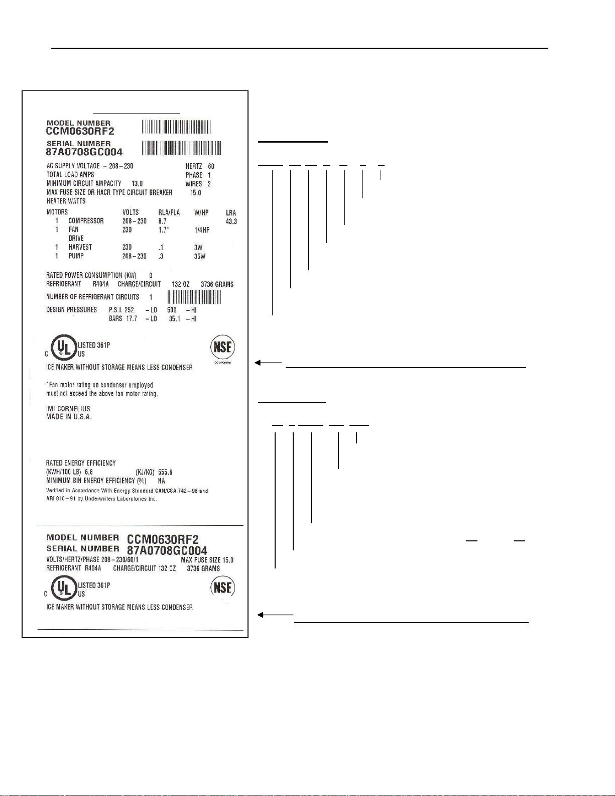
Model and Serial Number Format
The serial number format and machine specifics are detailed on the
data plate.
Model Number
CCM 06 30 A H 1 2
Engineering Rev Level
Voltage:1=115V, 2=230V, 3=230V 3ph 5=50Hz.
Cube Size: H=Half Cube, F=Full Cube
Condenser Type: A=Air, W=Water, R=Remote
Cabinet Width (in inches)
Approximate Production X 100 in 24 hours 70°F Air / 50°F Water
Series: Cornelius Cuber Modular (U=Undercounter)
Large data plate will be placed on the back of the unit.
Serial Number
87
A 0708 GC 004
Sequencial Serial Number
Product Line
GC=Cuber
GB=Remote Condenser
GA= Dispenser
Date Code, Year Month format. (2007
August 08)
Revision Level (Internal)
Manufacturing Facility
Small data plate will be placed by the service valves
.
Sam
p
le Data Plate
Note: The date code will change monthly and yearly to reflect the date of manufacture.

Installation Guidelines
Page 2
Installation Guidelines
For proper operation of the Cornelius ice machine, the following installation guidelines mu st be followed. Failure to do
so may result in loss of production capacity, premature part failures, and may void all warranties.
Reference the installation parameters prior to installing the machine:
Ambient Operating Temperatures
Minimum Operating Temperature: 50°F (10°C)
Maximum Operating Temperature 100°F (38°C), 110°F (43°C) on 50 Hz. Models.
Note: Cornelius icemakers and dispensers are not approved for outdoor installation.
Incoming Water Supply (See Electrical and Plumbing Diagrams for line sizing)
Minimum incoming water temperature: 40°F (4.5°C)
Maximum incoming water temperature: 100°F (38°C)
Minimum incoming water pressure: 20 psi (1.4 bar)
Maximum incoming water pressure: 60 psi (4.1 bar)
Note: If water pressure exceeds 60 psi (4.1 bar), a water pressure regulator must be installed.
Drains
All drain lines must be installed per local codes. Flexible tubing is not recommended. Route bin drain, purge drain and
water condenser drain individually to a floor drain. The use of condensate pumps for draining water is not
recommended by Cornelius. Cornelius assumes no responsibility for improperly installed equipment.
Note: The purge drain fitting is plastic; DO NOT apply heat to the purge drain area; DO NOT over tighten.
Water Filtration
A water filter system should be installed with the ice machine.
Clearance Requirements
Self-contained air cooled ice machines must have a minimum of 6 inches (15cm) of clearance at the rear, top, and
sides of the ice machine for proper air circulation.
Stacking
If the ice machines are to be stacked, refer to the instructions in the stacking kit. Cornelius does not endorse stacking
air-cooled ice machines.
Dispenser Application
A thermostatic bin control kit should be installed if the CCM Series ice machine is placed on a dispenser. A bin top
may or may not be required. (Exception is the CHD22 and CHD30 Series Dispenser)
Electrical Specifications
Refer to the serial plate at the rear of the ice machine to make sure proper voltage and circuit breaker size have been
supplied. Make sure the machine is on a dedicated circuit. European installations require that the electrical supply
fixed wiring must be provided with a disconnect means having a separation of at least 3mm in all poles. The ice
machines are provided
without an electrical cord set and are designed and agency approved to be permanently
connected.
The 115 volt Undercounter series ice makers are supplied with an electrical cord, all other ice makers will
need to be installed and wired per local electrical codes.
CAUTION: Electrical connection must be made or a cord installed by a
qualified electrician or there is danger of an
electrical fire.
Adjustments
Level the machine within 1/8 inch in all directions.
Check the bin control for proper adjustment.
Check the water in the water trough for proper level.
Check the ice bridge for proper thickness.
Check the water regulating valve adjustment if water cooled.
Installation Guidelines
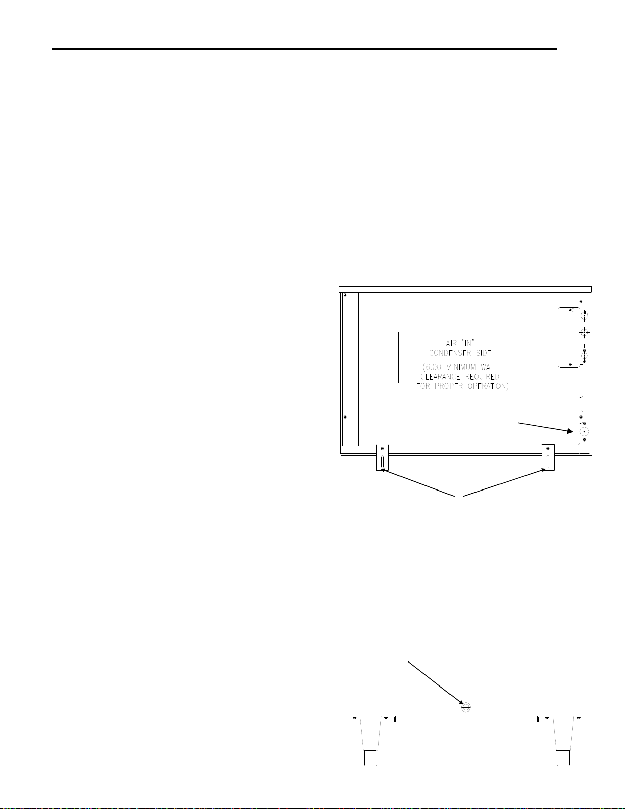
Secure the machine on top of the bin or dispenser.
Attach the ice machine to the bin with the mounting straps provided with the bin or dispenser. Insure that the back of
the ice machine is flush with the back of the bin. Proper functioning of the bin door requires the bin door, when it is
opened, to be in a stable position.
If the ice machine is too far forward on the bin, the opened door may not be stable, resulting in an unexpected closing
of the bin door. If the ice machine is to be mounted on a bin or dispenser other than a Cornelius, refer to the
manufacturers instructions for machine mounting. Cornelius will not be responsible for damage or injury that results
from unexpected closing of the bin door as a result of the ice machine being too far forward on the bin.
If the ice machine is to be stacked on top of another ice machine, a stacking kit will need to be installed. Refer to the
installation instructions included with the stacking kit.
Important!
A water filtration system should be installed with all ice machines. Check the filter manufacturer's instructions for
proper installation.
All water supply lines must be installed per local codes.
Use 1/4 inch O.D. minimum on air cooled machines. On
water cooled machines 3/8 inch O.D. minimum tubing
must be run to the condenser. The water supply for the
float can “T” off from the condenser line using 1/4 inch
O.D. minimum tubing. Make 2 coils of extra tubing so that
the machine can be pulled away from the wall if service is
needed.
Page 3
All drain lines must be installed per local codes. The
purge drain should be a minimum of 5/8 inch O.D. tubing.
The condenser drain on water cooled units should be 3/8
inch O.D. minimum. The drain line fittings on Cornelius
bins are 3/4 FPT. The bin drain should be a minimum of
3/4 inch O.D. Cold water drains should be insulated to
prevent condensation from forming.
IMPORTANT!
Attach the ice machine to the bin or
dispenser with the provided
mounting hardware. Insure the back
of the ice machine is flush with the
back of the bin.
Warning!
Do not apply heat directly to the
back of bin as damage may occur
to plastic parts.
Warning! Do not over-tighten as
damage may occur to plastic
parts
Warning!
Do not apply heat directly to the back of bin as damage
may occur to plastic parts.
Do not over-tighten the purge drain fitting as damage
may occur to plastic parts.
Connect power supply to the terminal block in the control
box or at the rear junction box if equipped.
Ensure the machine is level within 1/8 inch in all
directions.
Remove any shipping or packaging material.
If the machine has a remote condenser, reference the
Remote Condenser Installation Guidelines.
Once the machine has been installed, follow the
start-up procedures.
Loading...