


®
INTELLICARB
Training Manual
Release Date: April 29, 2004
Publication Number: TP01071
Revision Date: NA
Revision: A
Visit the IMI Cornelius web site at www.cornelius.com for all your Literature needs.

INTELLICARB TRAINING MANUAL
The products, technical information, and instructions contained in this manual are subject to change without notice. These instructions are not intended to cover all details or variations of the equipment, nor to provide for every possible contingency in the installation, operation or maintenance of this equipment. This manual assumes that the person(s) working on the equipment have been trained and are skilled in working with electrical, plumbing, pneumatic, and mechanical equipment. It is assumed that appropriate safety precautions are taken and that all local safety and construction requirements are being met, in addition to the information contained in this manual.
To inquire about current revisions of this and other documentation or for assistance with any Cornelius product contact:
www.cornelius.com
800-238-3600
Trademarks and copyrights:
Aurora, Cornelius, Decade, Hydro Boost, Sitco, Spirit, UF-1, Vanguard, Venture, Olympus, and Vista are registered trademarks of IMI Cornelius Inc.
Optifill trademark is pending.
This document contains proprietary information and it may not be reproduced in any way without permission from Cornelius.
Printed in U.S.A.
Copyright © 2004, All Rights Reserved, IMI Cornelius Inc.

InelliCarb Training Manual
TABLE OF CONTENTS
Introduction . . . . . . . . . . . . . . . . . . . . . . . . . . . . . . . . . . . . . . . . . . . . . . . . . . . . . . . . . . .1
Unit Description . . . . . . . . . . . . . . . . . . . . . . . . . . . . . . . . . . . . . . . . . . . . . . . . . . . . . .1
Theory of Operation . . . . . . . . . . . . . . . . . . . . . . . . . . . . . . . . . . . . . . . . . . . . . . . . . .1
Description . . . . . . . . . . . . . . . . . . . . . . . . . . . . . . . . . . . . . . . . . . . . . . . . . . . . . . . . .1
Specifications . . . . . . . . . . . . . . . . . . . . . . . . . . . . . . . . . . . . . . . . . . . . . . . . . . . . . . .2
Requirements . . . . . . . . . . . . . . . . . . . . . . . . . . . . . . . . . . . . . . . . . . . . . . . . . . . . . . .2
Delivery Inspection and Unpacking . . . . . . . . . . . . . . . . . . . . . . . . . . . . . . . . . . . . . . .2
Installation . . . . . . . . . . . . . . . . . . . . . . . . . . . . . . . . . . . . . . . . . . . . . . . . . . . . . . . . . .3
Drains . . . . . . . . . . . . . . . . . . . . . . . . . . . . . . . . . . . . . . . . . . . . . . . . . . . . . . . . . .4
Cornelius IntelliCarb Carbonator Assembly . . . . . . . . . . . . . . . . . . . . . . . . . . . . . . . .4
Carbonator Time Out Reset Switch . . . . . . . . . . . . . . . . . . . . . . . . . . . . . . . . . . .4
Carbonator Relief Valve Locations . . . . . . . . . . . . . . . . . . . . . . . . . . . . . . . . . . . .5
Mechanical Section . . . . . . . . . . . . . . . . . . . . . . . . . . . . . . . . . . . . . . . . . . . . . . . . . . . . .8
Gate Restrictor Plate . . . . . . . . . . . . . . . . . . . . . . . . . . . . . . . . . . . . . . . . . . . . . . . . . .8
Adjustment . . . . . . . . . . . . . . . . . . . . . . . . . . . . . . . . . . . . . . . . . . . . . . . . . . . . . .8
Ice Diverter Kit 02394 . . . . . . . . . . . . . . . . . . . . . . . . . . . . . . . . . . . . . . . . . . . . . . . . .9
Removal and Replacement of Agitators . . . . . . . . . . . . . . . . . . . . . . . . . . . . . . . . . .10
To Remove Agitators For Cleaning (300 shown) . . . . . . . . . . . . . . . . . . . . . . . .10
Post-Mix Valve Section . . . . . . . . . . . . . . . . . . . . . . . . . . . . . . . . . . . . . . . . . . . . . . . . .11
Set-up Instructions . . . . . . . . . . . . . . . . . . . . . . . . . . . . . . . . . . . . . . . . . . . . . . . . . .11
Dimensions & Capacities . . . . . . . . . . . . . . . . . . . . . . . . . . . . . . . . . . . . . . . . . .11
System Details . . . . . . . . . . . . . . . . . . . . . . . . . . . . . . . . . . . . . . . . . . . . . . . . . . . . .11
Water . . . . . . . . . . . . . . . . . . . . . . . . . . . . . . . . . . . . . . . . . . . . . . . . . . . . . . . . . .11
Water Quality . . . . . . . . . . . . . . . . . . . . . . . . . . . . . . . . . . . . . . . . . . . . . . . .11
Water Flow . . . . . . . . . . . . . . . . . . . . . . . . . . . . . . . . . . . . . . . . . . . . . . . . . .11
Adjusting Flow Rates . . . . . . . . . . . . . . . . . . . . . . . . . . . . . . . . . . . . . . . . . .13
Calculating Flow Rates . . . . . . . . . . . . . . . . . . . . . . . . . . . . . . . . . . . . . . . . .13
Syrup/Concentrate . . . . . . . . . . . . . . . . . . . . . . . . . . . . . . . . . . . . . . . . . . . . . . .13
Setting Ratios . . . . . . . . . . . . . . . . . . . . . . . . . . . . . . . . . . . . . . . . . . . . . . . . . . .14
Shurflo . . . . . . . . . . . . . . . . . . . . . . . . . . . . . . . . . . . . . . . . . . . . . . . . . . . . . . . . . . . . . .15
Shurflow Overview . . . . . . . . . . . . . . . . . . . . . . . . . . . . . . . . . . . . . . . . . . . . . . . . . .15
Shurflow Installation . . . . . . . . . . . . . . . . . . . . . . . . . . . . . . . . . . . . . . . . . . . . . . . . .16
Start-up Procedure . . . . . . . . . . . . . . . . . . . . . . . . . . . . . . . . . . . . . . . . . . . . . . . . . .16
Plumbing . . . . . . . . . . . . . . . . . . . . . . . . . . . . . . . . . . . . . . . . . . . . . . . . . . . . . . . . . . . . |
17 |
Typical Installation . . . . . . . . . . . . . . . . . . . . . . . . . . . . . . . . . . . . . . . . . . . . . . . . . . |
17 |
Plumbing Layout . . . . . . . . . . . . . . . . . . . . . . . . . . . . . . . . . . . . . . . . . . . . . . . . . . . . |
18 |
Flow Diagram 1xx (Six Flavor Model) . . . . . . . . . . . . . . . . . . . . . . . . . . . . . . . . . . . . |
19 |
Flow Diagram 1XX (Eight Flavor Models) . . . . . . . . . . . . . . . . . . . . . . . . . . . . . . . . . |
20 |
Flow Diagram 2xx (Eight Flavor Models) . . . . . . . . . . . . . . . . . . . . . . . . . . . . . . . . . |
21 |
Flow Diagram 2xx (Ten Flavor Models)) . . . . . . . . . . . . . . . . . . . . . . . . . . . . . . . . . . |
22 |
Flow Diagram 300 (Twelve Flavor Models) . . . . . . . . . . . . . . . . . . . . . . . . . . . . . . . |
23 |
© 2004, IMI Cornelius Inc. |
- i - |
Publication Number: TP01071 |

IntelliCarb Training Manual
Electrical Section . . . . . . . . . . . . . . . . . . . . . . . . . . . . . . . . . . . . . . . . . . . . . . . . . . . . . 24
Carbonator Wiring Diagram . . . . . . . . . . . . . . . . . . . . . . . . . . . . . . . . . . . . . . . . . . . 25 Wiring Diagram 1xx (120V) . . . . . . . . . . . . . . . . . . . . . . . . . . . . . . . . . . . . . . . . . . . 26 Schematic 1xx . . . . . . . . . . . . . . . . . . . . . . . . . . . . . . . . . . . . . . . . . . . . . . . . . . . . . 27 Wiring Diagram 2xx (120V Model) . . . . . . . . . . . . . . . . . . . . . . . . . . . . . . . . . . . . . . 28 Wiring Diagram 2xx (220/240V Models) . . . . . . . . . . . . . . . . . . . . . . . . . . . . . . . . . . 29 Wiring Diagram 2xx (220/240V Models) . . . . . . . . . . . . . . . . . . . . . . . . . . . . . . . . . . 30 Wiring Diagram 300 (220/240V Models) . . . . . . . . . . . . . . . . . . . . . . . . . . . . . . . . . 31 Wiring Diagram 300 (220/240V Models) . . . . . . . . . . . . . . . . . . . . . . . . . . . . . . . . . 32 Schematic 300 (120V Models) . . . . . . . . . . . . . . . . . . . . . . . . . . . . . . . . . . . . . . . . . 33 Schematic 300 (220/240V Models) . . . . . . . . . . . . . . . . . . . . . . . . . . . . . . . . . . . . . 34
Troubleshooting . . . . . . . . . . . . . . . . . . . . . . . . . . . . . . . . . . . . . . . . . . . . . . . . . . . . . . 35
SHURflow Troubleshooting . . . . . . . . . . . . . . . . . . . . . . . . . . . . . . . . . . . . . . . . . . . 35 Pumping Capability . . . . . . . . . . . . . . . . . . . . . . . . . . . . . . . . . . . . . . . . . . . . . . . 35 Pumps in Series for Long Distances . . . . . . . . . . . . . . . . . . . . . . . . . . . . . . . . . 36 Pump Sanitizing / Winterizing . . . . . . . . . . . . . . . . . . . . . . . . . . . . . . . . . . . . . . . 36 Pump Troubleshooting . . . . . . . . . . . . . . . . . . . . . . . . . . . . . . . . . . . . . . . . . . . . 37
DOES NOT OPERATE / GAS APPLIED / DISPENSER VALVE OPEN . . . 37 OPERATES BUT WILL NOT PRIME / DISPENSER VALVE OPEN . . . . . . 37 DOES NOT ACHIEVE SOLD-OUT WITH EMPTY B-I-B . . . . . . . . . . . . . . . 37 AIR IN INLET AND/OR OUTLET TUBING . . . . . . . . . . . . . . . . . . . . . . . . . . 37 STROKES WITH DISPENSER VALVE CLOSED . . . . . . . . . . . . . . . . . . . . 37 FLUID FROM EXHAUST OR VISIBLE WITHIN GAS INLET TUBING . . . . . 37 GAS BLOWING FROM EXHAUST CONTINUOUSLY . . . . . . . . . . . . . . . . . 37
Dispenser Troubleshooting . . . . . . . . . . . . . . . . . . . . . . . . . . . . . . . . . . . . . . . . . . . 38 Valve Troubleshooting . . . . . . . . . . . . . . . . . . . . . . . . . . . . . . . . . . . . . . . . . . . . . . . 39 Excess Foam . . . . . . . . . . . . . . . . . . . . . . . . . . . . . . . . . . . . . . . . . . . . . . . . . . . 39 Off Taste . . . . . . . . . . . . . . . . . . . . . . . . . . . . . . . . . . . . . . . . . . . . . . . . . . . . . . . 40 Valve Stuck Open . . . . . . . . . . . . . . . . . . . . . . . . . . . . . . . . . . . . . . . . . . . . . . . . 41 No Product . . . . . . . . . . . . . . . . . . . . . . . . . . . . . . . . . . . . . . . . . . . . . . . . . . . . . 42 Carbonator Troubleshooting . . . . . . . . . . . . . . . . . . . . . . . . . . . . . . . . . . . . . . . . . . . 43 Solid State Carbonator Level Control . . . . . . . . . . . . . . . . . . . . . . . . . . . . . . . . . 43 Test Solid State Level Control . . . . . . . . . . . . . . . . . . . . . . . . . . . . . . . . . . . 43
Publication Number: TP01071 |
- ii - |
© 2004, IMI Cornelius Inc. |

InelliCarb Training Manual
INTRODUCTION
UNIT DESCRIPTION
•Built-in cold carbonator produces bottle-quality drinks every time
•No seasonal CO2 adjustments required for changes in water temperature
•A complete system for simplified installation
•Reduces service frequency and lowers equipment life cost
•Generates increased beverage sales and greater consumer satisfaction
•Illuminated merchandiser delivers unique, high impact marketing message
•Ice used to cool cold plate kept separate from ice dispensed into cups
•One piece ABS thermoformed plastic ice storage hopper. Durabide™ design provides durability and ensures all ice in the hopper is dispensable
•Unit readily accepts top mount cubers with manual ice fill capability
THEORY OF OPERATION
The rate of CO2 solubility increases with cold water. IntelliCarb System provides pre–chilled cold water from the cold plate and mix with CO2 in the carbonator tank. The water is introduced into the tank with a high volume 125gph Procon pump and high torque motor.
The amount of carbonated water reserve is controlled by a probe mounted in the tank. The probe is called a “liquid level probe”. The liquid level probe senses the water level in the tank. Probe controls the pump “ON” and “OFF” cycle through the electronic board called “liquid level board”.
NOTE: The probe works on a 5 M.V. D.C. current that continually reverses direction to prevent probe corrosion.
DESCRIPTION
The “Enduro IntelliCarb” series of ice dispensers solves your ice and beverage service needs in a sanitary, space saving, economical way. Designed to be automatically filled with ice from a top mounted ice machine or manually filled with ice from any remote ice-making source, these dispensers will dispense cubes (up to 1-1/4 inch in size), cubelets, and hard-chipped or cracked ice. In addition, the units include beverage faucets, a cold plate, an internal carbonator tank and an external pump for the carbonator, and are designed to be supplied direct from syrup tanks with no additional cooling required.
IMPORTANT: For dispensing compressed or extruded style ice, an Ice Diverter Kit must be installed on the dispenser, see FIGURE 13 on page 9.
© 2004, IMI Cornelius Inc. |
- 1 - |
Publication Number: TP01071 |

IntelliCarb Training Manual
SPECIFICATIONS
|
ED150 |
ED175 |
ED200 |
ED250 |
|
|
B=(Beverage) |
B=(Beverage) |
B=(Beverage) |
B=(Beverage) |
|
Model |
C=(Coldplate) |
C=(Coldplate) |
C=(Coldplate) |
C=(Coldplate) |
|
H=(Internal |
H=(Internal |
H=(Internal |
H=(Internal |
||
Descriptions: |
|||||
Carb) |
Carb) |
Carb) |
Carb) |
||
|
|||||
|
Z=(No DripTray) |
Z=(No DripTray) |
Z=(No DripTray) |
Z=(No DripTray) |
|
Ice Storage: |
150 Pounds |
175 Pounds |
200 Pounds |
250 Pounds |
|
Maximum |
6 |
8 |
10 |
10 |
|
Number of |
|
|
|
|
|
Faucets |
|
|
|
|
|
Available: |
|
|
|
|
|
Built-in Cold |
Yes |
Yes |
Yes |
Yes |
|
Plate: |
|
|
|
|
|
|
$PSV 7RWDO 8QLW 'UDZ |
120/1/60, 3.5 Amps Total Unit Draw |
|||
|
|
|
230/1/50, 2.0 Amps Total Unit Draw |
||
Electrical:
Dimensions:
CO2 Operating
Pressure
Width 22”
Deep 30--11/16”
High 35--5/8”
Z--Models
Width 22”
Deep 23--1/16”
High 35--5/8”
75--psig (max)
Outlet should be within 6 feet of dispenser.
Width 24.5” |
Width 22” |
Width 24.5” |
Deep 30--11/16” |
Deep 30–11/16” |
Deep 30–11/16” |
High 35--5/8” |
High 35–5/8” |
High 39–5/8” |
|
Z–Models |
|
Width 24--1/2” |
Width 22” |
Width 24–1/2” |
Deep 23--1/16” |
Deep 23–1/16” |
Deep 23–1/16” |
High 35--5/8” |
High 35–5/8” |
High 39–5/8” |
75--psig (max) |
75–psig (max) |
75–psig (max) |
ED300
B=(Beverage)
C=(Coldplate)
H=(Internal
Carb)
Z=(No DripTray)
300 Pounds
12
Yes
120/1/60, 4.0 Amps Total Unit Draw 230/1/50, 3.0 Amps Total Unit Draw
Width 44–3/8”
Deep 31–1/2”
High 37”
Z–Models
Width 44–3/8”
Deep 23–1/16”
High 37”
75–psig (max)
REQUIREMENTS
•Weight: counter must be level and able to support 450 lbs.
•Environment: Indoor installation only
•Temperature: 40 to 100oF
•CO2: 75 psi at unit
•Syrup: 60 psi., 0.70 -- 0.75 ounces per sec. (0.6 gpm) at unit
•Water: 60 psi at pump
•Electrical: See name plate
DELIVERY INSPECTION AND UNPACKING
Upon delivery inspect the unit for damage or irregularities and immediately report problems to the delivering carrier and file a claim with that carrier.
•Open loose parts packages and inspect parts.
Part No. |
Description |
Qty. |
710000030 |
Pump and Motor Assy |
1 |
70970 |
4”Legs |
4 |
70750 |
Clamps |
2 |
620702201 |
Brush |
1 |
51774 |
Drain Pan Drain Line |
1 |
50335 |
Drain Line Insulation |
1 |
|
)LWWLQJ 6RF [ )SW |
1 |
|
)LWWLQJ 0SW [ µ%DUE |
1 |
Publication Number: TP01071 |
- 2 - |
© 2004, IMI Cornelius Inc. |

InelliCarb Training Manual
INSTALLATION
1.Locate the dispenser indoors on a level counter top.
A.LEG OPTION
Unpack the four (4) legs and install them into the threaded holes provided in the bottom of the unit. The installer must provide flexibility in the product and utility supply to permit shifting the position of the dispenser sufficiently to clean the area beneath it.
B.COUNTER MOUNTING
If counter mounted the ice drink dispenser must be sealed to the counter. The template drawing indicates where openings can be cut in the counter. Locate the desired position for the dispenser, then mark the outline dimensions on the counter using the template drawings. Cut openings in counter.
Apply a continuous bead of NSF International (NSF) silastic sealant (Dow 732 or equal) approximately 1/4--inch inside of the unit outline dimensions and around all openings. Then, position the unit on the counter within the outline dimensions. All excess sealant must be wiped away immediately.
2.The beverage tubes, drain tube and power cord are routed through the large opening in the bottom of the unit. See the mounting template for locating the required clearance opening in the counter for these utility lines.
3.Drip tray assembly: Route the drain tube to an open drain with the end of the tube above the “flood” level of the drain. Use the tubing, fittings, clamps, and insulation provided with the Dispenser to assemble the drain. The completed drain line must pitch continuously downward and contain no “traps” or improper drainage will result. Must have a 4 inch air gap between drain line and drain.
NOTE: This equipment must be installed with adequate backflow protection to comply with federal, state, and local codes.
NOTE: IMI Cornelius Inc. recommends that a water shutoff valve and water filter be installed in the plain water inlet supply line. A Cornelius Water Filter (P/N 313860000) and QUICK DISCONNECT SET (P/N 313867000) are recommended.
CAUTION: Check the minimum flow rate and the maximum pressure of the plain water inlet supply line. MINUMUM FLOW RATE MUST BE AT LEAST 125--GALLONS PER HOUR. If flow rate is less than 125- -gallons per hour, starving of the carbonator water pump will occur. Starving will damage the water pump and could cause the carbonator to time out. INCOMING PLAIN WATER INLET SUPPLY LINE WATER TO PUMP PRESSURE MUST REMAIN A MINIMUM OF 10--PSI BELOW THE CARBONATOR CO2 OPERATING PRESSURE. (Example: Carbonator CO2 operating pressure is 75--PSI and the maximum water pressure can be no more than 65--psi, etc.). Water over pressure (higher than CO2 operating pressure) can cause carbonator flooding, malfunction, and leakage through the carbonator relief valve. If water is exceeding maximum pressure specifications, a Water Pressure Regulator Kit (P/N 310150000) or equivalent must be installed in the plain water inlet supply line. If fitting connector is not available, water line must be 1/2” or 3/4” diameter with a shut off valve within 6 feet of the dispenser.
4.Locate the carbonator pump assembly and connect probe wires from Ice/Drink Unit and pump. Connect inlet water to pump and pump outlet to Ice/Drink Unit using 3/8--inch food--grade tubing.
NOTE: Locate carbonator assembly within 6 feet of the dispenser. Do not lengthen the control board harness.
5.Connect the beverage system product tubes as indicated in applicable Plumbing Flow Diagram, see page 19. This work should be done by a qualified service person.
NOTE: Water pressure for non carbonated beverages must be 60 P.S.I. minimum.
NOTE: See applicable Flow Diagram or Decal on the lower front of the unit for the location of syrup and water connections.
6.Clean the hopper interior.
7.Connect the two power cords to a 120 volt, 60 cycle, 3-wire grounded receptacle. For 220--240 Volt International Units, a 3--wire power cord is provided. An adapter plug for the particular country will need to be provided by the Installer.
© 2004, IMI Cornelius Inc. |
- 3 - |
Publication Number: TP01071 |
IntelliCarb Training Manual
Drains
Use a 1 - 1/2” rigid pipe (e.g. ABS on P.V.C.) this is to prevent kinking or collapsing. Make sure to leave a 4 inch air gap between the drain line and the floor drain.
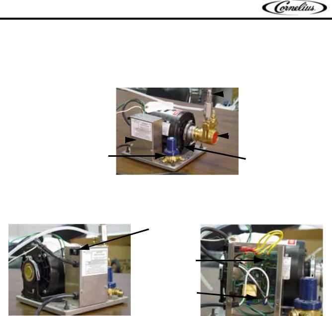
CORNELIUS INTELLICARB CARBONATOR ASSEMBLY
1.Ice Drink / Drop-In Carbonator Pump & Motor Unit
 Vent to Atmosphere Check Valve
 125 G.P.H. ProCon Water Pump
Liquid Level Control Box 
Preset CO2 Regulator (75P.S.I.)
High Torque Pump Motor
FIGURE 1
Carbonator Time Out Reset Switch
The board can be set to turn the carbonator off after three or seven minutes of continuos time. The feature can also be disabled. See the carbonator instruction in this manual.
Carbonator
Time Out Reset
Switch
Time Out
Selector Pins
Liquid Level
Control Board
FIGURE 2 |
FIGURE 3 |
1.Locate carbonator assembly below dispenser no more than 6 feet away. Important: Make sure there is clearance for the liquid level control reset switch on the side of the control box to avoid accidentally tripping the switch. The control board has an internal timer to prevent the pump motor from running continuously. In the event of a water supply interruption or malfunction of the water level probe and/or motor relay circuit. If there is a time-out event, make necessary repairs to what caused the time out, then depress and release the reset switch to put the control board back in service. By moving a jumper on the control you can select either a 7 minute or 3 minute time out or this feature can also be disabled.
A.Hook-up a 3/8 ID water supply line 125 G.P.H. minimum (60 psig. max.) to pump inlet. Minimum flowing pressure is 30 psig. Important: Tap for non-carb water supply must be upstream of pump inlet. Do not tap in the pump outlet.
B.Hook-up a 3/8 (.375 ID) CO2 supply line (100 psig.) to the inlet of the pre-set CO2 regulator (75 psig.) on the Pump & Motor base. Note: If using a bulk CO2 tank as supply, tank pressure regulator must be set to 100-105 psig. The regulator on the bulk tank should be a secondary.
Publication Number: TP01071 |
- 4 - |
© 2004, IMI Cornelius Inc. |

InelliCarb Training Manual
C.Initial start-up procedure for carbonated water system: Turn on the CO2 supply to the carbonator tank, vent air from carbonator tank by pulling the tank relief valve. Turn on water supply to the pump. Connect electrical power to the pump and motor unit. Bleed the air out of the system by energizing a beverage valve until carbonated water is flowing from the valve.
NOTE:If the carbonator Pump and Motor does not cycle (turn on and off) properly, check that the probe harness connector and ground lead are secured to the carbonator tank connection points.
D.If service is required on Ice Drink units, it will be necessary to lower the beverage valve panel to gain access to the probe and ground connection. Remove the lower front panel (2 screws) from the cabinet and the ice chute cover (“snap” fit). Remove the 6 screws that secure the beverage panel to the cabinet. The panel can now be moved downward due to the flexibility of the beverage tubing to expose the carbonator tank connections.
Carbonator Relief Valve Locations
The carbonator tank is located behind the splash panel, on the right side of the dispenser. You will need to pull the relief valves to purge air from the system after the CO2 supply has been hooked up. Failure to do this will cause low carbonation volume and popping of the relief valves.
Agitator
Motor
Relief |
|
Carbonator |
Valve Ring |
|
|
|
Tank |
|
|
|
Carbonator
Tank Relief
Valve
FIGURE 6 |
FIGURE 7 |
2.Dispenser
Ice Drink Model ED175BCH (Lower Front Panel Removed)
Insulated Cold Plate
Cover & Carbonator
Tank Assembly
Total Flex Manifold
(with insulation)
 Total Flex Manifold Cold Plate Inlets (insulation removed)
(3/8 Barb)
Carb. Tank Liquid |
|
|
Carb Tank CO2 |
||
|
|
|
|
||
|
|
Supply Line |
|||
Level Probe Harness |
|
|
|
||
|
|
|
|
|
|
FIGURE 8
© 2004, IMI Cornelius Inc. |
- 5 - |
Publication Number: TP01071 |

IntelliCarb Training Manual
Ice Drink Model ED150/175/300 Coldplate Cover |
Ice Drink Model ED200/250 Coldplate Cover |
||||||
|
|
|
|
|
|
|
|
|
|
|
|
|
|
|
|
|
|
|
|
|
|
|
|
|
|
|
|
|
|
|
|
Liquid Level Probe |
CO2 |
Check Valve with Ground Stud |
In-line CO2 Check Valve |
Probe |
Ground Plate/Stud |
|
|||||
|
FIGURE 9 |
FIGURE 10 |
|
||
3.Total Flex System for Ice Drink Models ED150/175/200/250/300
Total Flex Manifold (Insulation Removed)
Water Line |
|
|
|
|
|
Plugs |
Retainer Clip 
Manifold Block
FIGURE 11
Total Flex is a system of water manifold blocks located at the front of the cold plate, adjacent to the cold plate inlets, for easy switch over of carbonated / non-carbonated beverage drinks. The right hand manifold block is for the beverage valves located to the right side of the ice chute, and the left block is for the left bank of valves. Each beverage valve on the dispenser can be set up for either carbonated or non-car- bonated drinks. Refer to the unit’s plumbing diagram for the factory carbonated / non-carbonated valve locations. The procedure for switching carbonated / non-carbonated water lines on a beverage valve is as follows:
A.Shut off the water supply to the dispenser. Depressurize and drain both the carbonated and noncarbonated water circuits.
B.Remove the retainer clip (2 screws) from the manifold block. Switch the plug and water line fitting to their respective carbonated / non-carbonated outlet locations on the block.
C.Replace the retainer clip. Turn on the water supply and energize the “switched” valve(s). Check for water leaks.
4.Important: Route the dispenser’s drain line to an open drain with the end of the tube above the flood level of the drain. The drain line must pitch downward and contain no “traps”.
5.Connect both the carbonator pump and motor unit and the dispenser to a grounded electrical supply outlet.
Publication Number: TP01071 |
- 6 - |
© 2004, IMI Cornelius Inc. |
IntelliCarb Training Manual
6.Check list for proper “finished” drink carbonation:
A.Fill ice storage hopper with ice.
B.Water supply must be from a continuous source (no tank supply).
C.Use only filtered water.
D.Supply water line to the carbonator pump must be a minimum of .375 ID.
E.Syrup supply lines must be a minimum of .265 ID.
F.Water inlet pressure range: 45-60 max. static psig. with a minimum flowing pressure of 30 psig.
G.Syrup CO2 secondary regulator pressure set to 60 psig.
H.CO2 supply must be high quality, food grade.
I.Purge all water, carb-water, and product lines of air before brixing valves.
J.Important: Brix valves with cold product. Allow at least 15-20 minutes for ice to cool down the coldplate on initial start-up before brixing the valves.
K.Dispense at least (2) 12 oz. drinks before taking a carbonation level reading.
L.Carbonation tester thermometer must read 32-33oF. for accurate carb-level reading. Store tester in ice water bath during use.
M.Hold cup at valve nozzle for drink to be tested. Pour drink slowly down the side wall into the carbtester to avoid agitation during pouring. Press vent valve once on carb-tester after tightening lid.
N.Shake carb-tester in vertical motion until peak pressure reading is obtained. Use Pepsi chart for carbonation level reading.
NOTE: Carbonator troubleshooting procedure located on page 43.
© 2004, IMI Cornelius Inc. |
- 7 - |
Publication Number: TP01071 |

IntelliCarb Training Manual
MECHANICAL SECTION
GATE RESTRICTOR PLATE
NOTE: Disconnect power to dispenser before installing, removing, or adjusting restrictor.
ADJUSTMENT
INSTALL PLATE
ON STUDS AS
SHOWN
FIGURE 12
Adjustment
This plate may be adjusted as shown to reduce or increase the dispensing rate of ice, especially desirable when using glasses or other containers with small openings. Adjustment can be made by sliding up or down with nuts loosened, to obtain the desired amount of restriction.
Publication Number: TP01071 |
- 8 - |
© 2004, IMI Cornelius Inc. |
IntelliCarb Training Manual
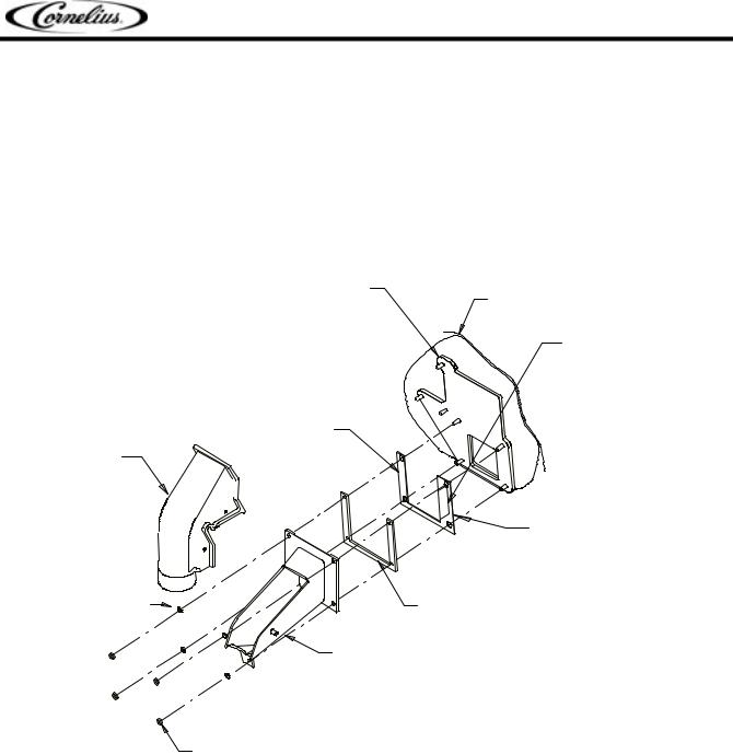
ICE DIVERTER KIT 02394
NOTE: For dispensing Scotsman, Wilshire, and Hoshizaki compressed ice cubes:
1.Disconnect power to dispenser.
2.Remove Merchandiser from dispenser.
3.Remove ice chute and discard gate restrictor.
4.Install ice diverter on gate mounting plate as shown below.
5.Apply RTV to back surface of ice diverter, to seal to gate mounting plate.
6.Reinstall gasket and ice chute.
7.Reinstall merchandiser and energize unit.
G AT E MO U NT ING P L AT E
S T O R A G E HO P P E R
F L A NG E E X T E NDS
INT O S T O R A G E HO P -
P E R T HR O U G H G AT E
O P E NING
IC E DIV E R T E R
IC E C HU T E
C O V E R
|
A P P LY R T V T O |
|
T HIS S U R FA C E T O |
|
S E A L T O HO P P E R |
|
G AT E MO U NT ING |
10 - 32 WA S HE R |
P L AT E |
G A S K E T |
|
|
IC E C HU T E |
10 - 32 NU T
FIGURE 13
© 2004, IMI Cornelius Inc. |
- 9 - |
Publication Number: TP01071 |

IntelliCarb Training Manual
REMOVAL AND REPLACEMENT OF AGITATORS
To Remove Agitators For Cleaning (300 shown)
NOTE: All other models have only one agitation Assembly.
LEFT HAND |
RIGHT HAND AGITATOR |
|
WITH HOLE IN UPRIGHT |
||
AGITATOR |
||
|
||
|
O–RING |
COUNTERCLOCKWISE
CLOCKWISE
ROTATION |
ROTATION |
FRONT (VALVE SIDE) VIEW FROM TOP OF DISPENSER
FIGURE 14
1.Lift agitator and disc from unit.
2.Remove O-Ring starting at notch. Warm the O-Ring with water to ease removal.
3.Lift the plastic agitator disc off of the stainless-steel agitator.
4.Replace by reversing steps.
NOTE: Refer to Sanitize Procedure in the Owners Instruction for complete cleaning and sanitizing instructions.
Publication Number: TP01071 |
- 10 - |
© 2004, IMI Cornelius Inc. |
|
IntelliCarb Training Manual |
POST-MIX VALVE SECTION |
|
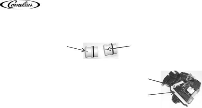
SET-UP INSTRUCTIONS |
|
Concentrate valve sleeve |
Syrup valve sleeve |
has only one hole |
has six holes |
FIGURE 15 |
|
A side water lever kit can be added to a valve allowing for |
|
dispensing of water without syrup or concentrate. The side |
Mounting |
water lever can be added to either a carbonated drink valve |
screw |
or a noncarbonated drink valve. |
|
Post-mix valves control: |
Water |
|
lever |
• the ON–OFF of syrup and water,
• the flow rates of syrup and water,
FIGURE 16
• the mixing of the two ingredients as they pour into the cup, and
• in some instances - dispensed portion.
Dimensions & Capacities
Fast Flow ............................................................................................................... |
1 ½ to 3 oz./sec. |
UFB-1 ......................................................................................................................... |
2 to 4 oz./sec. |
Ultra Flow .............................................................................................................. |
3 to 4 ½ oz./sec. |
Operational temperature range: ......................................................... |
10°C (50°F) to 43°C (110° F) |
Voltage requirements:................................................................................ |
22 to 27 VAC (50/60 Hz) |
Transformer (electronic valves) ........................................................................................ |
80 VA min. |
Operating Pressure (flowing)............................................................................... |
syrup = 20 psi min. |
............................................................................................................................. |
water = 35 psi min. |
Concentrates and juices that contain particulates must be dispensed from a juice valve.
A slanted drip tray is necessary when using an Optifill valve.
SYSTEM DETAILS
Water
Water Quality
Water quality issues have an affect on dispensing valves. Chloramine, a combination of chlorine and ammonia is responsible for some degradation of rubber components. Chloramine is used in many U. S. water supplies. Its affects can be minimized by installing and maintaining a water filtration system.
Ultra pure water affects the sensitivity of the Optifill™ valve. Because ultra pure water has less mineral content, it reduces the conductivity of the water keeping the circuit open and overfilling the beverage container.
Water Flow
The size of the orifice in the piston varies depending on whether the piston is used for syrup or water, and whether it is high flow or ultra flow valve.
© 2004, IMI Cornelius Inc. |
- 11 - |
Publication Number: TP01071 |
 Loading...