


Comtech EF Data is an
AS9100 Rev B / ISO9001:2000 Registered Company
MDX420 SkyWire™
Satellite Network Gateway
Installation and Operation Manual
IMPORTANT NOTE: The information in this document supersedes all previously published information for this product. This manual is subject to change without notice.
Part Number MN-MDX420 |
Revision 6 |

Comtech EF Data is an
AS9100 Rev B / ISO9001:2000 Registered Company
MDX420 SkyWire™
Satellite Network Gateway
Installation and Operation Manual
Part Number MN-MDX420
Revision 6
Copyright © 2013 Comtech EF Data. All rights reserved. Printed in the USA.
Comtech EF Data, 2114 West 7th Street, Tempe, Arizona 85281 USA, 480.333.2200, FAX: 480.333.2161
Blank Page

MDX420 SkyWire Satellite Network Gateway |
Revision 6 |
Table of Contents |
MN-MDX420 |
|
|
Table of Contents |
|
About this Manual |
....................................................................................................................................... |
i |
|
Warranty Policy.......................................................................................................................................... |
|
v |
|
Product Support......................................................................................................................................... |
|
vi |
|
CHAPTER 1. ................................................................................... |
INTRODUCTION |
1–1 |
|
1.1 |
SkyWire Product .......................................................................................................Overview |
1–1 |
|
1.2 |
MDX420 Simple ...................................................................................................Block Design |
1–2 |
|
1.3 |
Understanding ................................................................................................................TDMA |
1–3 |
|
1.4 |
SkyWire TDMA ..........................................................................................................Network |
1–4 |
|
1.4.1 |
SkyWire ............................................................................................Network Share Group |
1–5 |
|
1.4.2 |
SkyWire ........................................................................Eight Site Mesh Network Example |
1–6 |
|
1.4.3 |
SkyWire ....................................................................Sixteen Site Mesh Network Example |
1–7 |
|
1.4.4 |
SkyWire ..................................................Eight Site Hub / Spoke (Star) Network Example |
1–8 |
|
1.5 |
IP Ethernet .................................................................................................................Data Port |
1–9 |
|
1.5.1 |
Quality .......................................................................................................of Service (QoS) |
1–9 |
|
1.5.2 |
CRC Control ....................................................................Satellite Packet Error Checking |
1–10 |
|
CHAPTER 2. ............. |
SKYWIRE HARDWARE & SOFTWARE CONFIGURATIONS |
2–1 |
|
2.1 |
SkyWire Features ..................................................................................................and Options |
2–1 |
|
2.2 |
Standard Configuration ............................................................................................................. |
2–1 |
|
2.3 |
Hardware Options ...................................................................................................................... |
2–1 |
|
2.4 |
Software Options......................................................................................................................... |
2–2 |
|
2.5 |
Hardware Field ..........................................................................................................Upgrades |
2–2 |
|
CHAPTER 3. ..................................................... |
UNPACKING AND INSTALLATION |
3–1 |
|
3.1 |
Installation ..........................................................................................................Requirements |
3–1 |
|
3.2 |
Unpacking.................................................................................................................................... |
|
3–2 |
3.3 |
AC Power Requirements............................................................................................................ |
3–2 |
|
3.4 |
Installation ........................................................................................................Considerations |
3–2 |
|
iii

MDX420 SkyWire Satellite Network Gateway |
Revision 6 |
Table of Contents |
MN-MDX420 |
CHAPTER 4. |
FRONT & REAR PANEL INTERFACES .............................................. |
4–1 |
||
4.1 |
|
Front Panel .................................................................................................................................. |
4–1 |
|
4.1.1 |
Front Panel Status Indicators ................................................................................................ |
4–1 |
||
4.2 |
Front Panel LED Status Indicators........................................................................................... |
4–2 |
||
4.3 |
|
Rear Panel Connections.............................................................................................................. |
4–3 |
|
4.3.1 |
Compact Flash (J5) ............................................................................................................... |
4–3 |
||
4.3.2 |
Power Input Modules............................................................................................................ |
4–3 |
||
|
4.3.2.1 AC Power Input Module ................................................................................................... |
4–3 |
||
|
4.3.2.2 DC Power Input (Optional)............................................................................................... |
4–3 |
||
4.3.3 |
Chassis Connections (Standard)............................................................................................ |
4–3 |
||
|
4.3.3.1 |
TX IF (J9) ......................................................................................................................... |
4–3 |
|
|
4.3.3.2 |
RX IF (J8) ......................................................................................................................... |
4–4 |
|
|
4.3.3.3 |
Alarm (J6) ......................................................................................................................... |
4–4 |
|
|
4.3.3.4 |
Service Port (J7)................................................................................................................ |
4–5 |
|
|
4.3.3.5 Control Port, Ethernet 10/100 (J1 & J2) ........................................................................... |
4–5 |
||
|
4.3.3.6 Data Port, Ethernet 10/100/1000 (J3 & J4)....................................................................... |
4–6 |
||
CHAPTER 5. |
CONFIGURING THE MDX420 SKYWIRE ............................................ |
5–1 |
||
5.1 |
Initial Setup of the MDX420 SkyWire ...................................................................................... |
5–1 |
||
5.2 |
|
Function Accessibility................................................................................................................. |
5–1 |
|
5.3 |
|
Initial Configuration Check ....................................................................................................... |
5–1 |
|
5.3.1 |
Standard Factory Configuration Settings.............................................................................. |
5–2 |
||
5.4 |
|
Initial Power-Up.......................................................................................................................... |
5–2 |
|
5.5 |
|
Monitor and Control................................................................................................................... |
5–2 |
|
5.5.1 |
Ethernet Control Port Factory Defaults: ............................................................................... |
5–2 |
||
5.5.2 |
Control Port (J1 & J2)........................................................................................................... |
5–2 |
||
5.5.3 |
Service Port (J7).................................................................................................................... |
5–2 |
||
CHAPTER 6. |
TERMINAL SCREENS.......................................................................... |
6–1 |
||
6.1 |
Service Port User Interface ........................................................................................................ |
6–1 |
||
6.2 |
Description of the Service Port (J7)........................................................................................... |
6–1 |
||
6.2.1 |
Terminal Screens .................................................................................................................. |
6–1 |
||
6.2.2 |
Reserved................................................................................................................................ |
6–2 |
||
6.2.3 |
Connecting to the Service Port (J7) ...................................................................................... |
6–2 |
||
6.2.4 |
Terminal Screens .................................................................................................................. |
6–3 |
||
|
6.2.4.1 |
Main Menu........................................................................................................................ |
6–3 |
|
|
6.2.4.2 Demodulator Menu Options and Parameters .................................................................... |
6–4 |
||
|
6.2.4.3 Modulator Menu Options and Parameters ........................................................................ |
6–6 |
||
|
6.2.4.4 |
System Controls ................................................................................................................ |
6–8 |
|
iv

MDX420 SkyWire Satellite Network Gateway |
Revision 6 |
Table of Contents |
MN-MDX420 |
6.2.4.5 |
Demodulator Alarms......................................................................................................... |
6–9 |
|
6.2.4.6 |
Modulator Alarms ........................................................................................................... |
6–10 |
|
6.2.4.7 |
System Alarms ................................................................................................................ |
6–11 |
|
6.2.4.8 |
TCP/IP/FTP Controls...................................................................................................... |
6–12 |
|
6.2.4.9 |
SNMP V1 |
& V2 Controls ............................................................................................... |
6–14 |
6.2.4.10 |
SNMP V3 |
Controls ......................................................................................................... |
6–15 |
6.2.4.11 |
Event Log |
........................................................................................................................ |
6–17 |
6.2.4.12 |
Test Diagnostics.............................................................................................................. |
6–18 |
|
CHAPTER 7. |
|
SKYWIRE CONTROLLER GUI ............................................................. |
7–1 |
|
7.1 |
SkyWire Controller Graphical User Interface (GUI).............................................................. |
7–1 |
||
7.2 |
Installing the SkyWire Controller GUI .................................................................................... |
7–2 |
||
7.3 |
Connect and Login...................................................................................................................... |
7–4 |
||
7.3.1 |
Destination Configuration Screen......................................................................................... |
7–4 |
||
7.3.1.1 |
Destination Name.............................................................................................................. |
7–5 |
||
7.3.1.2 |
IP Address......................................................................................................................... |
7–5 |
||
7.3.1.3 |
SNMP Version .................................................................................................................. |
7–5 |
||
|
7.3.1.3.1 |
SNMPV2 ........................................................................................................................... |
7–5 |
|
|
7.3.1.3.2 |
SNMPV3 ........................................................................................................................... |
7–6 |
|
7.3.1.4 |
Polling Interval.................................................................................................................. |
7–6 |
||
7.4 |
SkyWire Controller Configure Tab .......................................................................................... |
7–7 |
||
7.4.1 |
Configure Satellite Link........................................................................................................ |
7–8 |
||
7.4.1.1 |
Modulator Configuration .................................................................................................. |
7–8 |
||
7.4.1.2 |
Demodulator Configuration .............................................................................................. |
7–9 |
||
7.4.1.3 BUC and LNB Configuration ......................................................................................... |
7–10 |
|||
7.4.1.4 |
AUPC Configuration....................................................................................................... |
7–11 |
||
7.4.2 |
Configure Terrestrial Interface............................................................................................ |
7–14 |
||
7.4.3 |
Configure Network Configuration ...................................................................................... |
7–16 |
||
7.4.4 |
Configure Test and Diagnostics.......................................................................................... |
7–19 |
||
7.4.5 |
Configure System Configuration ........................................................................................ |
7–20 |
||
7.4.6 |
Configure Alarms................................................................................................................ |
7–22 |
||
7.4.7 |
Configure Share Group ....................................................................................................... |
7–25 |
||
7.4.8 |
Configure TCP/IP Settings.................................................................................................. |
7–28 |
||
7.5 |
Tools Tab |
................................................................................................................................... |
7–30 |
|
7.5.1 |
Options................................................................................................................................ |
7–30 |
||
7.5.2 |
Firmware ..................................................................................................................Status |
7–31 |
||
7.6 |
Main Screen ...................................................................................................../ Home Screen |
7–32 |
||
7.6.1 |
Demodulator .................................................................................................Status Screen |
7–32 |
||
7.6.2 |
Network ........................................................................................................Status Screen |
7–34 |
||
7.6.3 |
Alarm ............................................................................................................Status Screen |
7–35 |
||
7.6.4 |
Events ..............................................................................................................Log Screen |
7–35 |
||
7.7 |
Defining User ..............................................................................Access Controls (SNMPv3) |
7–36 |
||
7.7.1 |
Setup .....................................................................................Terminal Access parameters |
7–36 |
||
v

MDX420 SkyWire Satellite Network Gateway |
Revision 6 |
Table of Contents |
MN-MDX420 |
7.7.2 |
|
Setup SkyWire Controller Access Parameters.................................................................... |
7–38 |
|
7.7.3 |
|
The SNMPv3 Login Menus ................................................................................................ |
7–39 |
|
7.7.4 |
|
SNMPv3 User Profile Configuration.................................................................................. |
7–39 |
|
CHAPTER 8. |
TECHNICAL SPECIFICATIONS........................................................... |
8–1 |
||
APPENDIX A. |
UPGRADE PROCEDURE.................................................................... |
A–1 |
||
A.1 |
Introduction................................................................................................................................ |
|
A–1 |
|
A.2 |
Required Equipment ................................................................................................................. |
A–1 |
||
A.3 |
Permanent Upgrade Procedure ................................................................................................ |
A–1 |
||
A.4 |
Demonstration Upgrade Procedure ......................................................................................... |
A–2 |
||
A.5 |
Canceling Demonstration Mode ............................................................................................... |
A–3 |
||
APPENDIX B. |
TCP/IP ETHERNET SETUP................................................................. |
B–1 |
||
B.1 |
Introduction................................................................................................................................ |
|
B–1 |
|
B.2 |
TCP/IP Network Configuration ............................................................................................... |
B–1 |
||
B.3 |
Network Configuration Summary............................................................................................ |
B–3 |
||
B.4 |
Ethernet Test .............................................................................................................................. |
|
B–3 |
|
B.4.1 |
Connecting the Gateway Ethernet Cable to a Network Link............................................... |
B–3 |
||
B.4.2 |
Connecting the Gateway Ethernet Cable Directly to a Computer (without a Network)..... |
B–3 |
||
B.4.3 |
Testing the Ethernet connection using the Ping Program (Optional)................................... |
B–6 |
||
APPENDIX C. |
SKYWIRE QUALITY OF SERVICE ..................................................... |
C–1 |
||
C.1 |
Introduction................................................................................................................................ |
|
C–1 |
|
C.2 |
The Relationship Between IP and Other Protocols ................................................................ |
C–1 |
||
C.2.1 |
IEEE Tagged Packets........................................................................................................... |
C–2 |
||
C.2.2 |
IPv4 Packets with a Type of Service field (RFC 791) ......................................................... |
C–3 |
||
C.2.3 |
IPv4 Packets with a Differentiated Services field (RFC 2474)............................................ |
C–4 |
||
C.2.4 |
IPv6 Traffic Class (RFC 2460) ............................................................................................ |
C–5 |
||
C.3 |
Programmable Ingress Policies................................................................................................. |
C–6 |
||
C.3.1 |
Normal QOS ........................................................................................................................ |
C–6 |
||
C.3.2 |
Port Based QOS ................................................................................................................... |
C–6 |
||
C.3.3 |
Programmable Egress Policies............................................................................................. |
C–7 |
||
C.3.4 |
Fair Weighted Queuing........................................................................................................ |
C–7 |
||
C.3.5 |
Strict Priority Queuing......................................................................................................... |
C–7 |
||
C.4 |
Additional capabilities ............................................................................................................... |
C–8 |
||
vi

MDX420 SkyWire Satellite Network Gateway |
Revision 6 |
Table of Contents |
MN-MDX420 |
C.4.1 |
Automatic Learning and Aging............................................................................................ |
C–8 |
C.4.2 |
Satellite Packet Error Checking ........................................................................................... |
C–8 |
C.4.3 |
A Daisy Chain Capability .................................................................................................... |
C–9 |
C.4.4 |
In-band Control.................................................................................................................... |
C–9 |
C.4.5 |
Internal Buffer and Flow Control Throttle........................................................................... |
C–9 |
C.4.6 |
Auto Everything Ethernet ports ......................................................................................... |
C–10 |
C.4.6.1 |
Auto Crossover .............................................................................................................. |
C–10 |
C.4.6.2 |
Auto Polarity.................................................................................................................. |
C–10 |
C.4.6.3 |
Auto Negotiation............................................................................................................ |
C–10 |
C.4.6.4 |
Transparent Operation.................................................................................................... |
C–10 |
C.4.7 |
Adding Acceleration, Compression, Network Security, and Traffic Shaping ................... |
C–10 |
vii

MDX420 SkyWire Satellite Network Gateway |
Revision 6 |
Table of Contents |
MN-MDX420 |
Blank Page
viii
MDX420 SkyWire™ Satellite Network Gateway |
Revision 6 |
Preface |
MN-MDX420 |
PREFACE
About this Manual
This manual gives installation and operation information for the Comtech EF Data MDX420 SkyWire™ Satellite Network Gateway. This manual is intended for anyone who installs or operates the unit.
Patents and Trademarks
See all of Comtech EF Data’s Patents and Patents Pending at
http://patents.comtechefdata.com.
Comtech EF Data acknowledges that all trademarks are the property of the trademark owners.
Copyright
2013 Comtech EF Data Corp. All rights reserved.
Cautions and Warnings
WARNING indicates a potentially hazardous situation that, if not avoided, could result in death or serious injury.
CAUTION indicates a hazardous situation that, if not avoided, may result in minor or moderate injury. CAUTION may also be used to indicate other unsafe practices or risks of property damage.
IMPORTANT or NOTE indicates information critical for proper equipment function, or a statement that is associated with the task being performed.
i
MDX420 SkyWire™ Satellite Network Gateway |
Revision 6 |
Preface |
MN-MDX420 |
Electrical Safety
The MDX420 has been shown to comply with the EN 60950-1 Safety of Information Technology Equipment (including electrical business machines) safety standard.
The equipment is rated for a nominal operating range of 100 - 240 volts AC or an appropriately equipped DC option, nominal operating range is 48+/-5 volts DC . The unit has a maximum power consumption of 250 watts.
Battery
WARNING
The modem contains a Lithium Battery. DANGER OF EXPLOSION EXISTS if the battery is incorrectly replaced. Replace only with the same or equivalent type recommended by the manufacturer. Dispose of used batteries in accordance with local and national regulations.
Grounding
CAUTION
CORRECT GROUNDING PROTECTION REQUIRED: The installation instructions require that the integrity of the protective earth must be ensured and that the equipment shall be connected to the protective earth connection at all times. Therefore, it is imperative during installation, configuration, and operation that the user ensures that the unit has been properly grounded using the ground stud provided on the rear panel of the unit.
In Finland: "Laite on liitettävä suojamaadoituskoskettimilla varustettuun pistorasiaan."
In Norway: “Apparatet må tilkoples jordet stikkontakt.”
In Sweden: “Apparaten skall anslutas till jordat uttag.”
Fuses
The MDX420 contains no Fuses.
ii
MDX420 SkyWire™ Satellite Network Gateway |
Revision 6 |
Preface |
MN-MDX420 |
Environmental
The MDX420 must not be operated in an environment where the unit is exposed to precipitation; condensation; humid atmospheres above 95% RH; altitudes (unpressurized) greater than 2000 metres; excessive dust or vibration; flammable gases, corrosive or explosive atmospheres; or extremes of temperature outside the ambient range 0 to +50°C. Maximum storage temperature allowed is -20 to +70°C.
Operation in vehicles or other transportable installations that are equipped to provide a stable environment is permitted. If such vehicles do not provide a stable environment, safety of the equipment to EN 60950 may not be guaranteed.
Installation
CAUTION
PROPER GROUNDING PROTECTION IS REQUIRED – REFER TO THE GROUNDING ‘CAUTION’ NOTE PROVIDED ON THE PREVIOUS PAGE. The MDX420 is designed for connection to a power system that has separate ground, line and neutral conductors. The equipment is not designed for connection to a power system that has no direct connection to ground.
The installation and connection to the line supply must be made in compliance to local or national wiring codes and regulations.
The MDX420 is shipped with a line inlet cable suitable for use in the country of operation. If it is necessary to replace this cable, ensure the replacement has an equivalent specification. Examples of acceptable ratings for the cable include HAR, BASEC and HOXXX-X. Examples of acceptable connector ratings include VDE, NF-USE, UL, CSA, OVE, CEBEC, NEMKO, DEMKO, BS1636A, BSI, SETI, IMQ, KEMA-KEUR and SEV.
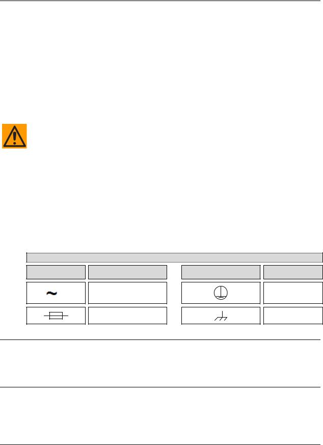
International Symbols
Symbol |
Definition |
Symbol |
Definition |
|
Alternating Current |
|
Protective Earth |
|
Fuse |
|
Chassis Ground |
Telecommunications Terminal Equipment Directive
In accordance with the Telecommunications Terminal Equipment Directive 91/263/EEC, this equipment should not be directly connected to the Public Telecommunications Network.
CE Mark
Comtech EF Data declares that the MDX420 modem meets the necessary requirements for the CE Mark.
iii

MDX420 SkyWire™ Satellite Network Gateway |
Revision 6 |
Preface |
MN-MDX420 |
RoHS Compliance
This unit satisfies (with exemptions) the requirements specified in the European Union Directive on the Restriction of Hazardous Substances, Directive 2002/95/EC (EU RoHS).
EMC (Electromagnetic Compatibility)
In accordance with European Directive 2004/108/EEC, the MDX420 has been shown, by independent testing, to comply with the following standards:
Emissions: EN 55022 Class B - Limits and methods of measurement of radio interference characteristics of Information Technology Equipment.
(Also tested to FCC Part 15 Class B.)
Immunity: EN 55024 – Information Technology Equipment: Immunity Characteristics, Limits, and Methods of Measurement.
Additionally, the MDX420 has been shown to comply with the following standards: EN 61000-3-2 – Harmonic Currents Emission;
EN 61000-3-3 – voltage Fluctuations and Flicker.
Connections to the transmit and receive IF ports should be made using a good quality coaxial cable. For example, RG58 or RG59 for BNC IF connectors and LMR200, LMR240 or equivalent for the L-band SMA IF ports.
All 'D' type connectors attached to the rear panel must have back-shells that provide continuous metallic shielding. Cable with a continuous outer shield (either foil or braid, or both) must be used, and the shield must be bonded to the back-shell.
The equipment must be operated with its cover on at all times. If it becomes necessary to remove the cover, the user should ensure that the cover is correctly re-fitted before normal operation commences.
iv

MDX420 SkyWire™ Satellite Network Gateway |
Revision 6 |
Preface |
MN-MDX420 |
Warranty Policy
Comtech EF Data products are warranted against defects in material and workmanship for a specific period from the date of shipment, and this period varies by product. In most cases, the warranty period is two years. During the warranty period, Comtech EF Data will, at its option, repair or replace products that prove to be defective. Repairs are warranted for the remainder of the original warranty or a 90 day extended warranty, whichever is longer. Contact Comtech EF Data for the warranty period specific to the product purchased.
For equipment under warranty, the owner is responsible for freight to Comtech EF Data and all related customs, taxes, tariffs, insurance, etc. Comtech EF Data is responsible for the freight charges only for return of the equipment from the factory to the owner. Comtech EF Data will return the equipment by the same method (i.e., Air, Express, Surface) as the equipment was sent to Comtech EF Data.
All equipment returned for warranty repair must have a valid RMA number issued prior to return and be marked clearly on the return packaging. Comtech EF Data strongly recommends all equipment be returned in its original packaging.
Comtech EF Data Corporation’s obligations under this warranty are limited to repair or replacement of failed parts, and the return shipment to the buyer of the repaired or replaced parts.
Limitations of Warranty
The warranty does not apply to any part of a product that has been installed, altered, repaired, or misused in any way that, in the opinion of Comtech EF Data Corporation, would affect the reliability or detracts from the performance of any part of the product, or is damaged as the result of use in a way or with equipment that had not been previously approved by Comtech EF Data Corporation.
The warranty does not apply to any product or parts thereof where the serial number or the serial number of any of its parts has been altered, defaced, or removed.
The warranty does not cover damage or loss incurred in transportation of the product.
The warranty does not cover replacement or repair necessitated by loss or damage from any cause beyond the control of Comtech EF Data Corporation, such as lightning or other natural and weather related events or wartime environments.
The warranty does not cover any labor involved in the removal and or reinstallation of warranted equipment or parts on site, or any labor required to diagnose the necessity for repair or replacement.
The warranty excludes any responsibility by Comtech EF Data Corporation for incidental or consequential damages arising from the use of the equipment or products, or for any inability to use them either separate from or in combination with any other equipment or products.
A fixed charge established for each product will be imposed for all equipment returned for warranty repair where Comtech EF Data Corporation cannot identify the cause of the reported failure.
Exclusive Remedies
Comtech EF Data Corporation’s warranty, as stated is in lieu of all other warranties, expressed, implied, or statutory, including those of merchantability and fitness for a particular purpose. The buyer shall pass on to any purchaser, lessee, or other user of Comtech EF Data Corporation’s products, the aforementioned warranty, and shall indemnify and hold harmless Comtech EF Data Corporation from any claims or liability of such purchaser, lessee, or user based upon allegations that the buyer, its agents, or employees have made additional warranties or representations as to product preference or use.
The remedies provided herein are the buyer’s sole and exclusive remedies. Comtech EF Data shall not be liable for any direct, indirect, special, incidental, or consequential damages, whether based on contract, tort, or any other legal theory.
v

MDX420 SkyWire™ Satellite Network Gateway |
Revision 6 |
Preface |
MN-MDX420 |
Product support
On the web
http://www.comtechefdata.com
Support business hours
Support Business Hours: Monday through Friday, 8:00 a.m. to 5:00 p.m. (MST)
After hours and weekends
Brand: |
Comtech EF Data |
Tel: +1.480.333.4357 |
Brand: |
Radyne |
Tel: +1.602.980.5220 |
Comtech EF Data and Radyne support contacts
Products |
Contact |
|
|
|
|
|
Satellite Modems |
Tel: +1.480.333.4357 |
|
Modem Accessories |
Fax: +1.480.333.2500 |
|
Amplifiers |
Email:techsupport@comtechefdata.com |
|
Converters |
|
|
Transceivers |
|
|
Terminals |
|
|
|
|
|
IP-Enabled Satellite Modems |
Tel: +1.480.333.2433 |
|
IP-Based Modem Accessories |
Fax: +1.480.333.2161 |
|
Encapsulators, Receivers, Filtering & Encryption |
Email:cdmipsupport@comtechefdata.com |
turboIP® Performance Enhancement Proxies (PEP) |
|
|
SkyWire™ MDX420 Satellite Network Gateway |
|
|
|
|
|
|
Vipersat Network Products |
Tel: +1.510.252.1462 - select option #2 |
|
IP-Enabled Satellite Modems used with VMS |
Fax: +1.510.252.1695 |
|
|
Email:supportcvni@comtechefdata.com |
|
|
|
vi
MDX420 SkyWire™ Satellite Network Gateway |
Introduction |
Chapter 1. INTRODUCTION
1.1SkyWire Product Overview
This manual provides detailed information for the Radyne SkyWire MDX420 Satellite Network Gateway. When describing the SkyWire gateway, it will be referred to as “the MDX420”, “the gateway”, “the network gateway”, or “the satellite gateway”. The next few sections will describe theory of operation, setup, accessing and monitoring the gateway.
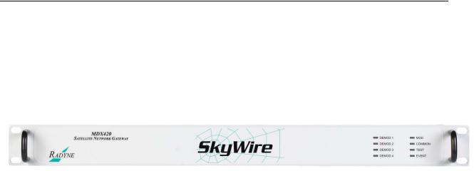
The Radyne SkyWire MDX420 Satellite Network Gateway (Figure 1-1 SkyWire Satellie Network Gateway) is a Closed Network Time Division Multiple Access (TDMA) Satellite Gateway specifically designed for satellite IP networks.
Figure 1-1 SkyWire Satellie Network Gateway
This satellite gateway combines unsurpassed performance with user-friendly remote access. Monitor and Control (M&C) functions are available through a secure SNMP V1, V2 or V3 interface. Operating parameters, such as symbol and data rates, FEC code rate, modulation type, IF/RF frequencies, and three levels of capacity management can be readily set and changed through the user interface by authorized earth station operations personnel.
The gateway operates over a data rate range of 328kbps to 21.6Mbps with a symbol rate range of 256ksps to 10Msps.
The gateway's data interface is an Ethernet Bridge 10/100/1000 Base-T interface.
The gateway supplies DC power to the LNB. The gateway has an optional feature to supply 24 or 48 volts to the BUC and an optional feature for a high stability 10MHz reference to the BUC and LNB. The capability to enable and disable the BUC/LNB voltages and 10MHz reference is available via the Ethernet SNMP control port. In addition, the gateway monitors both the current and the voltage at the output of the Tx and Rx Ports, thus providing the user verification of overall system status.
MN-MDX420 Revision 6 |
1–1 |
MDX420 SkyWire™ Satellite Network Gateway |
Introduction |
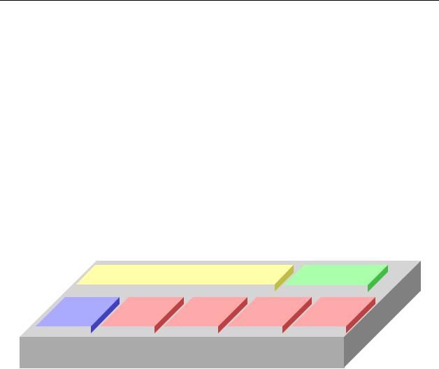
1.2MDX420 Simple Block Design
The MDX420 satellite gateway is based on a single signal processing printed circuit card designed with one to four optional plug in burst demodulator daughter cards. The minimum configuration consists of a single signal processing card and a single burst demodulator daughter card with the option to add three additional burst demodulators for a total of four burst demodulators. The single signal processing printed circuit board consists of an L-Band burst modulator, the Ethernet interface, and a digital baseband processor.
Within a SkyWire TDMA satellite network, a gateway has the ability to communicate with up to 32 full mesh remote sites in a single 1 RU chassis. All units at all locations are based on this single hardware platform.
Each gateway supports:
One burst Modulator (MOD)
Up to four burst Demods (DEMOD)
Network Control Module for distributed intelligence (NCM)
All gateway IP data traffic passes through a common 10/100/1000 bridge interface.
Optional BUC Power and 10Mhz Reference
|
|
|
10/100/1000 Switch |
|
|
|
|
NCM |
||||
|
|
|
|
|
|
|
||||||
|
|
|
|
|
|
|
|
|
|
|
|
|
MOD |
|
DEMOD 1 |
DEMOD 2 |
DEMOD 3 |
DEMOD 4 |
|||||||
|
|
|
|
|
|
|
|
|
|
|
|
|
|
|
|
|
|
|
|
|
|
|
|
|
|
MDX420
Figure 1-2 MDX420 Block Design
Each gateway can:
Transmit one carrier
Simultaneously receive four carriers that do not need to be of the same configuration.
Support a distributed leaderless TDMA network, meaning that there is no HUB and no single point of failure. The network administrator can log-in through any gateway in a share group and change the network parameters of any gateway in the share group
MN-MDX420 Revision 6 |
1–2 |
MDX420 SkyWire™ Satellite Network Gateway |
Introduction |
1.3Understanding TDMA
In a traditional Frequency Division Multiple Access (FDMA) system, a transponder resource is shared between a number of earth stations based on frequency allocations. In a FDMA system, an earth station will continuously transmit a single carrier on specific frequency broadcasting to a single receiver or multiple receivers at different earth stations.
In a TDMA system, a frequency allocation is shared between a number of earth stations based on time ‘slots’. Within a TDMA system, the transponder receives a sequential burst of transmissions from multiple earth stations broadcasting out to multiple receivers. In traditional “non-skywire” TDMA systems, the time plan for each earth station’s burst is determined by a central control system at a central location.
Time
Frequency
LNB |
|
LNB |
C |
|
C |
BU |
|
BU |
TX |
TX |
TX |
RX |
RX |
RX |
LNB  BUC
BUC
Figure 1-3 TDMA Access Example
Figure 1-3 shows an example of TDMA access of the satellite frequency allocation. In the example above, 3 remote sites are sharing a frequency allocation with each site transmitting sequentially. As stated above, in a TDMA platform, multiple sites “time share” their transmission on the same frequency carrier and data rates. The aggregate transmission will be received by a hub or participating remotes allowing each remote to determine which data they need to pass on to the local LAN. The aggregate transmission reflects multiple bursts from all 3 earth stations transmitting their IP data over satellite to the all sites in the network.
MN-MDX420 Revision 6 |
1–3 |
MDX420 SkyWire™ Satellite Network Gateway |
Introduction |
1.4SkyWire TDMA Network
The MDX420 gateway is designed for mesh communications. The gateway will transmit on a fixed carrier frequency and has the capability to receive up to 4 other carriers either on the same satellite or other satellites. A TDMA shared carrier can support up to 8 gateways all communicating on the same frequency allocation.
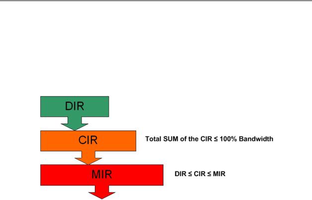
A SkyWire gateway determines the number of bursts it will transmit over satellite. The number of burst slots per frame is based on the local LAN needs and the needs of the other remotes in the share group. The gateway uses this information in conjunction with the operator specified Dedicated Information Rate (DIR), Committed Information Rate (CIR), and Maximum Information Rate (MIR) to determine how many burst slots it is allocated per frame.
Dedicated Information Rate - throughput in Kbits per second that cannot be used by anyone except the assigned gateway.
Committed Information Rate – throughput that is available to the user when ever requested, but is pooled when not in needed by the assigned gateway.
Maximum Information Rate – maximum throughput allowed by the gateway also referred to as the burstable throughput.
MN-MDX420 Revision 6 |
1–4 |
MDX420 SkyWire™ Satellite Network Gateway |
Introduction |
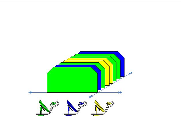
1.4.1 SkyWire Network Share Group
The MDX420 can support up to four burst demodulators. Each burst demodulator receives a single carrier or “share group” supporting up to 8 gateways. With two burst demodulators installed into an MDX420, a mesh network can now support up to 16 gateways with a single satellite hop connectivity. Since the MDX420 can have up to 4 burst demodulators installed, a gateway can receive 4 share groups supporting up to 32 gateways in a mesh network using only 1 burst modulator.
Figure 1-4 SkyWire RX System with Four Share Groups
MN-MDX420 Revision 6 |
1–5 |
MDX420 SkyWire™ Satellite Network Gateway |
Introduction |
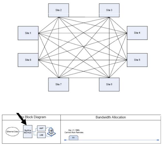
1.4.2 SkyWire Eight Site Mesh Network Example
The example below shows one share group consisting of 8 sites. Each site has a single MDX420 with 1 burst demodulator installed.
Figure 1-5 Eight site Full Mesh Network Diagram
One MDX420 per site
Figure 1-6 Eight Site Full Mesa Network Plan
MN-MDX420 Revision 6 |
1–6 |

MDX420 SkyWire™ Satellite Network Gateway |
Introduction |
1.4.3 SkyWire Sixteen Site Mesh Network Example
The example below (Figures 1-7 and 1-8) shows two share groups consisting of 16 gateways. Each gateway has a single MDX420 consisting of a single burst modulator and two burst demodulators. The addition of a second burst demodulator allows the network to support 16 gateways with a single hop.
Figure 1-7 Sixteen Site Full Mesh Network Diagram
One MDX420 per site
Figure 1-8 Sixteen Site Full Mesh Network Plan
MN-MDX420 Revision 6 |
1–7 |
MDX420 SkyWire™ Satellite Network Gateway |
Introduction |
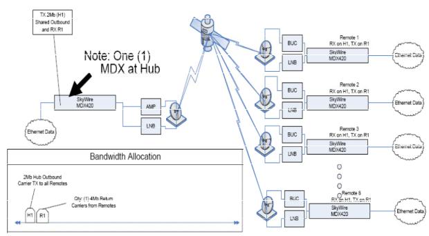
1.4.4 SkyWire Eight Site Hub / Spoke (Star) Network Example
The example below (Figure 1-9) shows an eight site Hub / Spoke network with a 2Mbps outbound shared carrier and a 4Mbit/s inbound shared carrier. Each gateway has a single MDX420 consisting of a single burst modulator and two burst demodulators. Remotes have a 256kbps CIR with burstable through-put up to 4Mbps.
Figure 1-9 Network Diagram of a HUB / SPOKE (Star) Network
MN-MDX420 Revision 6 |
1–8 |

MDX420 SkyWire™ Satellite Network Gateway |
Introduction |
1.5IP Ethernet Data Port
The IP data interface on the MDX420 is a dual port 10/100/1000 Ethernet bridge operating at the data link layer (layer 2). Refer to Appendix C for technical overview of the Gigabit Ethernet Bridge interface.
IP Data Ethernet interface supports:
Automatic learning & aging (stores forwarding database)
Auto Crossover
Auto Polarity
Auto Negotiation (Flow control)
Embedded Quality of Service
CRC Control
For the Ethernet Bridge interface to operate in a normal condition, there is nothing to configure, simply connect to one of the ports on the back panel.
The Ethernet Bridge interface allows all higher level protocols like IPv4, IPv6, DHCP, UDP, TCP, HTTP, and FTP to pass transparently.
1.5.1 Quality of Service (QoS)
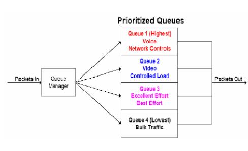
Most networks are comprised of various types of real time and non real time services. SkyWire offers basic layer 2/3 QoS control, allowing the user to prioritize data queues ensuring that higher priority traffic, like voice and network control, are not backed up behind lower priority traffic. SkyWire also supports queuing features that allow the user to prioritize queuing in different ways.
SkyWire Quality of Service (QoS) features includes:
Normal - Uses the following formats (IEEE 803.3ac Tag containing IEEE 802.1p priority information provided by an external device, Type of Service field (RFC 791) or Differentiated Services field (RFC 2474) contained in an IPv4 header and Traffic Class field (RFC 2460) contained in an IPv6 header.
Port Based - In this mode, physical port (J3) has the highest priority and physical port (J4) has the lowest priority. The Port Based priority overrides any other priority
SkyWire QoS QUEUE features include:
Fair Weighted - Selects the queue weighting of 8,4,2,1 allowing higher priority traffic to pass through more quickly and insures even the lowest priority traffic gets some bandwidth. Packets are processed in a weighted round robin manner with 8 having the highest priority.
Strict Priority - Ensures that the higher priority traffic will always be transmitted before any lower priority traffic. With this setting, higher priority traffic will be immediately transmitted until the buffer is empty starving all lower priority traffic until upper priority traffic is cleared.
MN-MDX420 Revision 6 |
1–9 |
MDX420 SkyWire™ Satellite Network Gateway |
Introduction |
Figure 1-10 QoS Priority Queuing
In certain circumstances it may be desirable to have the Ethernet Interface to operate in a FIFO like mode with no reordering of packets. This can be done by using a single port and setting the Ethernet QoS type to Port Base and the Ethernet QoS Queue to strict priority. This will allow packets to be transmitted in the exact order in which they are received.
1.5.2 CRC Control Satellite Packet Error Checking
Packet error checking is a standard part of any terrestrial Ethernet system and is performed using the CRC contained in the layer 2 Ethernet wrapper. The CRC is used as a checksum to detect alteration of data during transmission. When a CRC error is encountered, the packet is typically discarded by the router, switch, or hub in which the error was detected.
A similar methodology is utilized over the satellite link where bit errors result in a corrupted packet with a bad CRC. For most situations, the standard process of discarding these packets when they are encountered is the preferred methodology as the packet can simply be retransmitted.
However, there are some cases where the end device would rather receive the erred packet than no packet at all. Scenarios involving cryptography or where the end device has additional error correction capability are examples of two such situations. For these customers, the gateway provides the ability to turn off the satellite packet error checking and packets with bit errors will be output with a valid CRC so that they will properly pass to the connecting router or switch. Checking the CRC Control box in the Sattelite Demod Configuration GUI (normal operation) will look for a valid CRC and if not found will drop the Ethernet datagram. Unchecking the CRC control box will append a valid CRC to a potentially corrupt Ethernet datagram and pass the datagram to the next device in the chain. Note: CRC control only functions from the flow of satellite to the Ethernet LAN. Ethernet LAN to satellite flow will always drop bad CRC datagrams regardless of selection.
Regardless of the configuration of the CRC Control function, enabled or disabled, SkyWire maintains and reports satellite link statistics on total packets, erred packets, and packet error rate (PER).
MN-MDX420 Revision 6 |
1–10 |

MDX420 SkyWire™ Satellite Network Gateway |
SkyWire Hardware & Software Configurations |
Chapter 2. SkyWire Hardware &
Software Configurations
2.1SkyWire Features and Options
Hardware and software options are available at time of order. Some options are field upgradeable.
2.2Standard Configuration
The MDX420 comes standard with the following features:
AC Power
QPSK modulation with .710 and .793 FEC selection
Standard or Enhanced Eb/No operation
1Mbps maximum transmit data rate
1 Burst Modulator installed
1 Burst Demodulator installed
2.3Hardware Options
The items below identify specific hardware options and the availability of field upgrade (FLD) or only at time of order (TOR). Refer to Section 7.3.5, for information on how to view these features on the MDX420 GUI interface.
DC Input Prime Power (TOR)- Allows for an optional 48 Volt DC Input Power Source. This is a factory upgrade only.
BUC Power via the IF Output Connector (TOR)- Optional power supply can be added supporting 24 or 48 Volts to the BUC. This is a factory upgrade only
Additional Burst Demodulators (FLD)- MDX420 comes equipped with 1 burst demodulator and can be upgraded to add an additional 3 burst demodulator for a total of 4.
MN-MDX420 Revision 6 |
2–1 |
MDX420 SkyWire™ Satellite Network Gateway |
SkyWire Hardware & Software Configurations |
2.4Software Options
Software upgrades are a simple and quick way of adding new features to an installed gateway. Software upgrades can be easily installed via the GUI interface. Refer to Appendix A, for information on how upgrade features are enabled.
Maximum transmit data rate can be upgraded to 5Mbps, 10Mbps, or 20Mbps
8PSK modulation
2.5Hardware Field Upgrades
Hardware options are purchased parts that can be installed by the customer. Please contact the Comtech Corporation Sales Department for information on price, availability, and shipping costs.
Plug-In Burst Demodulator Cards: MDX420 can support up to 4 Burst Demodulators Cards.
CAUTION
Always make sure that power is removed from the unit before any optional modules are installed. Failure to do so may damage the equipment.
IMPORTANT
Make sure that only authorized service personnel handle and install hardware options.
MN-MDX420 Revision 6 |
2–2 |
MDX420 SkyWire™ Satellite Network Gateway |
Unpacking and Installation |
Chapter 3. Unpacking and Installation
This section provides unpacking and installation instructions.
3.1Installation Requirements
The gateway is designed to be installed within any standard 19-inch (48.26 cm) wide equipment cabinet or rack. It requires one rack unit (RU) of installation space (1.75 inches/4.45 cm) vertically and 13.0 inches (33.0 cm) of depth. Including cabling, a minimum of 16.0 inches (40.64 cm) of rack depth is required. The rear panel of the gateway has power entering from the left and IF Cabling entering from the right (as viewed from the rear of the gateway). Data and Control Cabling can enter from either side. Please refer to Section 4 for rear panel connector descriptions and pinouts. The gateway can be placed on a table or suitable surface if required.
WARNING
PROPER GROUNDING PROTECTION
During installation and setup, make sure that the gateway is properly grounded. The equipment shall be connected to the protective earth connection through the end user protective earth protection.
Also, make sure that the IF input and output coax cable shielding are correctly terminated to the Chassis ground.
WARNING
ELECTRICAL SHOCK HAZARD
There are no user-serviceable parts or configuration settings inside the
Chassis. A shock hazard exists internally at the power supply module.
DO NOT open the Chassis under any circumstances.
IMPORTANT
When installing the gateway in an equipment rack or any other method, adequate ventilation must be provided.
The ambient temperature inside the rack must be between 0 and 50 C, and held constant for best equipment operation.
The air available to the rack must be clean and relatively dry.
The gateways must not be placed immediately above a high-heat or EMF Generator to ensure the output signal integrity and proper receive operation.
DO NOT install the gateway in an unprotected location where there is direct contact with moisture, rain, snow, wind or sun.
MN-MDX420 Revision 6 |
3–1 |
MDX420 SkyWire™ Satellite Network Gateway |
Unpacking and Installation |
3.2Unpacking
The gateway was carefully packaged to avoid damage and should arrive complete with the following items for proper installation:
MDX420 Gateway Unit
Power Cord
Installation and Operation Manual
(GUI) Configuration Software CD
Documentation Package
The gateway is shipped fully assembled. It does not require removal of the covers for any purpose in installation.
3.3AC Power Requirements
The power supply is designed for universal AC application. If the available AC mains power at the installation site requires a different cord set from the one included in the package, then a suitable and approved cord set (for the country where the equipment is to be installed) will be required before proceeding with the installation.
Prime Power: 100 to 240VAC, 50 to 60 Hz Auto Sensing
Wattage: Base unit: less than 40 watts; Base unit with BUC Power: less than 200 Watts.
CAUTION
Before applying power to the gateway initially, disconnect the transmit output from the operating ground station equipment. If the current configuration settings are unknown when power is applied, incorrect settings could disrupt existing communications traffic.
3.4Installation Considerations
The only tools required for rack installation are four (4) customer-supplied rack installation screws and the appropriate screwdriver. Rack installation brackets are an integral part of the front bezel of the gateway and are not removable.
MN-MDX420 Revision 6 |
3–2 |
 Loading...