


 Loading...
KST-2000A/B
Ku-Band Satellite Transceiver
Installation and Operation Manual
IMPORTANT NOTE: The information contained in this document supercedes all previously published information regarding this product. Product specifications are subject to change
without prior notice.AB.IOM Revisio Part Number MN/KST2000AB.IOMPart Number MN/KST2000AB.IOM Revision 7 Part Number MN/KST2000AB.IOM Revision 9

KST-2000A/B
Ku-Band Satellite Transceiver
Installation and Operation Manual
Comtech EF Data is an ISO 9001
Registered Company.
Part Number
Revision 9
June 25, 2007
Copyright © Comtech EF Data, 2007. All rights reserved. Printed in the USA.
Comtech EF Data, 2114 West 7th Street, Tempe, Arizona 85281 USA, 480.333.2200, FAX: 480. 333.2161

Ku-Band Satellite Transceiver |
Revision 9 |
Preface |
MN/KST2000AB.IOM |
Customer Service
Contact the Comtech EF Data Customer Support Department for:
•Product support or training
•Reporting comments or suggestions concerning manuals
•Information on upgrading or returning a product
A Customer Support representative may be reached at:
Comtech EF Data
Attention: Customer Support Department 2114 West 7th Street
Tempe, Arizona 85281 USA
480.333.2200 (Main Comtech EF Data Number)
480.333.4357 (Customer Support Desk)
480.333.2161 FAX
To return a Comtech EF Data product (in-warranty and out-of-warranty) for repair or replacement:
•Contact the Comtech EF Data Customer Support Department. Be prepared to supply the Customer Support representative with the model number, serial number, and a description of the problem.
•Request a Return Material Authorization (RMA) number from the Comtech EF Data Customer Support representative.
•Pack the product in its original shipping carton/packaging to ensure that the product is not damaged during shipping.
•Ship the product back to Comtech EF Data. (Shipping charges should be prepaid.)
For Online Customer Support:
An RMA number request can be requested electronically by contacting the Customer Support Department through the online support page at www.comtechefdata.com/support.asp.
Click on the “RMA Request Form” hyperlink, then fill out the form completely before sending.
Click on “Return Material Authorization” for detailed instructions on our return procedures.
Send e-mail to the Customer Support Department at service@comtechefdata.com.
For information regarding this product’s warranty policy, refer to page xi.
ii

Ku-Band Satellite Transceiver |
Revision 9 |
Preface |
MN/KST2000AB.IOM |
Table of Contents
Customer Service ...................................................................................................................................... |
ii |
|||
About this Manual ................................................................................................................................... |
ix |
|||
Warnings and Cautions........................................................................................................................... |
ix |
|||
Installation Guidelines Regarding Power Line Quality ........................................................................ |
x |
|||
Warranty Policy....................................................................................................................................... |
xi |
|||
CHAPTER 1. |
INTRODUCTION ........................................................................................... |
1–1 |
||
1.1 |
Description................................................................................................................................. |
1–2 |
||
1.1.1 |
|
Receive Reject Filter.......................................................................................................... |
1–2 |
|
1.1.2 |
|
Recommended Maintenance .............................................................................................. |
1–3 |
|
1.1.3 |
|
Areas of Operation:............................................................................................................ |
1–3 |
|
1.1.4 |
|
Features ............................................................................................................................... |
1–4 |
|
1.1.5 |
|
Single-Thread KST-2000A System .................................................................................... |
1–6 |
|
1.1.6 |
|
Single-Thread KST-2000B System .................................................................................... |
1–8 |
|
1.1.7 |
|
Redundant System .............................................................................................................. |
1–9 |
|
1.2 |
Specifications ........................................................................................................................... |
1–10 |
||
CHAPTER 2. |
INSTALLATION............................................................................................. |
2–1 |
||
2.1. |
Single-Thread System Components......................................................................................... |
2–1 |
||
2.2. |
Redundant System Components.............................................................................................. |
2–2 |
||
2.3. |
Description of Options.............................................................................................................. |
2–3 |
||
2.4. |
Electrical Connections .............................................................................................................. |
2–4 |
||
2.4.1. |
Converter Unit .................................................................................................................... |
2–4 |
||
2.4.2. |
Data SSPAs....................................................................................................................... |
2–13 |
||
2.4.3. |
LNA Connections ............................................................................................................. |
2–20 |
||
2.4.4. |
LNB Connections.............................................................................................................. |
2–20 |
||
CHAPTER 3. |
OPERATION.................................................................................................. |
3–1 |
||
3.1 |
Initial Setup (Single-Thread System) ...................................................................................... |
3–1 |
||
3.1.1 |
|
Uplink Setup ....................................................................................................................... |
3–3 |
|
3.1.2 |
|
Downlink Setup .................................................................................................................. |
3–4 |
|
3.2 |
Initial Setup Redundant System .............................................................................................. |
3–5 |
||
iii

Ku-Band Satellite Transceiver |
Revision 9 |
||
Preface |
|
MN/KST2000AB.IOM |
|
3.3 |
Redundant Junction Unit Description .................................................................................... |
3–8 |
|
3.3.1 |
|
3.3.1 RJU-2000 Description................................................................................................ |
3–9 |
3.4 |
Connector Descriptions .......................................................................................................... |
3–10 |
|
3.4.1 |
|
TX Switch Connector (J1) ................................................................................................ |
3–10 |
3.4.2 |
|
RX Switch Connector (J2) ................................................................................................ |
3–10 |
3.4.3 |
|
1:1 Interface Connector (J3) ............................................................................................. |
3–11 |
3.4.4 |
|
RFTA Remote Interface Connector (J4) ........................................................................... |
3–12 |
3.4.5 |
|
RFTB Remote Interface Connector (J5) ........................................................................... |
3–13 |
3.4.6 |
|
Interface M&C Connector (J6) ......................................................................................... |
3–14 |
3.4.7 |
|
Other Connectors .............................................................................................................. |
3–15 |
3.5 |
Indicators Description ............................................................................................................ |
3–15 |
|
3.6 |
1:1 Redundant KST-2000A/B System Operation................................................................. |
3–16 |
|
3.7 |
Reference Oscillator................................................................................................................ |
3–22 |
|
3.8 |
Monitor and Control (M&C)................................................................................................. |
3–23 |
|
3.8.1 |
|
Up Converter Description ................................................................................................. |
3–25 |
3.9 |
Kuto L-Band Down Converter Description (KST-2000A)................................................ |
3–26 |
|
3.10 |
L-Band to IF Down Converter Description (KST-2000A/B) .............................................. |
3–27 |
|
3.11 |
Automatic Gain Control (AGC) ............................................................................................ |
3–28 |
|
3.11.1 |
Operation........................................................................................................................... |
3–29 |
|
3.11.2 Fault and Error Response.................................................................................................. |
3–30 |
||
3.11.3 |
Manual Gain Operation..................................................................................................... |
3–31 |
|
CHAPTER 4. FAULT INDICATION AND ISOLATION........................................................ |
4–1 |
||
4.1 |
Fault Indication......................................................................................................................... |
4–1 |
|
4.2 |
Fault Isolation............................................................................................................................ |
4–2 |
|
4.3 |
Stored Faults.............................................................................................................................. |
4–2 |
|
CHAPTER 5. KEYPAD / DISPLAY ........................................................................................... |
1 |
||
5.1 |
Keypad/Display Overview............................................................................................................ |
1 |
|
5.2 |
Front Panel Keypad/Display....................................................................................................... |
2 |
|
5.2.1 |
|
Front Panel Controls .............................................................................................................. |
3 |
5.3 |
The Menu Structure..................................................................................................................... |
5 |
|
5.3.1 |
|
Configuration ........................................................................................................................... |
6 |
iv

Ku-Band Satellite Transceiver |
Revision 9 |
||
Preface |
|
MN/KST2000AB.IOM |
|
5.3.2 |
Monitor ..................................................................................................................................... |
9 |
|
5.3.3 |
Faults....................................................................................................................................... |
10 |
|
5.3.4 |
Utility....................................................................................................................................... |
13 |
|
5.3.5 |
System ..................................................................................................................................... |
14 |
|
5.3.6 |
Redundancy.......................................................................................................................... |
16 |
|
APPENDIX A. EQUIPMENT OUTLINE DRAWINGS ......................................................... |
A–1 |
||
A.1 |
2 and 4 Watt SSPA Equipment Outline................................................................................. |
A–2 |
|
A.2 |
8 Watt SSPA Equipment Outline ........................................................................................... |
A–3 |
|
A.3 |
16 Watt SSPA Equipment Outline ......................................................................................... |
A–4 |
|
A.4 |
25/32/40 Watt SSPA Equipment Outline ............................................................................... |
A–5 |
|
A.5 |
Ku-Band LNA Equipment Outline......................................................................................... |
A–6 |
|
A.6 |
KST-2000A/B Converter Equipment Outline ....................................................................... |
A–7 |
|
A.7 |
Ku-Band LNB Equipment Outline......................................................................................... |
A–8 |
|
APPENDIX B. TERMINAL MODE COMMANDS ................................................................ |
B–1 |
||
B.1 |
General....................................................................................................................................... |
B–1 |
|
B.2 |
Message Structure..................................................................................................................... |
B–2 |
|
B.2.1 |
Start Character..................................................................................................................... |
B–2 |
|
B.2.2 |
Device Address ................................................................................................................... |
B–2 |
|
B.2.3 |
Command/Response........................................................................................................... |
B–3 |
|
B.2.3 |
End Character...................................................................................................................... |
B–4 |
|
B.3 |
System Configuration Commands........................................................................................... |
B–4 |
|
B.3.1 |
Configuration Commands/Responses ................................................................................. |
B–5 |
|
B.3.2 |
System Configuration Commands ...................................................................................... |
B–6 |
|
B.3.3 |
Reset Commands................................................................................................................. |
B–8 |
|
B.3.4 |
Status Commands/Responses.............................................................................................. |
B–8 |
|
B.3.5 |
Stored Faults........................................................................................................................ |
B–11 |
|
B.3.6 |
Miscellaneous ................................................................................................................... |
B–14 |
|
B.4 |
Backup Operations/Self-Contained Redundancy ................................................................ |
B–15 |
|
B.4.1 |
External Fault Mode ......................................................................................................... |
B–16 |
|
B.5 |
Keypad/Display Related Commands .................................................................................... |
B–16 |
|
APPENDIX C. SINGLE-THREAD EQUIPMENT MOUNTING............................................. |
C–1 |
||
v

Ku-Band Satellite Transceiver |
Revision 9 |
||
Preface |
|
MN/KST2000AB.IOM |
|
C.1 |
Tools Required ......................................................................................................................... |
C–2 |
|
C.2 |
Converter Unit Installation..................................................................................................... |
C–3 |
|
C.2.1 |
Spar Arm Mount ................................................................................................................. |
C–3 |
|
C.2.2 |
Pole Mount.......................................................................................................................... |
C–6 |
|
C.3 |
SSPA Installation ................................................................................................................... |
C–10 |
|
C.3.1 |
Feed Mount Offset Antenna.............................................................................................. |
C–10 |
|
C.4 |
LNA Installation..................................................................................................................... |
C–13 |
|
C.4.1 |
Feed Mount Offset Antenna.............................................................................................. |
C–13 |
|
C.5 |
Cable Installation ................................................................................................................... |
C–14 |
|
APPENDIX D. REDUNDANT EQUIPMENT MOUNTING.................................................... |
D–1 |
||
D.1 |
Tools Required ......................................................................................................................... |
D–2 |
|
D.2 |
1:1 Converters Installation...................................................................................................... |
D–3 |
|
D.2.1 |
Spar Arm Mount ................................................................................................................ |
D–3 |
|
D.2.2 |
Pole Mount......................................................................................................................... |
D–6 |
|
D.3 |
1:1 SSPA Installation............................................................................................................. |
D–10 |
|
D.3.1 |
Feed Mount Offset Antenna............................................................................................. |
D–10 |
|
D.4 |
1:1 LNA Installation .............................................................................................................. |
D–11 |
|
D.4.1 |
Feed Mount Offset Antenna............................................................................................. |
D–11 |
|
D.5 |
Cable Installation ................................................................................................................... |
D–11 |
|
APPENDIX E. FSK REMOTE CONTROL COMMANDS..................................................... |
E–1 |
||
E.1 |
Introduction............................................................................................................................... |
E–1 |
|
E.2 |
Basic Protocol ............................................................................................................................ |
E–2 |
|
E.2.1 |
Packet Structure .................................................................................................................. |
E–3 |
|
E.2.2 |
Start Of Packet .................................................................................................................... |
E–3 |
|
E.2.3 |
Address ............................................................................................................................... |
E–3 |
|
E.2.4 |
Instruction Code.................................................................................................................. |
E–3 |
|
E.2.5 |
Instruction Code Qualifier .................................................................................................. |
E–4 |
|
E.2.6 |
Message Arguments............................................................................................................ |
E–6 |
|
E.2.7 |
End Of Packet ..................................................................................................................... |
E–6 |
|
E.3 |
Commands and Query.............................................................................................................. |
E–6 |
|
GLOSSARY ..................................................................................................................... |
g–1 |
||
vi

Ku-Band Satellite Transceiver |
Revision 9 |
Preface |
MN/KST2000AB.IOM |
INDEX ...................................................................................................................... |
i–1 |
Figures
FIGURE 1-1. KST-2000A/B CONVERTER UNIT AND 8 WATT SSPA ........................................... |
1–1 |
FIGURE 1-2. RECEIVE REJECT FILTER .......................................................................................... |
1–2 |
FIGURE 1-3. SINGLE THREAD KST-2000A SYSTEM ..................................................................... |
1–6 |
FIGURE 1-4. SINGLE THREAD KST-2000B BLOCK DIAGRAM ................................................... |
1–8 |
FIGURE 1-5. REDUNDANT KST-2000A SYSTEM BLOCK DIAGRAM ......................................... |
1–9 |
FIGURE 2-1. I/O VIEW OF KST-2000A/B CONVERTER UNIT ...................................................... |
2–4 |
FIGURE 2-2. PRIME POWER INPUT (J1).......................................................................................... |
2–5 |
FIGURE 2-3. SERIAL (EIA-232) ADAPTER CABLE WIRING DIAGRAM .................................... |
2–7 |
FIGURE 2-4. 16WATT SSPA............................................................................................................. |
2–14 |
FIGURE 2-5. I/O CONNECTORS FOR THE 16 WATT SSPA ........................................................ |
2–15 |
FIGURE 2-6. OUTPUT CONNECTION FOR THE 16 WATT SSPA (WAVEGUIDE)................... |
2–16 |
FIGURE 2-7. 25/32/40 WATT SSPA ................................................................................................. |
2–17 |
FIGURE 2-8. I/O CONNECTORS FOR THE 25/32/40 WATT SSPA .............................................. |
2–18 |
FIGURE 2-9. OUTPUT CONNECTION FOR THE 25/32/40 WATT SSPA (WAVEGUIDE)......... |
2–19 |
FIGURE 3-1. SINGLE-THREAD SYSTEM ........................................................................................ |
3–2 |
FIGURE 3-2. 1:1 REDUNDANT SYSTEM BLOCK DIAGRAM....................................................... |
3–7 |
FIGURE 3-3. RJU-2000 FRONT PANEL ............................................................................................ |
3–8 |
FIGURE 3-4. RJU-2000 BLOCK DIAGRAM...................................................................................... |
3–9 |
FIGURE 3-5. REDUNDANT KST-2000A/B SYSTEM SHOWING UNITS A AND B DESIGNATION |
|
...................................................................................................................................................... |
3–17 |
FIGURE 3-6. REDUNDANT HPA ASSEMBLY............................................................................... |
3–18 |
FIGURE 3-7. REDUNDANT LNA/B ASSEMBLY........................................................................... |
3–19 |
FIGURE 3-8. REFERENCE OSCILLATOR ...................................................................................... |
3–22 |
FIGURE 3-9. MONITOR AND CONTROL (M&C) BLOCK DIAGRAM ....................................... |
3–23 |
FIGURE 3-10. IF TO S-BAND CONVERTER MODULE BLOCK DIAGRAM.............................. |
3–25 |
FIGURE 3-11. S TO KU-BAND UP CONVERTER MODULE........................................................ |
3–26 |
FIGURE 3-12. KU TO L-BAND DOWN CONVERTER MODULE BLOCK DIAGRAM.............. |
3–26 |
FIGURE 3-13. L-BAND TO IF DOWN CONVERTER BLOCK DIAGRAM .................................. |
3–27 |
FIGURE 3-14. AGC OPERATING REGION..................................................................................... |
3–31 |
FIGURE 5-1. KST-2000A/B TERMINAL KEYPAD........................................................................... |
5–2 |
FIGURE 5-2. KST-2000A/B SIGN ON MESSAGE............................................................................. |
5–3 |
FIGURE 5-3. PRINCIPLE MENU TREES........................................................................................... |
5–4 |
FIGURE 5-4. SELECT MENU ............................................................................................................. |
5–5 |
FIGURE 5- 5. CONFIGURATION MENU ........................................................................................... |
5–6 |
FIGURE 5-6. MONITOR MENU ......................................................................................................... |
5–9 |
FIGURE 5-7. FAULTS MENU FIGURE 5-8. FAULTS SUB-LEVEL ........................................ |
5–10 |
FIGURE 5-9. UTILITY MENU ........................................................................................................... |
5–13 |
FIGURE 5-10. SYSTEM MENU ........................................................................................................ |
5–14 |
FIGURE 5-11. REDUNDANCY MENU ............................................................................................ |
5–16 |
FIGURE A-1. 2 AND 4 WATT SSPA EQUIPMENT OUTLINE ....................................................... |
A–2 |
FIGURE A-2. 8 WATT SSPA EQUIPMENT OUTLINE.................................................................... |
A–3 |
FIGURE A-3. 16 WATT SSPA EQUIPMENT OUTLINE.................................................................. |
A–4 |
FIGURE A-4. 25/32/40 WATT SSPA EQUIPMENT OUTLINE ....................................................... |
A–5 |
vii

Ku-Band Satellite Transceiver |
|
Revision 9 |
Preface |
MN/KST2000AB.IOM |
|
FIGURE A-5. KU-BAND LNA EQUIPMENT OUTLINE ................................................................. |
|
A–6 |
FIGURE A-6. KST-2000A/B CONVERTER EQUIPMENT OUTLINE ............................................ |
|
A–7 |
FIGURE A-7. KU-BAND LNB EQUIPMENT OUTLINE ................................................................. |
|
A–8 |
FIGURE C-1. KST-2000A SINGLE THREAD SYSTEM INSTALLED ON SPAR ARM................. |
C–2 |
|
FIGURE C-2. TYPICAL CONVERTER UNIT INSTALLATION ON SPAR .................................... |
|
C–5 |
FIGURE C-3. KST-2000A CONVERTER WITH MOUNTING BRACKETS.................................... |
|
C–7 |
FIGURE C-4. REAR VIEW OF CONVERTER INSTALLED ON ROUND POLE .......................... |
|
C–8 |
FIGURE C-5. FRONT VIEW OF CONVERTER INSTALLED ON ROUND POLE........................ |
|
C–9 |
FIGURE C-6. INSTALLING THE SSPA ........................................................................................... |
|
C–11 |
FIGURE C-7. SSPA INSTALLED...................................................................................................... |
|
C–12 |
FIGURE D-1. 1:1 SYSTEM INSTALLED ON SPAR ARM .............................................................. |
|
D–2 |
FIGURE D-2. CONVERTERS AND SSPAS ON SPAR ARM........................................................... |
|
D–5 |
FIGURE D-3. KST-2000A 1:1 CONVERTERS WITH MOUNTING BRACKETS .......................... |
|
D–7 |
FIGURE D-4. REAR VIEW OF CONVERTERS INSTALLED ON POLE ....................................... |
|
D–9 |
FIGURE D-5. FRONT VIEW OF CONVERTERS INSTALLED ON POLE..................................... |
|
D–9 |
Tables |
|
|
TABLE 1-1. FEATURES ...................................................................................................................... |
|
1–5 |
TABLE 1-2. CONVERTER UNIT SPECIFICATIONS ...................................................................... |
|
1–10 |
TABLE 1-3. SYSTEM TRANSMIT CHARACTERISTICS (WITH SSPAS OF ≤ 40W) .................. |
1–11 |
|
TABLE 1-4. LNA CHARACTERISTICS............................................................................................ |
|
1–12 |
TABLE 1-5. LNB CHARACTERISTICS ............................................................................................ |
|
1–12 |
TABLE 1–6. SSPA CHARACTERISTICS.......................................................................................... |
|
1–13 |
TABLE 2-1. DESCRIPTION OF OPTIONS......................................................................................... |
|
2–3 |
TABLE 2-2. CONVERTER UNIT EXTERNAL CONNECTIONS...................................................... |
|
2–5 |
TABLE 2-3. REMOTE M&C CONNECTOR (J2) PIN ASSIGNMENTS........................................... |
|
2–6 |
TABLE 2-4. HPA CONNECTOR (J8) PIN ASSIGNMENTS (CEFD SSPA) ................................... |
|
2–10 |
TABLE 2-5. HPA CONNECTOR (J8) PIN ASSIGNMENTS (NON-KST SPECIFIC SSPA).......... |
2–10 |
|
TABLE 2-6. HPA CONNECTOR (J8) PIN ASSIGNMENTS (TWTA CONNECTION)................... |
2–11 |
|
TABLE 2-7. 1:1 CONNECTOR (J10) PIN ASSIGNMENTS ............................................................ |
|
2–12 |
TABLE 2-8. FAN (J4) PIN ASSIGNMENTS..................................................................................... |
|
2–13 |
TABLE 3-1. CONNECTOR J1 PINOUT DESCRIPTION................................................................. |
|
3–10 |
TABLE 3-2. CONNECTOR J2 PINOUT DESCRIPTION................................................................. |
|
3–10 |
TABLE 3-3. 1:1 INTERFACE CONNECTOR J3 PINOUT DESCRIPTION.................................... |
|
3–11 |
TABLE 3-4. RFTA REMOTE INTERFACE CONNECTOR J4 PINOUT DESCRIPTION.............. |
3–12 |
|
TABLE 3-5. RFTB REMOTE INTERFACE CONNECTOR J5 PINOUT DESCRIPTION.............. |
3–13 |
|
TABLE 3-6. INTERFACE M&C CONNECTOR J6 PINOUT DESCRIPTION................................ |
|
3–14 |
TABLE 3-7. AGC FAULT AND ERROR RESPONSE ..................................................................... |
|
3–30 |
TABLE 4-1. KST-2000A/B FAULT TREE .......................................................................................... |
|
4–3 |
viii
Ku-Band Satellite Transceiver |
Revision 9 |
Preface |
MN/KST2000AB.IOM |
Preface
About this Manual
This manual provides installation and operation information for the Comtech EF Data Ku-Band Satellite Transceiver. This is a technical document intended for earth station engineers, technicians, and operators responsible for the operation and maintenance of the KST-2000A/B.
Trademarks
Product names mentioned in this manual may be trademarks or registered trademarks of their respective companies and are hereby acknowledged.
Warnings and Cautions
WARNING
CAUTION
IMPORTANT
WARNING indicates a potentially hazardous situation that, if not avoided, could result in death or serious injury.
CAUTION indicates a hazardous situation that, if not avoided, may result in minor or moderate injury. CAUTION may also be used to indicate other unsafe practices or risks of property damage.
Indicates information critical for proper equipment function.
Reporting Comments or Suggestions Concerning this Manual
ix

Ku-Band Satellite Transceiver |
Revision 9 |
Preface |
MN/KST2000AB.IOM |
Comments and suggestions regarding the content and design of this manual will be appreciated. To submit comments, please contact the Comtech EF Data Technical Publications Department.
Related Documents
•Comtech EF Data KP-10 External Keypad Installation and Operation Manual
•Comtech EF Data Windows based Monitor and Control software for Comtech EFData Satellite Terminals Installation and Operation Manual, part number MN/M&CWIN.IOM.
Installation Guidelines Regarding Power Line Quality
As a company with many years of experience selling and servicing equipment installed around the world, Comtech EF Data has become familiar with the varying quality of the AC power grid around the world. The following offers some installation guidelines that should help ensure a reliable installation.
•Surge suppression: High voltage surges can cause failure of the power supply. These surges are typically caused by circuit switching on the main AC power grid, erratic generator operation, and also by lightning strikes. While the transceiver does have built in surge suppression, if the unit will be installed in a location with questionable power grid quality, Comtech EF Data recommends installation of additional power conditioning/surge suppression at the power junction box.
•Grounding: The transceiver provides a grounding terminal. This is provided to allow the user to ground the transceiver to the antenna’s grounding network. All components installed at the antenna shall be grounded to a common grounding point at the antenna.
•Electrical welding: If welding needs to take place at the antenna, disconnect all cables from the transceiver except for the ground wire. Cap all RF connections with terminations. This will prevent damage to the input/output circuitry of the transceiver.
•Lightning: Lightning strikes on or around the antenna will generate extremely high voltages on all cables connected to the transceiver. Depending on the severity of the strike, the transceivers internal surge protection combined with the recommended external suppression may protect the transceivers power supply. However, if the installation will be in an area with a high probability of lightning strikes, Comtech EF Data recommends the installation of surge suppression on the RF and IF cables. One source of these suppressors is PolyPhaser (www.polyphaser.com)
For further information, please contact Comtech EF Data.
x

Ku-Band Satellite Transceiver |
Revision 9 |
Preface |
MN/KST2000AB.IOM |
Warranty Policy
Comtech EF Data products are warranted against defects in material and workmanship for a period of two years from the date of shipment. During the warranty period, Comtech EF Data will, at its option, repair or replace products that prove to be defective.
For equipment under warranty, the owner is responsible for freight to Comtech EF Data and all related customs, taxes, tariffs, insurance, etc. Comtech EF Data is responsible for the freight charges only for return of the equipment from the factory to the owner.
Comtech EF Data will return the equipment by the same method (i.e., Air, Express, Surface) as the equipment was sent to Comtech EF Data.
All equipment returned for warranty repair must have a valid RMA number issued prior to return and be marked clearly on the return packaging. Comtech EF Data strongly recommends all equipment be returned in its original packaging.
Comtech EF Data Corporation’s obligations under this warranty are limited to repair or replacement of failed parts, and the return shipment to the buyer of the repaired or replaced parts.
Limitations of Warranty
The warranty does not apply to any part of a product that has been installed, altered, repaired, or misused in any way that, in the opinion of Comtech EF Data Corporation, would affect the reliability or detracts from the performance of any part of the product, or is damaged as the result of use in a way or with equipment that had not been previously approved by Comtech EF Data Corporation.
The warranty does not apply to any product or parts thereof where the serial number or the serial number of any of its parts has been altered, defaced, or removed.
The warranty does not cover damage or loss incurred in transportation of the product.
The warranty does not cover replacement or repair necessitated by loss or damage from any cause beyond the control of Comtech EF Data Corporation, such as lightning or other natural and weather related events or wartime environments.
The warranty does not cover any labor involved in the removal and or reinstallation of warranted equipment or parts on site, or any labor required to diagnose the necessity for repair or replacement.
The warranty excludes any responsibility by Comtech EF Data Corporation for incidental or consequential damages arising from the use of the equipment or products, or for any inability to use them either separate from or in combination with any other equipment or products.
A fixed charge established for each product will be imposed for all equipment returned for warranty repair where Comtech EF Data Corporation cannot identify the cause of the reported failure.
xi

Ku-Band Satellite Transceiver |
Revision 9 |
Preface |
MN/KST2000AB.IOM |
Exclusive Remedies
Comtech EF Data Corporation’s warranty, as stated is in lieu of all other warranties, expressed, implied, or statutory, including those of merchantability and fitness for a particular purpose. The buyer shall pass on to any purchaser, lessee, or other user of Comtech EF Data Corporation’s products, the aforementioned warranty, and shall indemnify and hold harmless Comtech EF Data Corporation from any claims or liability of such purchaser, lessee, or user based upon allegations that the buyer, its agents, or employees have made additional warranties or representations as to product preference or use.
The remedies provided herein are the buyer’s sole and exclusive remedies. Comtech EF Data shall not be liable for any direct, indirect, special, incidental, or consequential damages, whether based on contract, tort, or any other legal theory.
xii
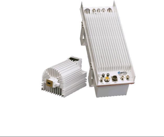
Chapter 1. INTRODUCTION
This chapter provides a description and the specifications for the KST-2000A/B satellite terminal system. The converter unit and 8 Watt SSPA are shown in Figure 1-1.
Figure 1-1. KST-2000A/B Converter Unit and 8 Watt SSPA
Various configurations of the KST-2000A/B Ku-Band satellite terminal system are available with both optional and standard equipment.
1–1
KuBand Satellite Transceiver |
Revision 9 |
Introduction |
MN/KST2000AB.IOM |
1.1Description
The KST-2000A/B Ku-Band satellite terminal is a high-performance, full-featured transceiver designed for outdoor operation. The converter unit controls external High Power Amplifiers (HPAs). Automatic Gain Control (AGC) from the converter input to the HPA output assures power output stability over varying conditions for up to 40W Comtech EF Data Solid-State Power Amplifier (SSPAs).
Note: For TX only application, downlink functions and hardware are not supplied or available.
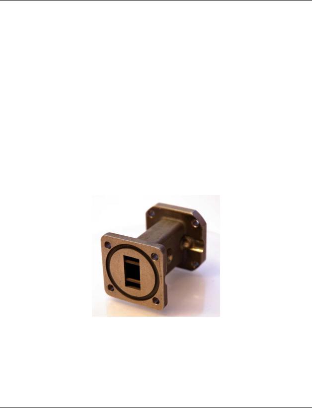
1.1.1Receive Reject Filter
The KST-2000A/B is capable of operating over an uplink frequency of 13.75 to 14.5 GHz. Due to the proximity of the lower end of this band to the upper end of the Ku receive band, it is possible for the upconverter to radiate noise power in the upper range of the receive band.
If the transceiver Rx frequency is above 11.9 GHz, Comtech EF Data recommends installing the supplied Receive Reject Filter (Figure 1-2) on the output of the SSPA for single-thread systems and the output of the switch on redundant systems.
Figure 1-2. Receive Reject Filter
1–2

KuBand Satellite Transceiver |
Revision 9 |
Introduction |
MN/KST2000AB.IOM |
1.1.2Recommended Maintenance
The fans utilized by the KST SSPAs are designed for long life even in a harsh environment. They are still mechanical devices subject to wear and may need replacement after several years. Industry environments, fan shroud removal facilitates clearing the heat sink of accumulated dust.
Once a year (or sooner depending on environmental conditions), the SSPA heat sink should be cleaned.
To perform this maintenance:
1.Disconnect power from the SSPA
2.Remove the fan shroud assembly
3.Using compressed air, blow through the SSPA heat sink to remove any foreign object accumulation that may be obstructing airflow.
4.Reinstall the supply and fan assembly.
No routine maintenance is required for the KST base unit.
1.1.3Areas of Operation:
The areas of operation are as follows:
Converter |
Convection cooled up/down converter with an internal |
|
power supply and microprocessor-based Monitor and |
|
Control (M&C). The converter contains a wide band block |
|
Kuto L-Band down converter in the KST-2000A, or this |
|
function may be performed in an external Low Noise |
|
Block converter (LNB) in the KST-2000B. |
HPA |
Offered with various power output capabilities. |
KST-2000A Only – Low Noise |
LNAs with and without a Transmit Reject Filter (TRF) and |
Amplifier (LNA) |
various noise temperatures or noise figures are available. |
KST–2000B Only – Low Noise |
LNBs with various frequency coverage are available. |
Block (LNB) Assembly |
|
FSK Remote Commands (Single- |
Modifications have been made to the KST-2000A |
Thread Configuration only) |
firmware and hardware to permit monitor and control |
|
from the front panel of select Comtech EF Data Satellite |
|
Modems. Currently the CDM-550T and CDM-600 |
|
modems can monitor and control the KST-2000A. This |
|
control is transmitted via an FSK signal superimposed on |
|
the RX connection. |
|
|
1–3

KuBand Satellite Transceiver |
Revision 9 |
Introduction |
MN/KST2000AB.IOM |
1.1.4Features
1.1.4.1Full Ku-Band Transmit and Receive Coverage
KST-2000A Only
13.75 to 14.5 GHz |
Transmit range in 1 |
MHz |
14.00 to 14.5 GHz |
Transmit range in 1 |
MHz (Optional) |
10.95 to 12.75 GHz |
Receive range in 1 MHz steps |
|
KST-2000B Only
13.75 to 14.5 GHz |
Transmit range in 1 |
MHz steps for HPAs of ≤ 40W |
14.00 to 14.5 GHz |
Transmit range in 1 |
MHz steps for HPAs of > 40W (Optional) |
10.95 to 11.70 GHz |
LNB-Select: Receive range in 1 MHz steps |
|
11.70 to 12.20 GHz |
|
|
12.25 to 12.75 GHz |
|
|
1–4

KuBand Satellite Transceiver |
Revision 9 |
Introduction |
MN/KST2000AB.IOM |
1.1.4.2 Other Features
|
|
|
Table 1-1. Features |
|
|
|
|
Feature |
|
|
Description |
Automatic Gain |
|
The KST-2000A/B incorporates a closed loop control system that |
|
Control |
|
maintains the system’s conversion gain (as measured from the IF input to |
|
|
|
the Ku-Band SSPA output) at the user’s preset value despite the effects |
|
|
|
of temperature, aging, and cable loss. This feature is provided for use |
|
|
|
with Comtech EF Data SSPAs up to and including 40W. |
|
Optional IF |
|
Optional on ordering. |
|
Input/Output of 70 or |
|
|
|
140 MHz |
|
|
|
Redundancy |
|
Each KST-2000A/B converter unit contains the logic and switch drivers |
|
Controller (Built-in) |
|
necessary for redundant configurations when used with the RJU-2000. |
|
Selectable Serial |
|
There are several selectable serial communications: |
|
Communication |
|
• EIA-232, EIA-485, or EIA-422 half-duplex |
|
|
|
||
|
|
• 300 to 19200 baud rate |
|
|
|
• |
8N1, 7E2, and 7O2 (information bits, parity, stop bits) |
Keypad/Display |
|
An optional weatherproof keypad/display designed to control the KST- |
|
|
|
2000A/B configuration parameters and to monitor the fault system. |
|
L-Band Received |
|
An isolated output covers the 950 to 1700 MHz downlink bands. |
|
Power Monitor Output |
|
|
|
Internal or External |
|
The KST-2000A/B’s internal reference may be locked to an external |
|
Reference |
|
standard at 5 or 10 MHz in order to reduce the system frequency errors |
|
|
|
to that set by the external reference; or the high-stability, electrically and |
|
|
|
mechanically tunable internal reference may be used. |
|
External LED |
|
A GREEN LED indicates prime power ON when blinking and TX RF |
|
Indicators for Power |
|
power ON when steady. A RED LED indicates a summary fault. |
|
On and Fault |
|
|
|
Indication |
|
|
|
Power Factor |
|
All KST-2000A/B power supplies have power factor corrected power |
|
Corrected Internal |
|
supplies and meet all CE Mark requirements. |
|
Power Supply |
|
|
|
Flexible HPA options |
|
The KST-2000A/B converter has built-in monitor and control circuitry and |
|
|
|
functions that operate with the following equipment: |
|
|
|
• KST-2000A/B product line SSPAs |
|
|
|
• |
Selected other SSPAs |
|
|
• Selected Traveling Wave Tube Amplifiers (TWTAs). |
|
|
|
This flexibility enables adjusting the system’s power output to meet |
|
|
|
application requirements by simply changing the HPA. |
|
Industry Standards |
|
• IESS 308 and IESS 309 |
|
Met |
|
• |
FCC radiated emissions requirements |
|
|
• |
CE Mark |
|
|
The KST-2000A/B system components are completely weatherproof |
|
|
|
units designed for the harsh environments of antenna-mounted systems. |
|
|
|
The system’s operating parameters can be monitored and controlled |
|
|
|
using Windows™ based M&C software with a personal computer, a |
|
|
|
keypad/display built into the KST-2000A/B, or a hand held KP-10 as |
|
|
|
described in Chapter 3. |
|
1–5
KuBand Satellite Transceiver |
Revision 9 |
Introduction |
MN/KST2000AB.IOM |
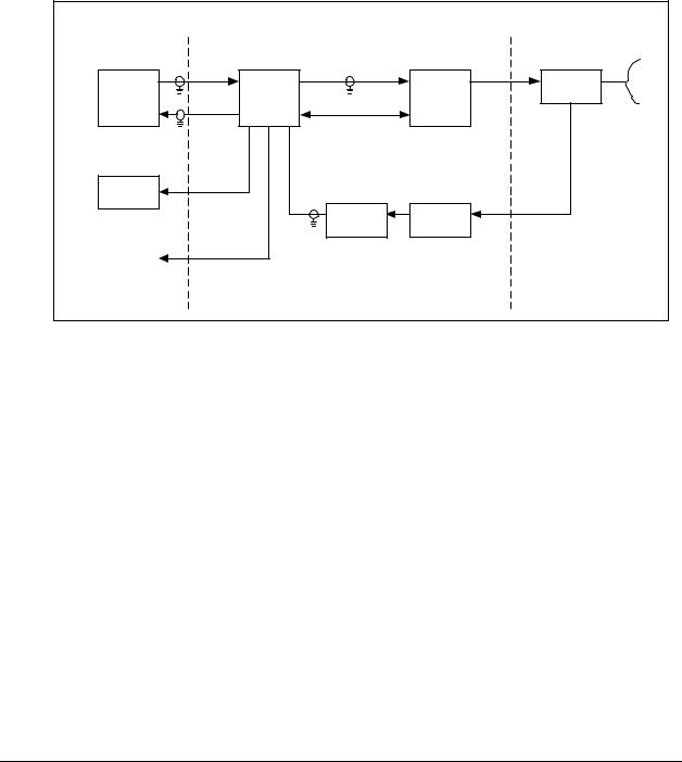
1.1.5 Single-Thread KST-2000A System
A block diagram of a single-thread, KST-2000A system is shown in Figure 1-3.
Note: The modem, the remote M&C, OMT, and the antenna are not part of the
KST-2000A system and are shown for reference only.
Indoor Units |
|
|
Reference Only |
(Reference Only) |
|
|
|
|
|
|
|
|
|
|
Antenna |
70 or 140 MHz |
Ku-Band |
|
|
TX |
TX |
Ku-Band |
OMT |
Modem |
Converter |
||
Unit |
HPA |
|
|
RX |
|
|
|
M&C (Power) |
|
|
|
|
|
|
|
Remote |
Ku-Band & |
|
|
M&C |
DC Power |
|
|
|
|
Ku-Band |
|
|
LNA |
TRF |
|
|
|
||
L-Band |
|
|
|
RX Monitor |
|
|
|
Figure 1-3. Single Thread KST-2000A System
The M&C remote control, whose operation is described in Chapter 3, is used to set the operating parameters of the KST-2000A/B system such as transmit and receive frequency, gain, etc.; and to monitor the operation of the system. Connection to the remote M&C is only required during setup and for interrogating the system health status.
Alternately, the keypad/display can be used to set the operating parameters of the KST2000A/B and to query the system for faults. Connection to a remote terminal is not required for the keypad/display to function, as the keypad/display is totally independent of the remote control system.
In the transmit (Uplink) direction, the converter unit receives a 70 MHz ± 20 MHz signal (140 MHz ± 40 MHz signal optional) at –25 to –45 dBm from a modem via a 50 or 75Ω coaxial cable. The converter’s input connector for this signal is a type N, female.
The converter unit performs a block conversion (non-inverted sense) first to S-Band, then to Ku-Band. The exact frequency output and power level are set by the user via the remote M&C or keypad/display. The converter output is coupled to an HPA via a coaxial cable with a 50Ω, female, type N connector at the converter output.
1–6
KuBand Satellite Transceiver |
Revision 9 |
Introduction |
MN/KST2000AB.IOM |
The HPA receives the Ku-Band input from the converter and amplifies it to the user-selected level.
For KST-2000A/B SSPAs of ≤ 8 Watts, prime power is supplied by the converter via the M&C cable, while SSPAs > 8 Watts require a separate power source. The output power of the SSPA is set by the user via the remote M&C or keypad, and this output is connected to the feed of the antenna via WR-75 waveguide.
In the receive (Downlink) direction, the received Ku-Band signal from the antenna is offset in frequency from the transmitted signal allowing rejection of the transmitted signal by the Transmit Reject Filter (TRF). The exact receive frequency is set by the user via the remote M&C, or entered using the keypad (on keypad/display equipped transceivers). The received signal is amplified in an LNA whose output is coupled to the converter’s input via a coaxial cable with type N connectors. This same cable is used to provide prime power (+15 VDC) to the LNA.
The converter unit performs a block down conversion (non-inverted sense) first to L-Band, then to 70 MHz (or 140 MHz if that option was ordered). An output is provided at L-Band (950 to 1700 MHz) to monitor the received signal. This is particularly useful during set up and fault finding.
1–7
KuBand Satellite Transceiver |
Revision 9 |
Introduction |
MN/KST2000AB.IOM |
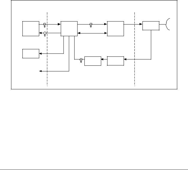
1.1.6 Single-Thread KST-2000B System
A block diagram of the KST-2000B, single-thread Ku-Band system is shown in Figure 1-4. The operation of KST-2000B system is identical to the KST-2000A system described in section 1.1.3 except in the receive (downlink) portion.
With the KST-2000B system, a LNB replaces the LNA and the block down converter from Ku-Band to L-Band in the converter unit. In this configuration, the LNB sets the received frequency range. The LNB to converter cable carries the LNB’s L-Band output, LNB prime power (+15 VDC) and a 10 MHz reference signal from the converter to the LNB.
Indoor Units |
|
|
Reference Only |
(Reference Only) |
|
|
|
|
|
|
|
|
|
|
Antenna |
70 or 140 MHz |
Ku-Band |
|
|
TX |
TX |
Ku-Band |
OMT |
Modem |
Converter |
||
Unit |
HPA |
|
|
RX |
|
|
|
M&C (Power) |
|
|
|
|
|
|
|
Remote |
L-Band, |
|
|
DC Power & |
|
|
|
M&C |
10 MHz Ref. |
|
Ku-Band |
|
LNB |
TRF |
|
|
|
||
L-Band |
|
|
|
RX Monitor |
|
|
|
Figure 1-4. Single Thread KST-2000B Block Diagram
1–8
KuBand Satellite Transceiver |
Revision 9 |
Introduction |
MN/KST2000AB.IOM |
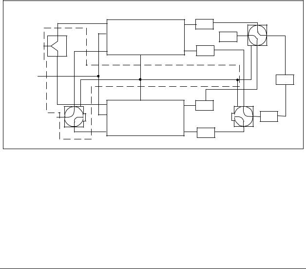
1.1.7 Redundant System
A block diagram of a redundant KST-2000A system is shown in Figure 1-5. For the KST-2000B, LNBs replace the LNAs. The KST-2000A/B contains all the logic and circuitry to sense the need to switch channels and to drive the RF switches.
The basic operation of the redundant system is identical to the single thread except that two independent TX and RX channels are provided. Initial selection of TX and RX channels is via the remote M&C or keypad.
During operation, and when a fault is detected in one channel, an automatic switchover to the other channel occurs. The RJU-2000 provides IF I/O selection and converter interface connections.
|
TX IF |
|
TX RF |
HPA |
|
REMOTE C0NVERTER UNIT |
LOAD |
||
TX IF |
RX IF |
|
|
LNA |
|
1 : 1 |
RX RF |
||
REMOTE |
|
|
RJU-2000 |
|
M&C |
|
|
|
OMT |
|
TX IF |
1 : 1 |
TX RF |
HPA |
RX IF |
REMOTE C0NVERTER UNIT |
TRF |
||
|
RX IF |
|
RX RF |
LNA |
Figure 1-5. Redundant KST-2000A System Block Diagram
1–9

KuBand Satellite Transceiver |
Revision 9 |
Introduction |
MN/KST2000AB.IOM |
1.2 Specifications
The basic KST-2000A/B specifications are listed in this section.
Table 1-2 |
Converter Unit Specification |
Table 1-3 |
System Transmit Characteristics |
Table 1-4 |
LNA Characteristics |
Table 1-5 |
LNB Characteristics |
Table 1-6 |
SSPA Characteristics |
Table 1-2. Converter Unit Specifications
Converter Transmit Characteristics |
|
|
|
|
Output Frequency |
13.75 to 14.5 GHz in 1 MHz steps |
|
||
Input Frequency |
50 to 90 MHz (100 to 180 MHz optional) |
|
||
Input Power Level |
–25 to –45 dBm operational |
|
||
|
–10 dBm survival |
|
|
|
Gain |
42 dB nominal at mid-range user |
|
||
|
attenuation setting |
|
|
|
User Attenuation Range |
0 to 20 dB in 1 dB steps |
|
||
Power Output at 1 dB Compression |
+ 15 dBm minimum |
|
|
|
Transmit Phase Noise |
Exceeds IESS 308/309 requirements |
|
||
Converter Receive |
Characteristics |
|
|
|
Input Frequency |
KST-2000A |
|
KST-2000B |
|
|
10.95 to 12.75 |
|
950 to 1700 MHz |
|
|
GHz |
|
|
|
Output Frequency |
50 to 90 MHz (100 to |
180 MHz optional) |
|
|
Gain |
45 dB maximum |
|
|
|
User Attenuation Range |
0 to 20 dB in 1 dB steps |
|
||
Gain Variation with Frequency |
|
|
|
|
(at a fixed temperature) |
2.0 dB peak-to-peak |
|
|
|
Any 40 MHz band |
|
|
||
Entire operating band |
3.0 dB peak-to-peak |
|
|
|
Power Output at 1 dB Compression |
+16 dBm minimum |
|
|
|
Power Output Stability over |
4.0 dB peak-to-peak |
|
|
|
Temperature (at a fixed frequency) |
|
|
|
|
Phase Noise |
Exceeds IESS 308/309 requirements |
|
||
Spurious Signals |
–50 dBc at –5 dBm output |
|
||
Signal Related |
|
|||
|
–35 dBc at <250 kHz from carrier |
|
||
Non-Signal Related |
–87 dBm max referenced to converter |
|
||
|
input for the KST-2000A |
|
||
|
–126 dBm max referenced to the LNB |
|
||
|
input for the KST-2000B |
|
||
Third Order Products |
–33 dBc for two carriers each at +6 dBm |
|
||
Auxiliary Output Monitor |
950 to 1700 MHz |
|
|
|
Frequency |
|
|
||
Gain |
20 dB relative to carrier input |
|
||
Connector |
Type N, female, 50Ω |
|
|
|
1–10

KuBand Satellite Transceiver |
Revision 9 |
Introduction |
MN/KST2000AB.IOM |
Table 1-2. Converter Unit Specifications (Continued)
General Converter Characteristics (Continued)
Prime Power |
85 to 264 VAC, 47 to 63 Hz, <200 W(Optional |
|
–48 VDC input) |
Keypad/Display Interface |
Weatherproof 16 character LED display with |
|
Up (S), Down (T), Left (W ), Right ( X), |
|
[Clear] and [Enter] pushbuttons |
Serial Data Interface (User |
EIA-232, EIA-485, or EIA-422 half duplex |
Selectable) |
|
Serial Data Baud (User Selectable) |
300, 600, 1200, 2400, 4800, 9600, 19200 |
Discrete Alarm Outputs |
Form “C” Relay Contacts |
Uplink Summary Alarm |
|
Downlink Summary Alarm |
Form “C” Relay Contacts |
System Summary Alarm |
Form “C” Relay Contacts |
External LED Indicators |
Prime Power On/TX RF ON |
|
Summary Fault |
IF Input/Output Connectors |
Type N Female, 50Ω |
TX Output/RX Input Connectors |
Type N Female, 50Ω |
Size |
21.75 H x 8.25W x 8.00D inches |
|
(55.2H x 20.95W x 20.32D cm) |
Weight |
33 lbs. (16 kg) |
Temperature |
–40 to +550C (-40 to +1310F) operational |
|
–50 to +750C (–67 to +1670F) survival |
Table 1-3. System Transmit Characteristics (with SSPAs of ≤ 40W)
Parameter |
|
Characteristics |
|
Gain Stability over temperature, AGC on, |
|
|
|
fixed frequency |
|
2.0 dB peak-to-peak |
|
Gain variation with frequency |
|
2.0 dB peak-to-peak |
|
70 ± 20 MHz |
|
|
|
140 ± 40 MHz |
|
3.0 dB peak-to-peak |
|
Spurious signals |
|
–50 dBc at 6 dB below P1 dB |
|
Signal related |
|
|
|
< 250 kHz |
|
–35 dBc at 6 dB below P1 dB |
|
Non-signal related |
|
–24 dBm/4 kHz for 2W unit |
|
|
|
–21 dBm/4 kHz for 4W unit |
|
|
|
–18 dBm/4 kHz for 8W unit |
|
|
|
–15 dBm/4 kHz for 16W unit |
|
|
|
–13 dBm/4 kHz for 25W unit |
|
|
|
–13 dBm/4 kHz for 32W unit |
|
|
|
–12 dBm/4 kHz for 40W unit |
|
1–11

KuBand Satellite Transceiver |
Revision 9 |
Introduction |
MN/KST2000AB.IOM |
|
Table 1-4. LNA Characteristics |
|
|
|
|
|
|
|
|
LNA Specification |
|
Input VSWR |
|
1.25:1 max. |
|
Output VSWR |
|
1.25:1 max |
|
Gain Flatness: |
|
± 2.0 dB/full band |
|
10.95 to 12.75 GHz |
|
|
|
|
|
± 0.50 dB/40 MHz |
|
10.95 to 11.7 GHz |
|
± 1.5 dB/full band |
|
|
|
± 0.25 dB/40 MHz |
|
11.7 to 12.2 GHz |
|
± 1.5 dB/full band |
|
|
|
± 0.25 dB/40 MHz |
|
12.25 to 12.75 GHz |
|
± 1.5 dB/full band |
|
|
|
± 0.25 dB/40 MHz |
|
Gain vs. Temperature |
|
± 1.5 dB Max. |
|
Operating Temperature |
|
-40 to +60°C (–40 to + 140°F) |
|
1 dB Gain Comp. Pt. |
|
+10 dBm |
|
|
|
+8 dBm or +20 dBm (optional) |
|
Third Order Intercept Point |
|
+20 dBm |
|
|
|
+18 dBm or +30 dBm (optional) |
|
Group Delay: |
|
0.01 ns/MHz |
|
Linear |
|
|
|
Parabolic |
|
0.001 ns/MHz2 |
|
Ripple |
|
0.1 ns/peak-to-peak |
|
Power Connector |
|
Powered by the KSAT through the coax |
|
RF Input W/G |
|
WR-75 Cover |
|
Input Power, Nominal |
|
+12 to +24 VDC at 100 mA |
|
|
Table 1-5. LNB Characteristics |
|
|
|
LNB Characteristics |
Frequency |
10.95 to 11.70 GHz |
|
11.70 to 12.20 GHz |
|
12.25 to 12.75 GHz |
Gain @ 25°C |
55 dB minimum, 60 dB typical |
1 dB Gain Comp. PT. |
+ 10 dBm, minimum |
Noise Figure @ 25°C |
0.9 dB, typical |
RF Input Waveguide |
WR-75 |
Input Power |
+ 15 V, 400 mA maximum |
Output |
Type N female, 50Ω |
Operating Temperature |
–40 to +55°C (–40 to 131°F) |
Operating Humidity |
0 to 100% RH |
Storage Temperature |
–50° to +80°C (–58 to +176°F) |
Size |
2.5W x 5.7L x 1.6H inches (approximately) |
|
(6.5W x 14.5L x 4H cm) |
Weight |
< 2 lbs. (< 0.9 kg) |
1–12

KuBand Satellite Transceiver |
Revision 9 |
Introduction |
MN/KST2000AB.IOM |
Table 1–6. SSPA Characteristics
Parameter |
|
2W SSPA |
|
|
4W SSPA |
|
|
8W SSPA |
|
|
16W SSPA |
|
|
25W SSPA |
|
|
32W SSPA |
|
|
40W SSPA |
|
80W SSPA |
Frequency |
|
13.75 to |
|
|
13.75 to |
|
|
13.75 to |
|
|
13.75 to |
|
|
13.75 to |
|
|
13.75 to |
|
|
13.75 to |
|
|
Range |
|
14.5 GHz |
|
|
14.5 GHz |
|
|
14.5 GHz |
|
|
14.5 GHz |
|
|
14.5 GHz |
|
|
14.5 GHz |
|
|
14.5 GHz |
|
|
|
|
(See Note 1) |
|
|
|
|
|
|
|
|
|
|
|
|
|
|
|
|
|
|
|
|
Power output at 1 dB |
|
|
|
|
|
|
|
|
|
|
|
|
|
|
|
|
|
|
|
|
|
|
Compression at 250 C: |
|
+ 33 dBm |
|
|
+ 36 dBm |
|
|
+ 39 dBm |
|
|
+ 42 dBm |
|
|
+ 44 dBm |
|
|
+ 45 dBm |
|
|
+ 46 dBm |
|
|
Guaranteed |
|
|
|
|
|
|
|
|
|
|
|
|
|
|
|
|||||||
Third Order Intermodulation |
|
+ 41 dBm |
|
|
+ 44 dBm |
|
|
+ 47 dBm |
|
|
+ 50 dBm |
|
|
+ 52 dBm |
|
|
+ 53 dBm |
|
|
+ 54 dBm |
|
|
|
|
(Intercept pt) |
|
|
(Intercept pt) |
|
|
(Intercept pt) |
|
|
(Intercept pt) |
|
|
(Intercept pt) |
|
|
(Intercept pt) |
|
|
(Intercept pt) |
|
|
Gain (Nominal) |
|
27 dB |
|
|
30 dB |
|
33 dB |
|
38 dB |
|
40 dB |
|
41 dB |
|
44 dB |
|
|
|||||
Gain Variation with |
|
2.0 dB p-p |
|
|
2.0 dB p-p |
|
|
2.0 dB p-p |
|
|
2.0 dB p-p |
|
|
2.0 dB p-p |
|
|
2.0 dB p-p |
|
|
2.0 dB p-p |
|
|
Temperature |
|
|
|
|
|
|
|
|
|
|
|
|
|
|
|
|
|
|
|
|
|
|
Input Connector |
Type N, |
|
|
Type N, |
|
|
Type N, |
|
|
Type N, |
|
|
Type N, |
|
|
Type N, |
|
|
Type N, |
|
|
|
|
Female, 50Ω |
|
|
Female, 50Ω |
|
|
Female, 50Ω |
|
|
Female, 50Ω |
|
|
Female, 50Ω |
|
Female, 50Ω |
|
|
Female, 50Ω |
|
|
||
Output Connector |
WR-75 |
|
|
WR-75 |
|
|
WR-75 |
|
|
WR-75 |
|
|
WR-75 |
|
|
WR-75 |
|
|
WR-75 |
|
|
|
|
|
W/G flange |
|
|
W/G flange |
|
|
W/G flange |
|
|
W/G flange |
|
|
W/G flange |
|
|
W/G flange |
|
|
W/G flange |
|
|
Input Power |
+9.75 VDC |
|
|
+9.75 VDC |
|
|
+9.75 VDC |
|
|
85-264 VAC, |
|
|
85-264 VAC, |
|
85-264 VAC |
|
85-264 VAC |
|
Refer to |
|||
|
from |
|
|
from converter |
|
|
from |
|
|
47-63 Hz |
|
|
47-63 Hz |
|
47-63 Hz |
|
47-63 Hz |
|
amplifier |
|||
|
|
converter |
|
|
(36W) |
|
|
converter |
|
|
(180W), |
|
|
(360W) |
|
(380W) |
|
(390W) |
|
documentation |
||
|
(30W) |
|
|
|
|
|
(90W) |
|
|
Optional –36 |
|
|
Optional –36 |
|
Optional –36 |
|
Optional –36 |
|
|
|||
|
|
|
|
|
|
|
|
|
|
|
to -72 VDC |
|
|
to -72 VDC |
|
|
to -72 VDC |
|
|
to -72 VDC |
|
|
Weight |
5 lb (2.3 kg) |
|
8 lb (3.7 kg) |
|
9 lb (4.0 kg) |
|
24 lb (11 kg) |
|
47 lb (21 kg) |
|
52 lb (21 kg) |
|
52 lb (21 kg) |
|
|
|||||||
Notes:
1.Optional: 14.0 to 14.5 GHz.
2.Optional: 13.75 to 14.5 GHz.
1–13

KuBand Satellite Transceiver |
Revision 9 |
Introduction |
MN/KST2000AB.IOM |
NOTES:
1–14

Chapter 2. INSTALLATION
This chapter provides system equipment and external connections information for both single thread and redundant systems. Refer to Appendix C (single-thread equipment) and Appendix D (redundant equipment) for installation procedures specific to particular mounting applications.
2.1.Single-Thread System Components
The standard components delivered with a single-thread system include:
QTY |
Description |
|
1 |
Base converter unit |
|
1 |
HPA (no HPA necessary for the +15dBm requirement) |
|
1 |
LNA (KST-2000A system) or LNB (KST-2000B system) |
|
As Required |
12ft (3.66m) Prime power cables for all converter units and applicable |
|
|
amplifiers |
|
As Required |
5ft (1.52m) Interlink cabling |
|
As Required |
Mounting hardware for a spar mounted offset antenna. |
(see |
|
Note) |
|
Note: Antenna type shall be indicated when ordering the KST-2000A/B unit.
2–1

Ku-Band Satellite Transceiver |
Revision 9 |
Installation |
MN/KST2000AB.IOM |
2.2.Redundant System Components
The standard delivered components included with a redundant system are:
QTY |
Description |
|
2 |
Base converter units |
|
2 |
HPA (no HPA necessary for the +15dBm requirement) |
|
2 |
LNA (KST-2000A system) or LNB (KST-2000B system) |
|
As Required |
12ft (3.66m) Prime power cables for all converter units and applicable amplifiers |
|
1 |
RJU-2000 switch junction box |
|
As Required |
Interlink cabling from the base converters to the RJU-2000 switch junction box |
|
1 |
15ft (4.57m) Interlink cable for the RX 1:1 waveguide LNA assembly (mounted directly to the |
|
|
OMT) |
|
1 |
10ft (3.05m) Interlink cable for the TX 1:1 waveguide HPA assembly (TX switching for |
|
|
+15dBm 1:1 system is provided via coaxial switch) |
|
1 |
3ft (1m) Flexible waveguide (connects the output of TX switch to the TX port of the OMT) |
|
As Required |
Mounting hardware for a spar mounted offset antenna. |
(see Note) |
1 |
M&C mating connector |
|
Note: Antenna type shall be indicated when ordering the KST-2000A/B unit.
2–2
Loading...