


CDM-600/600L
Open Network Satellite Modem (2.4 kbps – 20 Mbps) CDM-600 – 70/140 MHz (Firmware Version 2.2.6 or higher)
CDM-600L – L-Band (Firmware Version 1.5.0 or higher)
Installation and Operation Manual
(see New in this Release – Section 1.4)
Note: This manual incorporates data for the CDM-600 and CDM-600L Manuals
IMPORTANT NOTE: The information contained in this document supersedes all previously published information regarding this product. Product specifications are subject to change without prior notice.
Part Number MN/CDM600L.IOM |
Revision 3 |
Errata Page 1 of 4
Errata A
Comtech EF Data Documentation Update
Subject: |
Update CDM-600/L Flash Upgrade Procedure |
Date: |
March 26, 2010 |
Original Manual Part |
MN/CDM600L.IOM Rev 3 |
Number/Rev: |
|
Errata Number/ |
ER-MNCDM600L.EA3 |
Agile Document ID: |
|
Agile CO Number: |
C11327 |
Comments: |
Affected manual page content will be updated, as indicated below, |
|
upon next formal manual revision. |
Affected content: |
Chapter 4 pages 4-2 and 4-3. |
|
Sect. 4.2 in Chapter 4 is superseded in its entirety with the pages |
|
provided in this Errata. |
AGILE DOC ID ER-MNCDM600L.EA3 THIS DOCUMENT IS NOT SUBJECT TO REVISION/UPDATE! AGILE C11327

Errata Page 2 of 4
This page is intentionally blank.
AGILE DOC ID ER-MNCDM600L.EA3 THIS DOCUMENT IS NOT SUBJECT TO REVISION/UPDATE! AGILE C11327
Errata Page 3 of 4
AGILE DOC ID ER-MNCDM600L.EA3 THIS DOCUMENT IS NOT SUBJECT TO REVISION/UPDATE! AGILE C11327

Errata Page 4 of 4
AGILE DOC ID ER-MNCDM600L.EA3 THIS DOCUMENT IS NOT SUBJECT TO REVISION/UPDATE! AGILE C11327

CDM-600/600L
Open Network Satellite Modem (2.4 kbps – 20 Mbps)
CDM-600 – 70/140 MHz (Firmware Version 2.2.6 or higher) CDM-600L – L-Band (Firmware Version 1.5.0 or higher)
Installation and Operation Manual
(see New in this Release – Section 1.4)
Note: This manual incorporates data for the CDM-600 and CDM-600L Manuals
Part Number MN/CDM600L.IOM Revision 3 June 25, 2009
Copyright © 2009 Comtech EF Data. All rights reserved. Printed in the USA. Comtech EF Data, 2114 West 7th Street, Tempe, Arizona 85281 USA, 480.333.2200, FAX: 480.333.2161
This page is intentionally blank.

|
Table of Contents |
|
TABLE OF CONTENTS .............................................................................................................. |
III |
|
TABLES.................................................................................................................................... |
XIII |
|
FIGURES .................................................................................................................................. |
XIII |
|
PREFACE.................................................................................................................................. |
XV |
|
About this Manual .................................................................................................................................... |
xv |
|
About the Revision Level and Information Provided in this Manual ..................................................... |
xv |
|
Reporting Comments or Suggestions Concerning this Manual .............................................................. |
xv |
|
Conventions and References ................................................................................................................... |
xvi |
|
Metric Conversion ................................................................................................................................. |
xvi |
|
Cautions and Warnings .......................................................................................................................... |
xvi |
|
Recommended Standard Designations................................................................................................... |
xvi |
|
Electrical Safety ....................................................................................................................................... |
xvi |
|
Fuses ..................................................................................................................................................... |
xvii |
|
Environmental....................................................................................................................................... |
xvii |
|
Installation............................................................................................................................................. |
xvii |
|
EMC (Electromagnetic Compatibility)................................................................................................ |
xviii |
|
Warranty Policy....................................................................................................................................... |
xix |
|
Limitations of Warranty.......................................................................................................................... |
xx |
|
Exclusive Remedies ................................................................................................................................ |
xx |
|
Customer Support.................................................................................................................................... |
xxi |
|
Online Customer Support ...................................................................................................................... |
xxi |
|
CHAPTER 1. INTRODUCTION ............................................................................................. |
1–1 |
|
1.1 |
Overview ...................................................................................................................................... |
1–1 |
1.1.1 |
Standard Features.................................................................................................................. |
1–1 |
|
CDM-600/600L Common Features .............................................................................. |
1–2 |
|
CDM-600L Features ...................................................................................................... |
1–2 |
|
CDM-600 Features......................................................................................................... |
1–2 |
1.2 |
Functional Description ............................................................................................................... |
1–3 |
1.3 |
Features........................................................................................................................................ |
1–5 |
1.3.1 |
Physical Description ............................................................................................................. |
1–5 |
1.3.2 |
Compatibility ........................................................................................................................ |
1–5 |
1.3.3 |
Major Assemblies ................................................................................................................. |
1–5 |
iii

CDM-600/600L Open Network Satellite Modem |
Revision 3 |
Table of Contents |
MN/CDM600L.IOM |
1.3.4 |
|
Dimensional Envelopes......................................................................................................... |
1–6 |
1.3.5 |
|
Physical Features .................................................................................................................. |
1–8 |
1.3.5.1 |
Front Panel ........................................................................................................................ |
1–8 |
|
1.3.5.2 |
Rear Panel ......................................................................................................................... |
1–9 |
|
1.3.6 |
|
Hardware Options ............................................................................................................... |
1–10 |
1.3.6.1 |
CDM-600L Hardware Option......................................................................................... |
1–10 |
|
1.3.6.2 |
CDM-600 Hardware Options.......................................................................................... |
1–10 |
|
1.3.7 |
|
Data Interfaces .................................................................................................................... |
1–12 |
1.3.8 |
|
Verification ......................................................................................................................... |
1–12 |
1.3.9 |
|
AUPC.................................................................................................................................. |
1–12 |
1.3.10 |
EDMAC .............................................................................................................................. |
1–12 |
|
1.3.11 |
Flash Upgrading Modem Firmware.................................................................................... |
1–13 |
|
1.3.12 |
Fully Accessible System Topology (FAST) ....................................................................... |
1–13 |
|
|
|
FAST System Theory.................................................................................................. |
1–13 |
|
|
FAST Implementation................................................................................................. |
1–13 |
|
|
FAST Accessible Options........................................................................................... |
1–14 |
1.3.13 |
Supporting Hardware and Software.................................................................................... |
1–15 |
|
|
|
SatMac Complete Systems Operation......................................................................... |
1–15 |
|
|
Redundancy Applications ............................................................................................ |
1–15 |
|
|
ODU Interoperability via FSK / EDMAC.................................................................... |
1–15 |
1.4 |
New in this Release.................................................................................................................... |
1–17 |
|
1.4.1 |
|
CDM-600L Modem Firmware Release Notes .................................................................... |
1–17 |
|
|
Release Ver. 1.5.0 (7/9/08) ......................................................................................... |
1–17 |
1.4.2 |
|
CDM-600 Modem Firmware Release Notess..................................................................... |
1–17 |
|
|
Release Ver. 2.2.6 (6/26/08) ....................................................................................... |
1–17 |
1.5 |
Summary of Specifications....................................................................................................... |
1–18 |
|
1.5.1 |
|
Modulator............................................................................................................................ |
1–18 |
1.5.2 |
|
Demodulator ....................................................................................................................... |
1–21 |
1.5.3 |
|
Data Interfaces .................................................................................................................... |
1–25 |
1.5.4 |
|
Automatic Uplink Power Control (AUPC)......................................................................... |
1–26 |
1.5.5 |
|
Data Rate Ranges................................................................................................................ |
1–26 |
1.5.6 |
|
Framing Summary .............................................................................................................. |
1–27 |
1.5.7 |
|
Miscellaneous ..................................................................................................................... |
1–27 |
1.5.8 |
|
Approvals............................................................................................................................ |
1–28 |
1.5.9 |
|
AGC Voltage ...................................................................................................................... |
1–28 |
CHAPTER 2. INSTALLATION .............................................................................................. |
2–1 |
||
2.1 |
Unpacking.................................................................................................................................... |
2–1 |
|
2.2 |
Mounting...................................................................................................................................... |
2–2 |
|
2.2.1 |
|
Optional Rear-Mounting Support Brackets .......................................................................... |
2–2 |
2.3 |
Configuration .............................................................................................................................. |
2–3 |
|
2.4 |
Select Internal IF Loop............................................................................................................... |
2–4 |
|
2.5 |
Connect External Cables............................................................................................................ |
2–4 |
|
iv
CDM-600/600L Open Network Satellite Modem |
Revision 3 |
Table of Contents |
MN/CDM600L.IOM |
CHAPTER 3. REAR PANEL CONNECTOR PINOUTS ........................................................ |
3–1 |
|||
3.1 |
|
Connector Overview ................................................................................................................... |
3–1 |
|
3.2 |
|
IF Connections ............................................................................................................................ |
3–3 |
|
3.2.1 |
J1 Rx IF Connectors.............................................................................................................. |
3–3 |
||
3.2.2 |
J2 Tx IF Connectors.............................................................................................................. |
3–3 |
||
3.3 |
|
Terrestrial Data Connections..................................................................................................... |
3–4 |
|
3.3.1 |
P3A Overhead Data Connector, DB-25M ............................................................................ |
3–4 |
||
3.3.2 |
P3B Data Interface Connector, DB-25F ............................................................................... |
3–5 |
||
3.3.3 |
P4A Audio Connector, DB-9F.............................................................................................. |
3–6 |
||
3.3.4 |
G.703 Connectors ................................................................................................................. |
3–6 |
||
|
3.3.4.1 P7 Balanced G.703 Interface Connector, DB-15F............................................................ |
3–6 |
||
|
|
3.3.4.1.1 T1/E1 RJ-48 Connection via P7 Balanced G.703 Interface Connector................................ |
3–7 |
|
|
3.3.4.2 |
J10A IDI, J11A DDO Connectors, 75Ω BNC ................................................................. |
3–7 |
|
|
3.3.4.3 J10B Rx and J11B Tx Unbalanced G.703 Connectors, 75Ω BNC ................................... |
3–8 |
||
3.4 |
|
Utility Connections...................................................................................................................... |
3–8 |
|
3.4.1 |
P6 Aux Serial Receptacle, USB Type ‘B’ ............................................................................ |
3–8 |
||
3.4.2 |
J9 Ext Clk (CDM-600L) / Ext Ref (CDM-600), 50Ω BNC.................................................. |
3–8 |
||
3.4.3 |
P4B Remote Control Interface Connector, DB-9M.............................................................. |
3–9 |
||
3.4.4 |
P5A IDR Alarms Connector, DB-15F .................................................................................. |
3–9 |
||
3.4.5 |
P5B Alarms Connector, DB-15M....................................................................................... |
3–10 |
||
3.4.6 |
J12 Ext Ref (CDM-600L) / Ext Freq Ref (CDM-600) ....................................................... |
3–11 |
||
3.5 |
Power / Ground Connections................................................................................................... |
3–11 |
||
3.5.1 |
Alternating Current (AC) Power Connector (Standard) ..................................................... |
3–11 |
||
3.5.2 |
Direct Current (DC) Power Connector (Optional, CDM-600L only)................................. |
3–12 |
||
3.5.3 |
Ground Connector............................................................................................................... |
3–12 |
||
CHAPTER 4. |
FLASH UPGRADING...................................................................................... |
4–1 |
||
4.1 |
Flash Updating via Internet ....................................................................................................... |
4–1 |
||
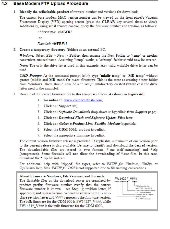
4.2 |
Ethernet FTP Upload Procedure............................................................................................... |
4–2 |
||
CHAPTER 5. FRONT PANEL OPERATION......................................................................... |
5–1 |
|||
5.1 |
|
Description................................................................................................................................... |
5–1 |
|
5.1.1 |
Front Panel LED Indicators .................................................................................................. |
5–2 |
||
5.1.2 |
Front Panel Keypad............................................................................................................... |
5–3 |
||
5.1.3 |
Front Panel Vacuum Fluorescent Display (VFD)................................................................. |
5–3 |
||
5.2 |
|
Opening Screen ........................................................................................................................... |
5–4 |
|
5.3 |
|
SELECT: (Main) Menu.............................................................................................................. |
5–6 |
|
5.4 |
|
(SELECT:) CONFIGURATION ............................................................................................... |
5–7 |
|
v

CDM-600/600L Open Network Satellite Modem |
Revision 3 |
Table of Contents |
MN/CDM600L.IOM |
5.4.1 |
|
CONFIG: ALL...................................................................................................................... |
5–8 |
5.4.2 |
|
CONFIG: MODE.................................................................................................................. |
5–8 |
5.4.3 |
|
CONFIG: TX ........................................................................................................................ |
5–9 |
5.4.3.1 CONFIG: Tx Æ TX-IF ..................................................................................................... |
5–9 |
||
5.4.3.2 CONFIG: TX Æ POWER .............................................................................................. |
5–10 |
||
5.4.3.3 CONFIG: TX Æ ENCODER.......................................................................................... |
5–12 |
||
5.4.3.4 CONFIG: TX Æ MOD (Modulation)............................................................................. |
5–13 |
||
5.4.3.5 CONFIG: TX Æ DATA ................................................................................................. |
5–13 |
||
5.4.3.6 CONFIG: TX Æ SCRAMBLER .................................................................................... |
5–14 |
||
5.4.4 |
|
CONFIG: RX ...................................................................................................................... |
5–14 |
5.4.4.1 CONFIG: RX Æ RX-IF.................................................................................................. |
5–15 |
||
5.4.4.2 CONFIG: RX Æ DECODER ......................................................................................... |
5–16 |
||
5.4.4.3 CONFIG: RX Æ DEMOD (Demodulation) ................................................................... |
5–17 |
||
5.4.4.4 CONFIG: RX Æ DATA ................................................................................................. |
5–17 |
||
5.4.4.5 CONFIG: RX Æ DESCRAMBLER............................................................................... |
5–18 |
||
5.4.4.6 CONFIG: RX Æ EbNo................................................................................................... |
5–18 |
||
5.4.5 |
|
CONFIG: CLOCKS............................................................................................................ |
5–19 |
5.4.5.1 CONFIG: CLOCKS Æ TX-CLOCK.............................................................................. |
5–19 |
||
5.4.5.2 CONFIG: CLOCKS Æ RX-BUFFER/CLOCK ............................................................. |
5–20 |
||
5.4.5.3 CONFIG: CLOCKS Æ EXTERNAL BASEBAND CLOCK........................................ |
5–21 |
||
5.4.5.4 CONFIG: CLOCKS Æ EXT-FREQ-REF (CDM-600 ONLY) ...................................... |
5–21 |
||
5.4.5.5 CONFIG: CLOCKS Æ INT-REF (CDM-600 ONLY)................................................... |
5–21 |
||
5.4.6 CONFIG: D&I (Drop & Insert) .......................................................................................... |
5–22 |
||
5.4.6.1 CONFIG: D&I Æ LOOP................................................................................................ |
5–22 |
||
5.4.6.2 CONFIG: D&I Æ DRP-TYPE or INS-TYPE ................................................................ |
5–22 |
||
5.4.6.3 CONFIG: D&I Æ DROP or INSERT CHAN/TS (Channel Timeslots)......................... |
5–23 |
||
5.4.7 CONFIG: FREQ-REF (CDM-600L ONLY) ...................................................................... |
5–23 |
||
5.4.8 |
|
CONFIG: EDMAC ............................................................................................................. |
5–23 |
5.4.9 |
|
CONFIG: MISC.................................................................................................................. |
5–24 |
5.4.9.1 CONFIG: MISC Æ G.703-LINE-CODE (Ternary Code).............................................. |
5–24 |
||
5.4.9.2 CONFIG: MISC Æ IDR-ESC-TYPE ............................................................................. |
5–24 |
||
5.4.9.3 CONFIG: MISC Æ ADPCM-AUDIO-VOLUME ......................................................... |
5–25 |
||
5.4.9.4 CONFIG: MISC Æ HIGH-RATE-ESC.......................................................................... |
5–25 |
||
5.4.9.5 CONFIG: Misc Æ WARM-UP (CDM-600 ONLY) ...................................................... |
5–26 |
||
5.4.10 CONFIG: REMOTE (Remote Control).............................................................................. |
5–26 |
||
5.4.10.1 CONFIG: REMOTE Æ LOCAL or REMOTE Settings............................................. |
5–27 |
||
5.4.11 |
CONFIG: MASK ................................................................................................................ |
5–28 |
|
5.4.11.1 CONFIG: MASK Æ AIS............................................................................................ |
5–28 |
||
5.4.11.2 CONFIG: MASK Æ BUFFER (Buffer Slip).............................................................. |
5–28 |
||
5.4.11.3 CONFIG: MASK Æ Rx-IF......................................................................................... |
5–28 |
||
5.4.11.4 CONFIG: MASK Æ SAT-ALM (Satellite Alarms) ................................................... |
5–29 |
||
5.4.11.5 CONFIG: MASK Æ TERR-ALM.............................................................................. |
5–29 |
||
5.4.12 CONFIG: IMPEDANCE (CDM-600 ONLY) .................................................................... |
5–30 |
||
5.4.13 |
CONFIG: STATISTICS ..................................................................................................... |
5–30 |
|
5.5 |
SELECT: TEST ........................................................................................................................ |
5–31 |
|
5.6 |
SELECT: INFORMATION..................................................................................................... |
5–33 |
|
5.6.1 |
|
INFO: ALL ......................................................................................................................... |
5–33 |
5.6.2 |
|
INFO: ID............................................................................................................................. |
5–33 |
vi

CDM-600/600L Open Network Satellite Modem |
Revision 3 |
Table of Contents |
MN/CDM600L.IOM |
5.6.3 |
|
INFO: MODE ..................................................................................................................... |
5–33 |
5.6.4 |
|
INFO: TX............................................................................................................................ |
5–34 |
5.6.5 |
|
INFO: RX............................................................................................................................ |
5–35 |
5.6.6 |
|
INFO: CLOCKS ................................................................................................................. |
5–35 |
5.6.7 |
|
INFO: EDMAC................................................................................................................... |
5–36 |
5.6.8 |
|
INFO: DROP (Drop Type) ................................................................................................. |
5–36 |
5.6.9 |
|
INFO: INSERT (Insert Type) ............................................................................................. |
5–36 |
5.6.10 |
INFO: REMOTE................................................................................................................. |
5–36 |
|
5.6.11 |
INFO: ALARM-MASK...................................................................................................... |
5–36 |
|
5.6.12 |
INFO-MISC ........................................................................................................................ |
5–37 |
|
5.7 |
SELECT: MONITOR .............................................................................................................. |
5–37 |
|
5.7.1 |
MONITOR: LIVE-ALARMS............................................................................................. |
5–37 |
|
5.7.2 |
MONITOR: STORED-EVENTS........................................................................................ |
5–39 |
|
5.7.3 |
MONITOR: STATISTICS.................................................................................................. |
5–40 |
|
5.7.4 |
MONITOR: RX-PARAMS................................................................................................. |
5–41 |
|
5.7.5 |
MONITOR: AUPC-PARAM.............................................................................................. |
5–41 |
|
5.7.6 |
MONITOR: LNB (CDM-600L ONLY) ............................................................................. |
5–41 |
|
5.7.7 MONITOR: BUC (CDM-600L ONLY) ............................................................................. |
5–41 |
||
5.8 |
SELECT: STORE/LOAD ........................................................................................................ |
5–42 |
|
5.9 |
SELECT: UTILITIES .............................................................................................................. |
5–42 |
|
5.9.1 |
UTILITIES: SET-RTC ....................................................................................................... |
5–42 |
|
5.9.2 |
UTILITIES: DISPLAY-BRIGHTNESS............................................................................. |
5–43 |
|
5.9.3 |
UTILITIES: LAMP............................................................................................................. |
5–43 |
|
5.9.4 |
UTILITIES: 1:1-MANUAL-SWITCH ............................................................................... |
5–43 |
|
5.9.5 |
|
UTILITIES: EDIT-CIRCUIT-ID........................................................................................ |
5–43 |
5.10 SELECT: ODU (OUTDOOR UNIT) ...................................................................................... |
5–44 |
||
5.11 |
SELECT: FAST ........................................................................................................................ |
5–44 |
|
5.11.1 |
FAST: SET.......................................................................................................................... |
5–44 |
|
5.11.2 |
FAST: VIEW ...................................................................................................................... |
5–44 |
|
CHAPTER 6. FORWARD ERROR CORRECTION OPTIONS............................................. |
6–1 |
||
6.1 |
Introduction................................................................................................................................. |
6–1 |
|
6.2 |
Viterbi .......................................................................................................................................... |
6–1 |
|
6.3 |
Sequential..................................................................................................................................... |
6–2 |
|
6.4 |
Reed-Solomon Outer Codec....................................................................................................... |
6–3 |
|
6.5 |
Trellis Coding (FAST Option) ................................................................................................... |
6–4 |
|
6.6 |
Turbo Product Codec (Hardware Option) ............................................................................... |
6–5 |
|
6.7 |
TPC and Low Density Parity Check (LDPC) coding .............................................................. |
6–6 |
|
vii

CDM-600/600L Open Network Satellite Modem |
Revision 3 |
Table of Contents |
MN/CDM600L.IOM |
6.7.1 |
Introduction........................................................................................................................... |
6–6 |
|
6.7.2 |
LDPC versus TPC................................................................................................................. |
6–7 |
|
6.7.3 |
End-to-End Processing Delay ............................................................................................... |
6–8 |
|
6.8 |
Uncoded Operation (No FEC) ................................................................................................. |
6–11 |
|
CHAPTER 7. AUTOMATIC UPLINK POWER CONTROL (AUPC)..................................... |
7–1 |
||
7.1 |
|
Introduction................................................................................................................................. |
7–1 |
7.2 |
|
Setting AUPC Parameters.......................................................................................................... |
7–1 |
7.2.1 |
AUPC Target Eb/N0............................................................................................................... |
7–2 |
|
7.2.2 |
AUPC Max Range ................................................................................................................ |
7–2 |
|
7.2.3 |
AUPC Alarm......................................................................................................................... |
7–2 |
|
7.2.4 |
Demod Unlock ...................................................................................................................... |
7–3 |
|
7.3 |
|
Compensation Rate..................................................................................................................... |
7–3 |
7.4 |
|
Monitoring................................................................................................................................... |
7–3 |
CHAPTER 8. CLOCKING MODES AND DROP AND INSERT (D&I)................................... |
8–1 |
||
8.1 |
|
Introduction................................................................................................................................. |
8–1 |
8.2 |
|
Transmit Clocking ...................................................................................................................... |
8–1 |
8.2.1 |
Internal Clock........................................................................................................................ |
8–1 |
|
8.2.2 |
Tx Terrestrial Clock.............................................................................................................. |
8–2 |
|
8.2.3 |
Rx Loop-Timed, Rx=Tx ....................................................................................................... |
8–2 |
|
8.2.4 |
Rx Loop-Timed, Rx<>Tx (Asymmetric Loop Timing)........................................................ |
8–2 |
|
8.2.5 |
External Clock ...................................................................................................................... |
8–2 |
|
8.3 |
|
Receive Clocking ......................................................................................................................... |
8–3 |
8.3.1 |
Buffer Disabled (Rx Satellite)............................................................................................... |
8–3 |
|
8.3.2 |
Buffer Enabled, Tx=Rx (Tx Terrestrial or External Clock).................................................. |
8–3 |
|
8.3.3 |
Buffer Enabled, Rx<>Tx (Tx Terrestrial or External Clock) ............................................... |
8–3 |
|
8.4 |
|
X.21 Notes .................................................................................................................................... |
8–3 |
8.5 |
Drop and Insert (D&I) with ESC and AUPC........................................................................... |
8–6 |
|
8.6 |
|
Frame Formats............................................................................................................................ |
8–7 |
8.7 |
|
Time Slot Selection...................................................................................................................... |
8–8 |
8.8 |
Drop and Insert (D&I) Clocking ............................................................................................... |
8–9 |
|
8.9 |
|
Rx Buffer Clock = Insert (D&I only) ...................................................................................... |
8–10 |
8.10 |
|
Single-Source Multiple Modems.............................................................................................. |
8–10 |
viii

CDM-600/600L Open Network Satellite Modem |
Revision 3 |
Table of Contents |
MN/CDM600L.IOM |
CHAPTER 9. |
EDMAC CHANNEL ......................................................................................... |
9–1 |
||
9.1 |
Theory Of Operation .................................................................................................................. |
9–1 |
||
9.2 |
M&C Connection ........................................................................................................................ |
9–2 |
||
9.3 |
Setup Summary........................................................................................................................... |
9–3 |
||
CHAPTER 10. |
ESC++ ......................................................................................................... |
10–1 |
||
10.1 |
Introduction............................................................................................................................... |
10–1 |
||
10.2 |
Overhead Details....................................................................................................................... |
10–1 |
||
10.3 |
Available Baud Rates................................................................................................................ |
10–2 |
||
10.4 |
Configuration ............................................................................................................................ |
10–2 |
||
10.5 |
Effect on Eb/No performance .................................................................................................. |
10–2 |
||
CHAPTER 11. OFFSET QPSK OPERATION ..................................................................... |
11–1 |
|||
CHAPTER 12. OPEN NETWORK OPERATIONS............................................................... |
12–1 |
|||
12.1 |
Introduction............................................................................................................................... |
12–1 |
||
12.2 |
IBS .............................................................................................................................................. |
|
|
12–2 |
12.2.1 |
IBS Clock/data recovery and De-jitter................................................................................ |
12–2 |
||
12.2.2 |
IBS Framing........................................................................................................................ |
12–2 |
||
12.2.3 |
IBS Engineering Service Channel....................................................................................... |
12–2 |
||
12.2.4 |
IBS Scrambling................................................................................................................... |
12–2 |
||
12.3 |
Drop and Insert ......................................................................................................................... |
12–3 |
||
12.3.1 |
D&I Primary Data Interfaces .............................................................................................. |
12–3 |
||
12.3.2 |
D&I Framing....................................................................................................................... |
12–3 |
||
12.4 |
IDR ............................................................................................................................................. |
|
|
12–4 |
12.4.1 |
IDR Primary Data Interfaces............................................................................................... |
12–4 |
||
12.4.2 |
IDR Framing ....................................................................................................................... |
12–4 |
||
12.4.3 |
IDR Engineering Service Channel...................................................................................... |
12–5 |
||
APPENDIX A. |
CABLE DRAWINGS ...................................................................................... |
A-1 |
||
A.1 |
Introduction................................................................................................................................. |
A-1 |
||
A.1.1 |
RS-530 to RS-422/449 Data Cable ....................................................................................... |
A-2 |
||
A.1.2 |
RS-530 to V.35 Data Cable................................................................................................... |
A-3 |
||
A.1.3 |
RS-530 to V.35 Data Cable................................................................................................... |
A-4 |
||
A.1.4 |
RS-530 Conversion Cable..................................................................................................... |
A-5 |
||
A.1.5 |
Switch Programming Cable .................................................................................................. |
A-6 |
||
ix

CDM-600/600L Open Network Satellite Modem |
Revision 3 |
Table of Contents |
MN/CDM600L.IOM |
A.1.6 |
E1/T1 Adapter....................................................................................................................... |
A-7 |
|
APPENDIX B. EB/N0 MEASUREMENT ................................................................................ |
B–1 |
||
APPENDIX C. FAST ACTIVATION PROCEDURE .............................................................. |
C–1 |
||
C.1 |
Introduction................................................................................................................................ |
C–1 |
|
C.2 |
Activation Procedure ................................................................................................................. |
C–1 |
|
C.2.1 |
Serial Number ...................................................................................................................... |
C–1 |
|
C.2.2 View currently installed features ......................................................................................... |
C–1 |
||
C.2.3 |
Enter Access Codes.............................................................................................................. |
C–2 |
|
APPENDIX D. SERIAL REMOTE CONTOL......................................................................... |
D–1 |
||
D.1 |
Overview ..................................................................................................................................... |
D–1 |
|
D.2 |
RS-485 ......................................................................................................................................... |
D–1 |
|
D.3 |
RS-232 ......................................................................................................................................... |
D–2 |
|
D.4 |
Basic Protocol............................................................................................................................. |
D–2 |
|
D.5 |
Packet Structure......................................................................................................................... |
D–3 |
|
D.5.1 |
Start of Packet ...................................................................................................................... |
D–3 |
|
D.5.2 |
Target Address ..................................................................................................................... |
D–3 |
|
D.5.3 |
Address Delimiter ................................................................................................................ |
D–3 |
|
D.5.4 |
Instruction Code................................................................................................................... |
D–4 |
|
D.5.5 |
Instruction Code Qualifier ................................................................................................... |
D–4 |
|
D.5.6 |
Optional Message Arguments.............................................................................................. |
D–5 |
|
D.5.7 |
End of Packet ....................................................................................................................... |
D–5 |
|
D.6 |
Remote Commands and Queries .............................................................................................. |
D–6 |
|
|
|
Section D.6 Notes: ....................................................................................................... |
D–7 |
D.6.1 Transmit (Tx) Commands and Queries................................................................................ |
D–8 |
||
D.6.2 Receive (Rx) Commands and Queries ............................................................................... |
D–15 |
||
D.6.3 Unit Commands and Queries ............................................................................................. |
D–20 |
||
D.6.4 |
Queries ............................................................................................................................... |
D–26 |
|
D.6.5 |
Bulk Commands................................................................................................................. |
D–31 |
|
D.6.6 BUC Commands and Queries (CDM-600L ONLY) ......................................................... |
D–34 |
||
D.6.7 LNB Commands and Queries (CDM-600L ONLY).......................................................... |
D–36 |
||
D.6.8 High-Stability Reference Option Commands and Queries (CDM-600 ONLY) ................ |
D–37 |
||
APPENDIX E. ODU (CSAT-5060, KST-2000A/B) OPERATION VIA THE CDM-600.......... |
E–1 |
||
E.1 |
Introduction................................................................................................................................ |
E–1 |
|
E.2 ODU Operations via Serial Remote Control ........................................................................... |
E–2 |
||
x

CDM-600/600L Open Network Satellite Modem |
Revision 3 |
Table of Contents |
MN/CDM600L.IOM |
E.2.1 Remote Control Address Setup............................................................................................. |
E–2 |
|
E.3 ODU Operations via the CDM-600 Front Panel ..................................................................... |
E–3 |
|
E.3.1 ODU Operation – Front Panel Menu Tree (Basic) ............................................................... |
E–4 |
|
E.3.2 (SELECT:) (Main) Menu...................................................................................................... |
E–5 |
|
E.3.3 (SELECT:) ODU – Product-specific Menu Operations........................................................ |
E–5 |
|
E.3.3.1 (SELECT:) ODU (CSAT-5060 Transceiver).................................................................... |
E–8 |
|
E.3.3.1.1 ODU: ENABLE ÆSYSTEM TYPE=STANDALONE...................................................... |
E–8 |
|
E.3.3.1.2 ODU: ENABLE ÆSYSTEM TYPE=1:1............................................................................. |
E–8 |
|
|
1:1 MONITOR & CONTROL ÆODU#1 or ODU#2 .................................................. |
E–9 |
|
1:1 MONITOR & CONTROL ÆREDUNDANCY-BOX ........................................... |
E–9 |
E.3.3.1.3 COMMON ‘ODU SELECT’ SUBMENU .......................................................................... |
E–10 |
|
E.3.3.1.3.1 ODU SELECT: CONFIGURATION ................................................................ |
E–10 |
|
|
CONFIGURATION Æ TX-PARAMETERS............................................................. |
E–10 |
|
CONFIGURATION ÆTX-PARAMETERS ÆSLOPE.................................................. |
E–11 |
|
CONFIGURATION Æ RX-PARAMETERS............................................................. |
E–11 |
|
CONFIGURATION ÆRX-PARAMETERS ÆSLOPE ................................................. |
E–11 |
|
CONFIGURATION Æ LNA-PARAMETERS .......................................................... |
E–11 |
|
CONFIGURATION Æ MISCELLANEOUS............................................................. |
E–12 |
E.3.3.1.3.2 ODU SELECT: MONITOR .............................................................................. |
E–13 |
|
|
MONITOR: TRANSMIT ........................................................................................... |
E–13 |
|
MONITOR: RECEIVE ............................................................................................... |
E–13 |
|
MONITOR: MISCELLANEOUS............................................................................... |
E–13 |
|
MONITOR: POWER-SUPPLIES............................................................................... |
E–13 |
E.3.3.1.3.3 ODU SELECT: ALARMS ................................................................................ |
E–14 |
|
|
ALARMS: CURRENT-ALARMS ............................................................................. |
E–14 |
|
ALARMS: STORED-ALARMS ................................................................................ |
E–14 |
E.3.3.1.3.4 ODU SELECT: INFORMATION..................................................................... |
E–15 |
|
|
INFORMATION: MODEL ........................................................................................ |
E–15 |
|
INFORMATION: TX ................................................................................................. |
E–15 |
|
INFORMATION: RX ................................................................................................. |
E–15 |
|
INFORMATION: MISC............................................................................................. |
E–15 |
|
INFORMATION: LNA .............................................................................................. |
E–16 |
E.3.3.2 (SELECT:) ODU (KST-2000A/B Transceiver).............................................................. |
E–16 |
|
|
ODU: STANDALONE Æ KST SELECT.................................................................. |
E–16 |
E.3.3.2.1 |
KST SELECT: CONFIGURATION.................................................................................... |
E–16 |
|
CONFIGURATION Æ TX-PARAM ......................................................................... |
E–17 |
|
CONFIGURATION Æ RX-PARAM......................................................................... |
E–17 |
|
CONFIGURATION Æ RX-PARAM Æ BAND........................................................ |
E–18 |
|
CONFIGURATION Æ MISCELLANEOUS............................................................. |
E–18 |
E.3.3.2.2 |
KST SELECT: INFORMATION ......................................................................................... |
E–18 |
|
INFORMATION Æ MODEL..................................................................................... |
E–19 |
|
INFORMATION Æ TX+RX-PARAM ...................................................................... |
E–19 |
|
INFORMATION Æ MISC ......................................................................................... |
E–19 |
|
INFORMATION Æ NUMBERS ............................................................................... |
E–19 |
E.3.3.2.3 |
KST SELECT: ALARMS ..................................................................................................... |
E–20 |
APPENDIX F. |
ODU (BUC, LNB) OPERATION VIA THE CDM-600L ................................... |
F–1 |
xi

CDM-600/600L Open Network Satellite Modem |
Revision 3 |
Table of Contents |
MN/CDM600L.IOM |
F.1 |
Introduction................................................................................................................................. |
F–1 |
|
F.2 |
ODU Operations via Serial Remote Control ............................................................................ |
F–1 |
|
F.2.1 Remote Control Address Setup............................................................................................. |
F–1 |
||
F.3 |
ODU Operations via the CDM-600L Front Panel ................................................................... |
F–2 |
|
F.3.1 ODU Operation – Front Panel Menu Tree............................................................................ |
F–3 |
||
F.3.2 Front Panel Menu Operations ............................................................................................... |
F–4 |
||
F.3.3 |
SELECT: (Main) Menu ........................................................................................................ |
F–4 |
|
F.3.4 (SELECT:) ODU (Outdoor Unit) ......................................................................................... |
F–5 |
||
|
F.3.4.1 |
ODU: BUC-FSK............................................................................................................... |
F–5 |
|
F.3.4.2 |
ODU: BUC-CONFIG ....................................................................................................... |
F–6 |
|
F.3.4.3 |
ODU: BUC-LO................................................................................................................. |
F–6 |
|
F.3.4.4 |
ODU: LNB-CONFIG........................................................................................................ |
F–7 |
|
F.3.4.5 |
ODU: LNB-LO ................................................................................................................. |
F–7 |
F.3.5 |
(SELECT:) MONITOR......................................................................................................... |
F–8 |
|
|
F.3.5.1 |
MONITOR: LNB.............................................................................................................. |
F–8 |
|
F.3.5.2 |
MONITOR: BUC.............................................................................................................. |
F–8 |
APPENDIX G. BUC FSK COMMUNICATIONS (CDM-600L)............................................... |
G–1 |
||
APPENDIX H. DST SETUP (CDM-600L) ............................................................................. |
H–1 |
||
H.1 |
Overview ..................................................................................................................................... |
H–1 |
|
H.2 |
Initial Operation......................................................................................................................... |
H–1 |
|
H.2.1 Prior to Turning On Power................................................................................................... |
H–1 |
||
H.2.2 Initial Power Up – Modem Only.......................................................................................... |
H–2 |
||
H.3 |
LO, Mix, and Spectrum (Inversion) Settings........................................................................... |
H–2 |
|
H.4 |
Applying Power To The BUC ................................................................................................... |
H–3 |
|
H.5 |
Tx Side Setup.............................................................................................................................. |
H–4 |
|
H.6 |
Initial Operation of the Modem with the BUC and LNB ....................................................... |
H–5 |
|
H.6.1 |
RX Side Setup...................................................................................................................... |
H–5 |
|
APPENDIX J. KT/11202-1 STEP ATTENUATOR KIT (CDM-600L) ..................................... |
J–1 |
||
J.1 |
Introduction................................................................................................................................. |
J–1 |
|
J.2 |
Kit Installation ............................................................................................................................ |
J–1 |
|
J.3 |
Front Panel Operation................................................................................................................ |
J–3 |
|
|
|
CONFIG: TX Æ POWER ............................................................................................ |
J–3 |
|
|
CONFIG: TX Æ POWER Æ MODE Æ MANUAL ................................................... |
J–3 |
|
|
CONFIG: TX Æ POWER Æ MODE Æ MANUAL-LOW ......................................... |
J–3 |
|
|
CONFIG: TX Æ POWER Æ MODE Æ AUPC .......................................................... |
J–4 |
xii

CDM-600/600L Open Network Satellite Modem |
Revision 3 |
Table of Contents |
MN/CDM600L.IOM |
CONFIG: TX Æ POWER Æ MODE Æ CONFIG: TX Æ POWER Æ MODE Æ CONFIG: TX Æ POWER Æ MODE Æ CONFIG: TX Æ POWER Æ MODE Æ
AUPC-LOW................................................ |
J–4 |
AUPC Æ TARGET-EbNo/RANGE ........... |
J–4 |
AUPC-LOW Æ TARGET-EbNo/RANGE. J–4
AUPC/AUPC-LOW Æ ALARM/ACTION J–4
J.4 |
Remote Control Operation......................................................................................................... |
J–5 |
Tables
Table 1-1. CDM-600/600L Rear Panel Connectors.................................................................................. |
1–7 |
|
Table 3-1. Rear Panel External Connections ............................................................................................ |
3–2 |
|
Table 6-1. Viterbi Decoding Summary..................................................................................................... |
6–2 |
|
Table 6-2. Sequential Decoding Summary ............................................................................................... |
6–3 |
|
Table 6-3. Concatenated Reed-Solomon Coding Summary ..................................................................... |
6–4 |
|
Table 6-4. |
8-PSK/TCM Coding Summary ............................................................................................... |
6–5 |
Table 6-5. |
Available TPC and LDPC Modes ........................................................................................... |
6–8 |
Table 6-6. |
Turbo Product Coding Processing Delay Comparison............................................................ |
6–9 |
Table 6-7. |
Comparison of all Comtech EF Data TPC and LDPC Modes............................................... |
6–10 |
Table 6-8. TPC and LDPC Summary ..................................................................................................... |
6–10 |
|
Figures |
|
Figure 1-1. CDM-600/600L Open Network Satellite Modem (CDM-600L shown)................................ |
1–1 |
Figure 1-2. CDM-600/600L Open Network Satellite Modem Block Diagrams....................................... |
1–4 |
Figure 1-3. CDM-600L Dimensional Envelope ....................................................................................... |
1–6 |
Figure 1-4. CDM-600 Dimensional Envelope.......................................................................................... |
1–7 |
Figure 1-5. Front Panel View (CDM-600L shown).................................................................................. |
1–8 |
Figure 1-6. Rear Panel View..................................................................................................................... |
1–9 |
Figure 2-1. Optional Rear-Mounting Support Brackets Installation......................................................... |
2–3 |
Figure 3-1. CDM-600/600L Rear Panel ................................................................................................... |
3–1 |
Figure 3-2. CN-0000268 DB-15M Æ RJ-48F Adapter for T1/E1 Operation........................................... |
3–7 |
Figure 4-1. Flash Update via Internet ....................................................................................................... |
4–1 |
Figure 5-1. CDM-600/600L – Front Panel View (CDM-600L shown).................................................... |
5–1 |
Figure 5-2. CDM-600/600L – Principle Menu Tree................................................................................. |
5–5 |
Figure 5-3. Loopback Modes.................................................................................................................. |
5–32 |
Figure 6-1. Viterbi Decoding.................................................................................................................. |
6–13 |
Figure 6-2. Sequential Decoding 64 kbps.............................................................................................. |
6–14 |
Figure 6-3. Sequential Decoding 1024 kbps........................................................................................... |
6–15 |
Figure 6-4. Sequential Decoding 2048 kbps........................................................................................... |
6–16 |
Figure 6-5. Viterbi with concatenated Reed-Solomon Outer Code ........................................................ |
6–17 |
Figure 6-6. Sequential with concatenated Reed-Solomon Outer Code................................................... |
6–18 |
Figure 6-7. 8-PSK/TCM Rate 2/3 with and without concatenated Reed-Solomon Outer Code................ |
6–19 |
Figure 6-8. Comtech EF Data Turbo Product Codec Rate 3/4 QPSK/OQPSK, 8-PSK and 16-QAM ............ |
6–20 |
Figure 6-9. Comtech EF Data Turbo Product Codec Rate 7/8 QPSK/OQPSK, 8-PSK and 16-QAM ... |
6–21 |
Figure 6-10. Rate 1/2 QPSK, Rate 0.95 QPSK and Rate 0.95 8-PSK........................................................... |
6–22 |
xiii

CDM-600/600L Open Network Satellite Modem |
Revision 3 |
Table of Contents |
MN/CDM600L.IOM |
Figure 6-11. Rate 21/44 BPSK and Rate 5/16 BPSK Turbo .................................................................... |
6–23 |
Figure 6-12. 16-QAM Viterbi, Rate 3/4 and Rate 7/8 with 220,200 Reed-Solomon Outer Code ........... |
6–24 |
Figure 6-13. Differential Encoding – No FEC, No Scrambling............................................................... |
6–25 |
Figure 6-14. LDPC, Rate 1/2, BPSK, (O)QPSK...................................................................................... |
6–26 |
Figure 6-15. LDPC, Rate 2/3, (O)QPSK / 8-PSK / 8-QAM .................................................................... |
6–27 |
Figure 6-16. LDPC, Rate 3/4, (O)QPSK / 8-QAM................................................................................. |
6–28 |
Figure 6-17. LDPC, Rate 3/4, 8-PSK / 16-QAM ..................................................................................... |
6–29 |
Figure 8-1. Tx Clock Modes..................................................................................................................... |
8–4 |
Figure 8-2. Rx Clock Modes..................................................................................................................... |
8–5 |
Figure 8-3. Supported T1 and E1 Framing formats .................................................................................. |
8–7 |
Figure 8-4. Drop and Insert Clocking ....................................................................................................... |
8–9 |
Figure 8-5. Single-Source Multiple Modems (Looming) ....................................................................... |
8–10 |
Figure 8-6. Single-Source Multiple Modems (Daisy-chain)................................................................... |
8–10 |
Figure A-1. DCE Conversion Cable: RS-530 to RS-422/449 (CA/WR0049)......................................... |
A-2 |
Figure A-2. DCE Conversion Cable: RS-530 to V.35 (CA/WR0059) .................................................... |
A-3 |
Figure A-3. DCE Conversion Cable: RS-530 (CA/WR9718-1).............................................................. |
A-4 |
Figure A-4. DCE Conversion Cable: RS-530 to V.35............................................................................. |
A-5 |
Figure A-5. Switch Programming Cable.................................................................................................. |
A-6 |
Figure A-6. E1/T1 DB-15 Æ RJ-48 Adapter (CN-0000268) .................................................................. |
A-7 |
Figure E-1. CDM-600 Front Panel View.................................................................................................. |
E–3 |
Figure E-2. CDM-600 ODU Operation Principal Menu Tree .................................................................. |
E–4 |
Figure E-3. (SELECT:) ODU Æ CSAT-5060 Transceiver Menu Tree ................................................... |
E–6 |
Figure E-4. (SELECT:) ODU Æ KST-2000A/B Transceiver Menu Tree................................................ |
E–7 |
Figure F-1. CDM-600L Front Panel View................................................................................................ |
F–2 |
Figure F-2. CDM-600L ODU Operation Principal Menu Tree ................................................................ |
F–3 |
Figure J-1. KT/11202-1 External 20 dB Step Attenuator Kit ................................................................... |
J–2 |
xiv
PREFACE
About this Manual
This manual provides installation and operation information for the Comtech EF Data CDM-600 and CDM-600L Open Network Satellite Modems. This is a technical document intended for earth station engineers, technicians, and operators responsible for the operation and maintenance of the CDM-600/600L.
These two modems are essentially identical in their operation:
•The CDM-600 operates in the 70/140MHz IF band and includes support for externally connected Comtech EF Data Transceivers (CSAT-5060, KST-2000A/B)
•The CDM-600L operates at L-Band and includes support for externally connected Block Upconverters (BUCs) and Low-Noise Block Downcoverters (LNBs).
About the Revision Level and Information Provided in this Manual
This revision incorporates the CDM-600 Satellite Modem Installation and Operation Manual (CEFD P/N MN/CDM600.IOM Revision 7). It is intended replace both CEFD MN/CDM600.IOM and the previous version of this document, CEFD P/N MN/CDM600L.IOM (Revision 2) in their entirety. All content from both documents has been integrated and reorganized to conform to current Comtech EF Data Technical Publications Standards and Practices.
Reporting Comments or Suggestions Concerning this Manual
Comments and suggestions regarding the content and design of this manual will be appreciated. To submit comments, please contact the Comtech EF Data Technical Publications Department:
TechnicalPublications@comtechefdata.com.
xv

CDM-600/600L Open Network Satellite Modem |
Revision 3 |
Preface |
MN/CDM600L.IOM |
Conventions and References
Metric Conversion
Metric conversion information is located on the inside back cover of this manual. This information is provided to assist the operator in cross-referencing non-metric to metric conversions.
Cautions and Warnings
CAUTION
WARNING
IMPORTANT
CAUTION indicates a hazardous situation that, if not avoided, may result in minor or moderate injury. CAUTION may also be used to indicate other unsafe practices or risks of property damage.
WARNING indicates a potentially hazardous situation that, if not avoided, could result in death or serious injury.
Indicates information critical for proper equipment function.
Recommended Standard Designations
Recommended Standard (RS) is equivalent to the new designation of the Electronic Industries Association (EIA). While either designation is acceptable, Comtech EF Data has elected to continue use of the old (RS) designation in its documentation.
Electrical Safety
The user should make special note of the following information and instructions:
IMPORTANT
The CDM-600/600L Satellite Modem has been shown to comply with the following safety standard:
•EN 60950: Safety of Information Technology Equipment, including Electrical Business Machines.
The equipment is rated for operation over the range 100 - 240 VAC.
The CDM-600 has a maximum power consumption of 40 Watts and draws a maximum of 400mA.
The CDM-600L has a maximum power consumption of 290 Watts including maximum BUC power supply load, and draws a maximum of 2.9 A. The CDM-600L DC-powered version is rated for operation over the range of 38 to 60 VDC input.
xvi

CDM-600/600L Open Network Satellite Modem |
Revision 3 |
Preface |
MN/CDM600L.IOM |
Fuses
The AC-powered CDM-600/600L is fitted with two fuses – one each for line and neutral connections. These are contained within the body of the IEC power inlet connector, behind a small plastic flap.
For the CDM-600:
•For 115 VAC operation, use T1.25A, slow-blow 20mm fuses.
•For 230 VAC operation, use T0.75A, slow-blow 20mm fuses.
For the CDM-600L:
•For 115 and 230 VAC operation, use T5.0A, slow-blow 20 mm fuses (P/N FS/5ASB-IEC).
The DC-powered CDM-600L is fitted with two fuses – one each for positive and negative connections. These are contained within the body of the power inlet, behind a small plastic flap.
•For 38 to 60 VDC operation if the modem has no BUC power supply, use T3.15A, slow-blow 20mm fuses
•For 38 to 60 VDC operation if the modem is fitted with internal BUC power supply, use T8.0A, slow-blow 20mm fuses.
FOR CONTINUED OPERATOR SAFETY, ALWAYS REPLACE THE FUSES WITH
THE CORRECT TYPE AND RATING.
CAUTION
Environmental
The CDM-600/600L must not be operated in an environment where the unit is exposed to extremes of temperature outside the ambient range 0 to 50°C (32° to 122°F), precipitation, condensation, or humid atmospheres above 95% RH, altitudes (non-pressurized) greater than 2000 meters, excessive dust or vibration, flammable gases, corrosive or explosive atmospheres.
Operation in vehicles or other transportable installations that are equipped to provide a stable environment is permitted. If such vehicles do not provide a stable environment, safety of the equipment to EN60950 may not be guaranteed.
Installation
CDM-600/600L AC Modem Installation: The installation and connection to the line supply must be made in compliance to local or national wiring codes and regulations.
The CDM-600/600L is designed for connection to a power system that has separate ground, line and neutral conductors. The equipment is not designed for connection to a power system that has no direct connection to ground.
The CDM-600/600L is shipped with a line inlet cable suitable for use in the country of operation. If it is necessary to replace this cable, ensure the replacement has an equivalent specification. Examples of acceptable ratings for the cable include HAR, BASEC and HOXXX-X. Examples of
xvii

CDM-600/600L Open Network Satellite Modem |
Revision 3 |
Preface |
MN/CDM600L.IOM |
acceptable connector ratings include VDE, NF-USE, UL, CSA, OVE, CEBEC, NEMKO, DEMKO, BS1636A, BSI, SETI, IMQ, KEMA-KEUR and SEV.
International Symbols
Symbol |
Definition |
Symbol |
Definition |
||||||||
~ |
|
Alternating Current |
|
|
|
|
|
|
|
Protective Earth |
|
|
|
|
|
|
|
|
|||||
|
|
|
|
|
|
|
|
|
|||
|
|
|
|
|
|
|
|
|
|
|
|
|
|
|
Fuse |
|
|
|
|
|
|
|
Chassis Ground |
|
|
|
|
|
|
|
|
|
|
||
|
|
|
|
|
|
|
|
|
|
||
|
|
|
|
|
|
|
|
|
|
||
|
|
|
|
|
|
|
|
|
|
|
|
CDM-600L DC Modem Installation: The DC input CDM-600L is connected to a nominal 48 VDC prime power source. The DC input is isolated from the chassis and from the DC output to the BUC if equipped with internal BUC power supply. The chassis may be connected to a local system ground using a separate wire to the ground stud on the back of the chassis. Since the DC input is isolated, either the positive or the negative side of the DC input may be common with local ground. Labeling on the back of the chassis indicates the positive and negative terminals of the input power socket.
The modem is supplied with a 2-wire power cable (CEFD part number CA/WR10327-1) with one end terminated with a connector that mates with the modem input power socket. Positive DC input is on the red wire, while negative DC input is on the black wire. The DC input connector is Molex PN 03-12-1026 with Molex PN 08-12-1222 pins.
Telecommunications Terminal Equipment Directive
In accordance with the Telecommunications Terminal Equipment Directive 91/263/EEC, this equipment should not be directly connected to the Public Telecommunications Network.
EMC (Electromagnetic Compatibility)
In accordance with European Directive 89/336/EEC, the CDM-600/600L Modem has been shown, by independent testing, to comply with the following standards:
Emissions: EN 55022 Class B - Limits and methods of measurement of radio interference characteristics of Information Technology Equipment.
(Also tested to FCC Part 15 Class B)
Immunity: EN 50082 Part 1 - Generic immunity standard, Part 1: Domestic, commercial and light industrial environment.
Additionally, the CDM-600/600L has been shown to comply with the following standards:
EN 61000-3-2 |
Harmonic Currents Emission |
EN 61000-3-3 |
Voltage Fluctuations and Flicker |
EN 61000-4-2 |
ESD Immunity |
EN 61000-4-4 |
EFT Burst Immunity |
EN 61000-4-5 |
Surge Immunity |
EN 61000-4-6 |
RF Conducted Immunity |
EN 61000-4-8 |
Power frequency Magnetic Field Immunity |
xviii

CDM-600/600L Open Network Satellite Modem |
Revision 3 |
|
Preface |
|
MN/CDM600L.IOM |
EN 61000-4-9 |
Pulse Magnetic Field Immunity |
|
EN 61000-4-11 |
Voltage Dips, Interruptions, and Variations Immunity |
|
EN 61000-4-13 |
Immunity to Harmonics |
|
To ensure that the Modem continues to comply with these standards, IMPORTANT observe the following instructions:
•Connections to the transmit and receive IF ports (Type ‘BNC’ female connectors for the CDM-600, Type ‘N’ or ‘F’ female connectors for the CDM-600L) should be made using a good quality coaxial cable; e.g., RG58/U (50Ω) or RG59/U (75Ω).
•All 'D' type connectors attached to the rear panel must have back-shells that provide continuous metallic shielding. Cable with a continuous outer shield (either foil or braid, or both) must be used, and the shield must be bonded to the back-shell.
•The equipment must be operated with its cover on at all times. If it becomes necessary to remove the cover, the user should ensure that the cover is correctly re-fitted before normal operation commences.
Warranty Policy
Comtech EF Data products are warranted against defects in material and workmanship for a specific period from the date of shipment, and this period varies by product. In most cases, the warranty period is two years. During the warranty period, Comtech EF Data will, at its option, repair or replace products that prove to be defective. Repairs are warranted for the remainder of the original warranty or a 90 day extended warranty, whichever is longer. Contact Comtech EF Data for the warranty period specific to the product purchased.
For equipment under warranty, the owner is responsible for freight to Comtech EF Data and all related customs, taxes, tariffs, insurance, etc. Comtech EF Data is responsible for the freight charges only for return of the equipment from the factory to the owner. Comtech EF Data will return the equipment by the same method (i.e., Air, Express, Surface) as the equipment was sent to Comtech EF Data.
All equipment returned for warranty repair must have a valid RMA number issued prior to return and be marked clearly on the return packaging. Comtech EF Data strongly recommends all equipment be returned in its original packaging.
Comtech EF Data Corporation’s obligations under this warranty are limited to repair or replacement of failed parts, and the return shipment to the buyer of the repaired or replaced parts.
xix

CDM-600/600L Open Network Satellite Modem |
Revision 3 |
Preface |
MN/CDM600L.IOM |
Limitations of Warranty
The warranty does not apply to any part of a product that has been installed, altered, repaired, or misused in any way that, in the opinion of Comtech EF Data Corporation, would affect the reliability or detracts from the performance of any part of the product, or is damaged as the result of use in a way or with equipment that had not been previously approved by Comtech EF Data Corporation.
The warranty does not apply to any product or parts thereof where the serial number or the serial number of any of its parts has been altered, defaced, or removed.
The warranty does not cover damage or loss incurred in transportation of the product.
The warranty does not cover replacement or repair necessitated by loss or damage from any cause beyond the control of Comtech EF Data Corporation, such as lightning or other natural and weather related events or wartime environments.
The warranty does not cover any labor involved in the removal and or reinstallation of warranted equipment or parts on site, or any labor required to diagnose the necessity for repair or replacement.
The warranty excludes any responsibility by Comtech EF Data Corporation for incidental or consequential damages arising from the use of the equipment or products, or for any inability to use them either separate from or in combination with any other equipment or products.
A fixed charge established for each product will be imposed for all equipment returned for warranty repair where Comtech EF Data Corporation cannot identify the cause of the reported failure.
Exclusive Remedies
Comtech EF Data Corporation’s warranty, as stated is in lieu of all other warranties, expressed, implied, or statutory, including those of merchantability and fitness for a particular purpose. The buyer shall pass on to any purchaser, lessee, or other user of Comtech EF Data Corporation’s products, the aforementioned warranty, and shall indemnify and hold harmless Comtech EF Data Corporation from any claims or liability of such purchaser, lessee, or user based upon allegations that the buyer, its agents, or employees have made additional warranties or representations as to product preference or use.
The remedies provided herein are the buyer’s sole and exclusive remedies. Comtech EF Data shall not be liable for any direct, indirect, special, incidental, or consequential damages, whether based on contract, tort, or any other legal theory.
xx

CDM-600/600L Open Network Satellite Modem |
Revision 3 |
Preface |
MN/CDM600L.IOM |
Customer Support
Contact the Comtech EF Data Customer Support Department for:
•Product support or training
•Reporting comments or suggestions concerning manuals
•Information on upgrading or returning a product
A Customer Support representative may be reached at:
Comtech EF Data
Attention: Customer Support Department 2114 West 7th Street
Tempe, Arizona 85281 USA
480.333.2200 (Main Comtech EF Data number) 480.333.4357 (Customer Support Desk) 480.333.2161 FAX
To return a Comtech EF Data product (in-warranty and out-of-warranty) for repair or replacement:
•Contact the Comtech EF Data Customer Support Department. Be prepared to supply the Customer Support representative with the model number, serial number, and a description of the problem.
•Request a Return Material Authorization (RMA) number from the Comtech EF Data Customer Support representative.
•Pack the product in its original shipping carton/packaging to ensure that the product is not damaged during shipping.
•Ship the product back to Comtech EF Data. (Shipping charges should be prepaid.)
Online Customer Support
An RMA number request can be requested Department through the online support page at
electronically by contacting the Customer Support www.comtechefdata.com/support.asp:
•Click on “Service” for detailed instructions on our return procedures.
•Click on the “RMA Request Form” hyperlink, then fill out the form completely before sending.
•Send e-mail to the Customer Support Department at service@comtechefdata.com.
For information regarding this product’s warranty policy, refer to the Warranty Policy, p.xix.
xxi

CDM-600/600L Open Network Satellite Modem |
Revision 3 |
Preface |
MN/CDM600L.IOM |
Notes:
xxii
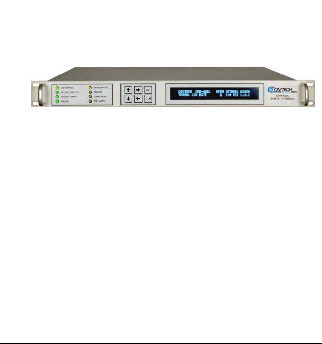
Chapter 1. INTRODUCTION
1.1Overview
The CDM-600/600L Open Network Satellite Modem is intended for both Intelsat and closed network applications. Apart from the IF frequency band, the two modems are essentially identical: The CDM-600L (Figure 1-1) operates on the L-Band frequency, while the CDM-600 is the 70/140 MHz IF version of the same modem.
Figure 1-1. CDM-600/600L Open Network Satellite Modem (CDM-600L shown)
1.1.1Standard Features
The CDM-600/600L provides a wealth of standard features which go far beyond the basic requirements of the Intelsat specifications:
•Low rate variable data rates – 2.4 kbps to 5.0 Mbps
•Mid-rate variable data rates – 2.4 kbps to 10.0 Mbps
•High-rate variable data rates – 2.4 kbps to 20.0 Mbps
•Selectable 50Ω / 75Ω IF port impedance (CDM-600)
•Asymmetric Loop Timing
•Modulation Types – BPSK, QPSK, and OQPSK
•Embedded Distant-end Monitor and Control (EDMAC) (see Note)
•Automatic Uplink Power Control (AUPC)
•Firmware – Flash Upgrading
•1:1 and 1:10 redundancy switch compatibility
1–1

CDM-600/600L Open Network Satellite Modem |
Revision 3 |
Introduction |
MN/CDM600L.IOM |
EDMAC Note: In EDMAC mode, an additional 5% overhead is combined with the traffic data (1.5% in Turbo BPSK modes, Turbo Rate 1/2 QPSK/OQPSK, and all data rates greater than 2 Mbps), which permits Monitor & Control (M&C) information to be added transparently to the user, allowing access to the distant-end modem. This mode does not require any additional cabling at either the local or distant-end modems; access to EDMAC is via the standard M&C control port.
Full M&C is possible and, importantly, the on/off status of the carrier at the distant-end carrier can be controlled. In addition, as of Firmware Ver. 1.2.0 (CDM-600L) or 1.5.0 (CDM-600) and higher, the proprietary D&I++ framing mode is available. This combines Drop & Insert (D&I) operation with a similar EDMAC link and a 2.2% overhead.
CDM-600/600L Common Features
•Compliance with IESS-308 / -309/ -310 / -315 specifications, with significant features added in Closed Network modes.
•Variable data rates from 2.4 kbps to 20 Mbps, in BPSK, QPSK, Offset QPSK, 8-PSK, 8-QAM, and 16-QAM modes are offered.
•Viterbi, Sequential, concatenated Reed-Solomon (RS), Trellis Coded Modulation (TCM), Turbo Product Coding (TPC), and Low Density Parity Check Coding (LDPC) are provided as Forward Error Correction (FEC) options.
•A full range of interface types is built-in and available on demand – no plug-in cards are required. This includes all G.703 types and D&I (both Open and Closed Network) operation.
•The CDM-600/600L front panel features a Video Fluorescent Display (VFD) and keypad for local configuration and control; additionally, the unit may be remote-controlled.
CDM-600L Features
•IF frequency range covers 950 to 1950 MHz, and supports external Block Upconverters (BUCs) and Low-Noise Block Downconverters (LNBs).
•A programmable 13, 18, or 24V LNB power supply at the Rx IF connector center conductor, and optionally includes a 24 or 48V BUC power supply at the Tx IF connector center conductor.
•A low phase noise 10 MHz reference output is available at both the Tx and Rx IF connectors for use by the BUC or LNB.
•The CDM-600L is compact – 1RU high and 18 inches deep, and consumes 57 watts (typical), excluding BUC and LNB power supply loads.
CDM-600 Features
•IF frequency range simultaneously covers 52-88 MHz and 104-176 MHz, and supports external Comtech EF Data RF Transceivers (CSAT-5060, KST-2000A/B).
Note: Units manufactured after February 2005 cover 50-90 MHz and 100-180 MHz. The opening screen for these enhanced operation units displays CDM-600(E)– meaning Extended IF range.
•The CDM-600 is compact – 1RU high and 13.1 inches deep, and consumes only 25 Watts (typical).
Refer to Sect. 1.3 for in-depth product information and Sect. 1.5 for the CDM-600/600L Summary of Specifications.
1–2
 Loading...