


 Loading...
KPA
Ku-Band Indoor Solid-State Power Amplifier Series
Installation and Operation Manual
IMPORTANT NOTE: The information contained in this document supersedes all previously published information regarding this product. Product specifications are subject to change without prior notice.
Part Number MN/KPA.IOM Revision 1
Errata A
Comtech EF Data Documentation Update
Subject: |
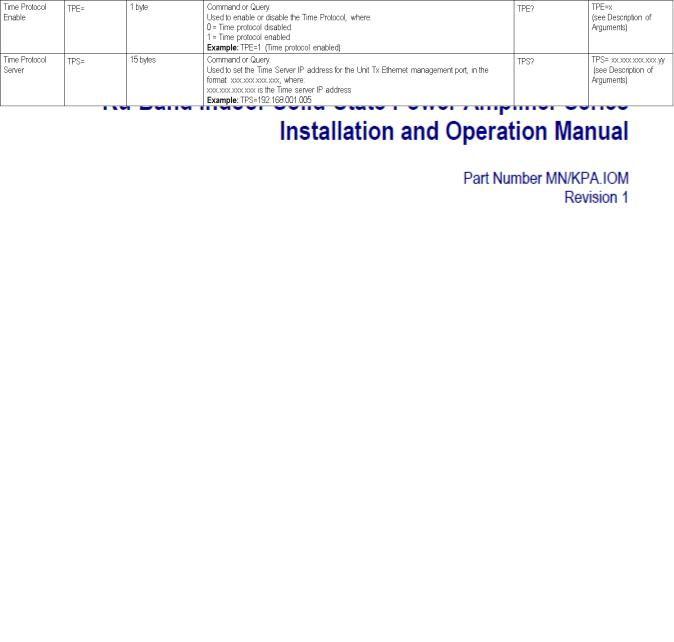
Add TPE and TPS Commands/Queries to Appendix C. REMOTE CONTROL |
|
Sect. C.6.1 Remote Commands and Queries (FW Version 2.X.X and Higher) |
Original Manual Part |
|
Number/Rev: |
MN/KPA.IOM Rev 1 |
Errata Number/ |
|
PLM Document ID: |
ER KPA EA1 |
PLM CO Number: |
C 0027379 |
Comments: |
The updated information will be incorporated into the next formal revision |
|
of the manual: |
|
Add TPE and TPS Commands/Queries to Append C. REMOTE CONTROL |
|
Sect. C.6.1 Remote Commands and Queries (FW Version 2.X.X and |
|
Higher), page C 16: |
ER-KPA-EA1 |
THIS DOCUMENT IS NOT SUBJECT TO REVISION/UPDATE! PLM CO C-0027379 |
Page 1 of 2 |
Errata A for MN/KPA.IOM Rev 1 |
Add TPE and TPS Commands/Queries to Appendix C |
This page is intentionally blank.
ER-KPA-EA1 |
THIS DOCUMENT IS NOT SUBJECT TO REVISION/UPDATE! PLM CO C-0027379 |
Page 2 of 2 |

KPA
Ku-Band Indoor Solid-State Power Amplifier Series
Installation and Operation Manual
Part Number MN/KPA.IOM
Revision 1
October 29, 2010
Copyright © Comtech EF Data, 2010. All rights reserved. Printed in the USA.
Comtech EF Data, 2114 West 7th Street, Tempe, Arizona 85281 USA, 480.333.2200, FAX: 480.333.2161
This page is intentionally blank.

|
|
|
Table of Contents |
TABLE OF CONTENTS .............................................................................................................. |
III |
||
TABLES |
..................................................................................................................................... |
VII |
|
FIGURES ................................................................................................................................... |
VII |
||
PREFACE................................................................................................................................... |
IX |
||
About this Manual ..................................................................................................................................... |
ix |
||
Disclaimer................................................................................................................................................ |
ix |
||
Reporting Comments or Suggestions Concerning this Manual............................................................... |
ix |
||
Military Standards..................................................................................................................................... |
ix |
||
Conventions ......................................................................................................................and References |
x |
||
Metric ....................................................................................................................................Conversion |
x |
||
Recommended .....................................................................................................Standard Designations |
x |
||
Trademarks ............................................................................................................................................... |
x |
||
Cautions ..............................................................................................................................and Warnings |
x |
||
Electrical .............................................................................................................Safety and Compliance |
xi |
||
Electromagnetic ...............................................................................Compatibility (EMC) Compliance |
xi |
||
European .................................................................................................Low Voltage Directive (LVD) |
xi |
||
Warranty ........................................................................................................................................Policy |
xii |
||
Limitations .........................................................................................................................of Warranty |
xii |
||
Exclusive ...............................................................................................................................Remedies |
xiii |
||
Customer ....................................................................................................................................Support |
xiv |
||
Online ......................................................................................................................Customer Support |
xiv |
||
CHAPTER ...........................................................................................1. INTRODUCTION |
1–1 |
||
1.1 |
Overview ..................................................................................................................................... |
1–1 |
|
1.2 |
Functional ..............................................................................................................Description |
1–2 |
|
1.3 |
KPA .....................................................................................................................Specifications |
1–5 |
|
1.3.1 |
...................................................................................................... |
KPA - 020IN Specifications |
1–5 |
1.3.2 |
.......................................................................................................... |
KPA - 040 Specifications |
1–6 |
1.3.3 ................................................................................................ |
KPA - 080 Specifications |
1–7 |
|
iii

KPA Ku-Band Indoor Solid-State Power Amplifier |
Revision 1 |
|||
Table of Contents |
|
MN/KPA.IOM |
||
1.3.4 |
KPA-100 Specifications ................................................................................................ |
1–8 |
||
1.3.5 |
Dimensional Envelopes................................................................................................ |
1–9 |
||
CHAPTER 2. |
INSTALLATION ............................................................................................ |
2–1 |
||
2.1 |
Unpacking and Inspection......................................................................................................... |
2–1 |
||
2.2 |
Rack Mounting the KPA........................................................................................................... |
2–2 |
||
2.2.1 |
Installation of the Optional Rack Slides................................................................... |
2–2 |
||
CHAPTER 3. CONNECTORS AND PINOUTS ................................................................... |
3–1 |
|||
3.1 |
Connector Overview .................................................................................................................. |
3–1 |
||
3.2 |
RF Connections .......................................................................................................................... |
3–3 |
||
3.2.1 J1 RF IN / Tx IN Connectors................................................................................................... |
3–3 |
|||
3.2.2 J2 RF OUT Connector............................................................................................................. |
3–3 |
|||
3.3 |
Utility Connections .................................................................................................................... |
3–4 |
||
3.3.1 Sample Port Connectors (Front Panel) .................................................................................... |
3–4 |
|||
3.3.2 J4 REDUNDANT LOOP Connector....................................................................................... |
3–4 |
|||
3.3.3 J5 DISCRETE CONTROL Connector .................................................................................... |
3–5 |
|||
3.3.4 J8 10/100 ETHERNET Connector .......................................................................................... |
3–6 |
|||
3.3.5 J9A EXT REF IN / J9B EXT REF OUT Connectors.............................................................. |
3–6 |
|||
3.3.6 J7 RF SWITCH Connector...................................................................................................... |
3–7 |
|||
3.3.7 J6 COM 1 Connector............................................................................................................... |
3–7 |
|||
3.4 |
Power / Ground Connections.................................................................................................... |
3–8 |
||
3.4.1 Alternating Current Prime Power Switch and Connector........................................................ |
3–8 |
|||
3.4.2 |
|
Chassis Ground Connector ...................................................................................................... |
3–8 |
|
CHAPTER 4. |
FLASH UPGRADING .................................................................................... |
4–1 |
||
4.1 |
Flash Upgrading via Internet.................................................................................................... |
4–1 |
||
4.2 |
Ethernet FTP Upload Procedure.............................................................................................. |
4–2 |
||
CHAPTER 5. FRONT PANEL OPERATION....................................................................... |
5–1 |
|||
5.1 |
Introduction................................................................................................................................ |
5–1 |
||
5.1.1 |
|
Startup Checklist ..................................................................................................................... |
5–2 |
|
5.1.2 |
|
LED Indicators ........................................................................................................................ |
5–2 |
|
5.1.3 |
|
Keypad |
..................................................................................................................................... |
5–3 |
5.1.4 |
|
Front Panel .................................................................................................................Display |
5–4 |
|
5.2 |
Opening Screen .......................................................................................................................... |
5–4 |
||
5.3 |
SELECT: .............................................................................................................(Main) Menu |
5–5 |
||
5.3.1 |
|
SELECT: ...........................................................................................Config (Configuration) |
5–6 |
|
iv

KPA Ku-Band Indoor Solid-State Power Amplifier |
Revision 1 |
||
Table of Contents |
|
MN/KPA.IOM |
|
5.3.1.1 CONFIG: Remote (Remote Control).............................................................................. |
5–6 |
||
5.3.1.2 |
CONFIG: Amp ............................................................................................................. |
5–10 |
|
5.3.1.3 CONFIG: FltRec (Fault Recovery) Menu Branches..................................................... |
5–11 |
||
5.3.1.4 CONFIG: Redundancy Menu Branches ....................................................................... |
5–11 |
||
5.3.1.5 CONFIG: ExtRef (External Reference)........................................................................ |
5–13 |
||
5.3.2 |
SELECT: Monitor ................................................................................................................. |
5–13 |
|
5.3.2.1 |
MONITOR: Faults........................................................................................................ |
5–14 |
|
5.3.2.2 |
MONITOR: Stored ....................................................................................................... |
5–14 |
|
5.3.2.3 |
MONITOR: Power ....................................................................................................... |
5–15 |
|
5.3.2.4 |
MONITOR: Vltgs ......................................................................................................... |
5–15 |
|
5.3.2.5 MONITOR: PS (Power Supply) ................................................................................... |
5–15 |
||
5.3.2.6 |
MONITOR: Temp ........................................................................................................ |
5–15 |
|
5.3.2.7 |
MONITOR: FETs ......................................................................................................... |
5–15 |
|
5.3.3 |
SELECT: Utility.................................................................................................................... |
5–15 |
|
5.3.3.1 |
UTILITY: Date/Time ................................................................................................... |
5–16 |
|
5.3.3.2 UTILITY: CID (Circuit ID).......................................................................................... |
5–16 |
||
5.3.3.3 |
UTILITY: PowerMon................................................................................................... |
5–16 |
|
5.3.3.4 |
UTILITY: Firmware ..................................................................................................... |
5–17 |
|
5.3.3.5 |
UTILITY: RefOsc......................................................................................................... |
5–17 |
|
5.3.4 |
SELECT: Front Panel............................................................................................................ |
5–18 |
|
5.3.4.1 |
Front Panel: Brightness................................................................................................. |
5–18 |
|
5.3.4.2 Front Panel: Lamp Test................................................................................................. |
5–18 |
||
CHAPTER 6. KPA ETHERNET MANAGEMENT ............................................................... |
6–1 |
||
6.1 |
Overview ..................................................................................................................................... |
6–1 |
|
6.2 |
Ethernet Management Interface Protocols.............................................................................. |
6–1 |
|
6.3 |
SNMP Interface.......................................................................................................................... |
6–1 |
|
6.3.1 Management Information Base (MIB) Files............................................................................ |
6–2 |
||
6.3.2 |
SNMP Community Strings...................................................................................................... |
6–2 |
|
6.4 |
Telnet Interface .......................................................................................................................... |
6–3 |
|
6.5 |
Web Server (HTTP) Interface .................................................................................................. |
6–4 |
|
6.5.1 Web Server page Introduction................................................................................................. |
6–4 |
||
6.5.2 Web Server Interface Access................................................................................................... |
6–4 |
||
6.5.3 Web Server Menu Tree............................................................................................................ |
6–5 |
||
6.5.4 Web Server page Descriptions ................................................................................................ |
6–5 |
||
6.5.4.1 |
Home pages..................................................................................................................... |
6–6 |
|
|
6.5.4.1.1 Home (Splash) page.................................................................................................. |
6–6 |
|
|
6.5.4.1.2 Home | Support page................................................................................................. |
6–7 |
|
6.5.4.2 |
Admin pages ................................................................................................................... |
6–8 |
|
|
6.5.4.2.1 Admin | Access page................................................................................................. |
6–8 |
|
|
6.5.4.2.2 Admin | SNMP page............................................................................................... |
6–10 |
|
6.5.4.3 |
Config (Configuration) pages ....................................................................................... |
6–11 |
|
|
6.5.4.3.1 Config | Amplifier page .......................................................................................... |
6–11 |
|
|
6.5.4.3.2 Config | Utility page ............................................................................................... |
6–13 |
|
|
6.5.4.3.3 Config | Redundancy page...................................................................................... |
6–14 |
|
v

KPA Ku-Band Indoor Solid-State Power Amplifier |
Revision 1 |
|||
Table of Contents |
MN/KPA.IOM |
|||
|
6.5.4.4 |
Status pages................................................................................................................... |
6–16 |
|
|
|
6.5.4.4.1 Status | Events page ................................................................................................ |
6–16 |
|
|
|
6.5.4.4.2 Status | Status page ................................................................................................. |
6–17 |
|
|
|
6.5.4.4.3 Status | FETs page .................................................................................................. |
6–18 |
|
APPENDIX A. MAINTENANCE AND TROUBLESHOOTING ........................................... |
A–1 |
|||
A.1 |
|
Introduction............................................................................................................................... |
A–1 |
|
A.2 |
|
Maintenance Testing................................................................................................................. |
A–2 |
|
A.2.1 |
Test Point Samples............................................................................................................. |
A–2 |
||
A.3 |
|
Troubleshooting ........................................................................................................................ |
A–2 |
|
A.3.1 |
Troubleshooting Guide....................................................................................................... |
A–3 |
||
APPENDIX B. KPA REDUNDANT OPERATIONS ............................................................ |
B–1 |
|||
B.1 |
|
Introduction............................................................................................................................... |
B–1 |
|
B.2 |
|
Redundancy Operation ............................................................................................................ |
B–2 |
|
B.3 |
|
Redundancy Kit Installation.................................................................................................... |
B–2 |
|
B.3.1 |
|
Redundancy Kit Control Cabling....................................................................................... |
B–4 |
|
B.4 Gain Equalization of Redundant Units................................................................................... |
B–8 |
|||
B.4.1 |
|
Case Examples ................................................................................................................... |
B–9 |
|
APPENDIX C. REMOTE CONTROL .................................................................................. |
C–1 |
|||
C.1 |
|
Overview .................................................................................................................................... |
C–1 |
|
C.2 |
|
EIA-485...................................................................................................................................... |
C–1 |
|
C.3 |
|
EIA-232...................................................................................................................................... |
C–2 |
|
C.4 |
|
Basic Protocol............................................................................................................................ |
C–2 |
|
C.5 |
|
Packet Structure ....................................................................................................................... |
C–3 |
|
C.5.1 |
|
Start of Packet .................................................................................................................... |
C–3 |
|
C.5.2 |
|
Target Address ................................................................................................................... |
C–4 |
|
C.5.3 |
|
Address Delimiter .............................................................................................................. |
C–4 |
|
C.5.4 |
|
Instruction Code ................................................................................................................. |
C–4 |
|
C.5.5 |
|
Instruction Code Qualifier.................................................................................................. |
C–4 |
|
|
C.5.5.1 Backward Compatibility Code Qualifier ....................................................................... |
C–5 |
||
C.5.6 |
|
Optional Message Arguments ............................................................................................ |
C–5 |
|
C.5.7 |
|
End of Packet ..................................................................................................................... |
C–6 |
|
C.6 |
Remote Control Using FW Version 2.X.X and Higher (CURRENT) .................................. |
C–7 |
||
C.6.1 |
|
Remote Commands and Queries (FW Version 2.X.X and Higher) ................................... |
C–8 |
|
vi
KPA Ku-Band Indoor Solid-State Power Amplifier |
Revision 1 |
||
Table of Contents |
MN/KPA.IOM |
||
C.7 |
Remote Control Using Firmware Version 1.X.X (OLD)..................................................... |
|
C–17 |
C.7.1 |
Old Utility Commands ..................................................................................................... |
|
C–18 |
C.7.2 |
Old Configuration Commands ......................................................................................... |
|
C–20 |
C.7.3 |
Old Operating Mode Commands ..................................................................................... |
|
C–21 |
C.7.4 |
Old Status Commands...................................................................................................... |
|
C–22 |
C.7.5 |
Old Stored Alarms............................................................................................................ |
|
C–28 |
C.7.6 |
Error Processing ............................................................................................................... |
|
C–29 |
C.7.7 |
Configuration Errors ........................................................................................................ |
|
C–29 |
C.7.8 |
Time-Outs ........................................................................................................................ |
|
C–29 |
|
|
Tables |
|
Table 3-1. KPA Interface Connectors Summary ...................................................................................... |
|
3–2 |
|
Table 3-2. J4 Redundancy Loop Connector Pinout ................................................................................. |
|
3–4 |
|
Table 3-3. J5 DISCRETE CONTROL Connector Pinout (Standalone or 1:1 Redundant Systems) |
....... 3–5 |
||
Table 3-4. J5 DISCRETE CONTROL Connector Pinout (1:2 Redundant Systems) .............................. |
|
3–6 |
|
Table 3-5. J7 RF SWITCH Connector Pinout ......................................................................................... |
|
3–7 |
|
Table 3-6. J6 COM 1 Connector Pinout (EIA-232/EIA-485 Interface)................................................... |
|
3–7 |
|
Table B-1. KPA Redundancy Kits – Parts List........................................................................................ |
|
B–6 |
|
|
|
Figures |
|
Figure 1-1. Comtech EF Data KPA Family of Ku-Band Solid-State Amplifiers .......................................... |
|
1–1 |
|
Figure 1-2. KPA-020IN/-040 Block Diagram .......................................................................................... |
|
1–3 |
|
Figure 1-3. KPA-080/-100 Block Diagram............................................................................................... |
|
1–4 |
|
Figure 1-4. KPA-020IN Dimensional Envelope (Shown with Optional Slide Railings Installed)........... |
1–9 |
||
Figure 1-5. KPA-040/-080/-100 Dimensional Envelope (Shown with Optional Slide Railings Installed) 1–10
Figure 2-1. Installation of Optional Heavy-Duty Rack Slides (CEFD P/N FP/SL00004) |
........................ 2–3 |
Figure 3-1. KPA Rear Panel Views .......................................................................................................... |
3–1 |
Figure 4-1. Flash Upgrade via Internet ..................................................................................................... |
4–1 |
Figure 5-1. KPA-XXX Front Panel View................................................................................................. |
5–1 |
Figure 5-2. KPA Front Panel Keypad....................................................................................................... |
5–3 |
Figure 5-3. KPA Front Panel Keypad....................................................................................................... |
5–4 |
Figure 5-4. KPA Principle Menu Tree...................................................................................................... |
5–5 |
Figure 6-1. KPA Home (Splash) page ...................................................................................................... |
6–6 |
Figure 6-2. KPA Home | Support page ..................................................................................................... |
6–7 |
Figure 6-3. Admin | Access page .............................................................................................................. |
6–8 |
Figure 6-4. Admin | SNMP page ............................................................................................................ |
6–10 |
Figure 6-5. Config | Amplifier page........................................................................................................ |
6–11 |
Figure 6-6. Config | Utility page............................................................................................................. |
6–13 |
Figure 6-7. Config | Redundancy page ................................................................................................... |
6–14 |
Figure 6-8. Status | Events page.............................................................................................................. |
6–16 |
Figure 6-9. Status | Status page............................................................................................................... |
6–17 |
Figure 6-10. Status | FETs page .............................................................................................................. |
6–18 |
Figure B-1. 1:1 Redundancy Block Diagram........................................................................................... |
B–2 |
Figure B-2. 1:1 Redundancy Installation – Complete.............................................................................. |
B–3 |
Figure B-3. KPA Redundancy System – Control Cabling Schematics ................................................... |
B–4 |
Figure B-4. 1:1 Redundancy Kit Assembly ............................................................................................. |
B–7 |
vii

KPA Ku-Band Indoor Solid-State Power Amplifier |
Revision 1 |
Table of Contents |
MN/KPA.IOM |
This page is deliberately blank.
viii

PREFACE
About this Manual
This manual provides installation and operation information for the Comtech EF Data family of Ku-Band Indoor Solid-State Power Amplifiers (ISSPAs) – the KPA-020IN, KPA-040, KPA-080, and KPA-100. This is a technical document intended for earth station engineers, technicians, and operators responsible for the operation and maintenance of the KPAs.
Revision 1 of this manual represents a complete rewrite in which all content has been updated in its entirety and re-ordered to conform to current Comtech EF Data Technical Publications standards and practices.
Disclaimer
Comtech EF Data has reviewed this manual thoroughly in order that it will be an easy-to-use guide to your equipment. All statements, technical information, and recommendations in this manual and in any guides or related documents are believed reliable, but the accuracy and completeness thereof are not guaranteed or warranted, and they are not intended to be, nor should they be understood to be, representations or warranties concerning the products described.
Further, Comtech EF Data reserves the right to make changes in the specifications of the products described in this manual at any time without notice and without obligation to notify any person of such changes.
If you have any questions regarding your equipment or the information in this manual, please contact Comtech EF Data’s Customer Support Department during normal business hours.
Reporting Comments or Suggestions Concerning this Manual
Comments and suggestions regarding the content and design of this manual are appreciated. To submit comments, please contact the Comtech EF Data Technical Publications department:
TechnicalPublications@comtechefdata.com
Military Standards
References to “MIL-STD-188” apply to the 114A series (i.e., MIL-STD-188-114A), which provides electrical and functional characteristics of the unbalanced and balanced voltage digital interface circuits applicable to both long haul and tactical communications. Specifically, these
ix
KPA Ku-Band Indoor Solid-State Power Amplifier |
Revision 1 |
Preface |
MN/KPA.IOM |
references apply to the MIL-STD-188-114A electrical characteristics for a balanced voltage digital interface circuit, Type 1 generator, for the full range of data rates. For more information, refer to the Department of Defense (DOD) MIL-STD-188-114A, “Electrical Characteristics of Digital Interface Circuits.”
Conventions and References
Metric Conversion
Metric conversion information is located on the inside back cover of this manual. This information is provided to assist the operator in cross-referencing non-Metric to Metric conversions.
Recommended Standard Designations
The Recommended Standard (RS) designation has been superseded by the new designation of the Electronic Industries Association (EIA). References to the old designation may be shown only when depicting actual text displayed on the screen of the unit (RS-232, RS-485, etc.). All other references in the manual will be shown with the EIA designation.
Trademarks
Windows is a trademark of the Microsoft Corporation. Other product names mentioned in this manual may be trademarks or registered trademarks of their respective companies and are hereby acknowledged.
The User should carefully review the information that follows.
IMPORTANT
Cautions and Warnings
IMPORTANT or NOTE indicates a statement that is associated with the task being performed or information critical for proper equipment function.
IMPORTANT
CAUTION indicates a hazardous situation that, if not avoided, may result in minor or moderate injury. CAUTION may also be used to indicate other unsafe practices or risks of property damage.
WARNING indicates a potentially hazardous situation that, if not avoided, could result in death or serious injury.
x

KPA Ku-Band Indoor Solid-State Power Amplifier |
Revision 1 |
Preface |
MN/KPA.IOM |
Electrical Safety and Compliance
WARNING
CAUTION
This product contains a Lithium Battery. DANGER OF EXPLOSION EXISTS if the battery is incorrectly replaced. Replace only with the same or equivalent type recommended by the manufacturer. Dispose of used batteries in accordance with local and national regulations
This equipment has been designed to minimize exposure of personnel to hazards. The operators and technicians must:
•Know how to work around, with, and on high voltage and high RF power level equipment.
•Exercise every precaution to ensure personnel safety.
•Exercise extreme care when working near high voltages/high RF power level equipment.
•Be familiar with the warnings presented in this manual.
•Disconnect the power supply cord before servicing the ISSPA.
Electromagnetic Compatibility (EMC) Compliance
Properly shielded cables for DATA I/O are required in order to meet the European Electromagnetic Compatibility (EMC) Directive (EN55022, EN50082-1). More specifically,
IMPORTANT these cables must be shielded from end-to-end, ensuring a continuous ground shield.
In accordance with European Directive 2004/108/EEC, the KPA family of products has been shown, by independent testing, to comply with the following standards:
Emissions: EN 55022 Class B – Limits and Methods of Measurement of Radio Interference Characteristics of Information Technology Equipment.
(Also tested to FCC Part 15 Class B.)
Immunity: EN 55024 – Information Technology Equipment: Immunity Characteristics, Limits, and Methods of Measurement.
European Low Voltage Directive (LVD)
The following information is applicable for the European Low Voltage Directive (2006/95/EC):
Symbol |
|
Description |
||
|
|
|
|
|
<HAR> |
|
Type of power cord required for use in the European Community. |
||
|
|
|
|
|
|
! |
|
|
CAUTION: Double-pole/Neutral Fusing |
|
|
|
ACHTUNG: Zweipolige bzw. Neutralleiter-Sicherung |
|
|
|
|
||
|
|
|
|
|
xi

KPA Ku-Band Indoor Solid-State Power Amplifier |
|
|
|
|
|
|
|
Revision 1 |
||||||
Preface |
|
|
|
|
|
|
|
|
|
MN/KPA.IOM |
||||
|
|
|
|
|
|
|
|
|
|
|
|
|
|
|
|
|
|
|
|
International Symbols |
|
|
|
||||||
|
|
|
|
|
|
|
|
|
|
|
|
|
|
|
|
Symbol |
|
Definition |
Symbol |
|
Definition |
|
|||||||
|
|
|
|
|
|
|
|
|
|
|
|
|
|
|
|
|
|
|
|
Alternating Current |
|
|
|
|
|
|
|
Protective Earth |
|
|
|
|
|
|
|
|
|
|
|
|
|
|
||
|
|
|
|
|
|
|
|
|
|
|
|
|
|
|
|
|
|
|
|
|
|
|
|
|
|
|
|
|
|
|
|
|
|
|
Fuse |
|
|
|
|
|
|
|
Chassis Ground |
|
|
|
|
|
|
|
|
|
|
|
|
|
|
||
|
|
|
|
|
|
|
|
|
|
|
|
|||
|
|
|
|
|
|
|
|
|
|
|
|
|
|
|
For additional symbols, refer to Cautions and Warnings listed earlier in this Preface.
IMPORTANT
Warranty Policy
Comtech EF Data products are warranted against defects in material and workmanship for a specific period from the date of shipment, and this period varies by product. In most cases, the warranty period is two years. During the warranty period, Comtech EF Data will, at its option, repair or replace products that prove to be defective. Repairs are warranted for the remainder of the original warranty or a 90 day extended warranty, whichever is longer. Contact Comtech EF Data for the warranty period specific to the product purchased.
For equipment under warranty, the owner is responsible for freight to Comtech EF Data and all related customs, taxes, tariffs, insurance, etc. Comtech EF Data is responsible for the freight charges only for return of the equipment from the factory to the owner. Comtech EF Data will return the equipment by the same method (i.e., Air, Express, Surface) as the equipment was sent to Comtech EF Data.
All equipment returned for warranty repair must have a valid RMA number issued prior to return and be marked clearly on the return packaging. Comtech EF Data strongly recommends all equipment be returned in its original packaging.
Comtech EF Data Corporation’s obligations under this warranty are limited to repair or replacement of failed parts, and the return shipment to the buyer of the repaired or replaced parts.
Limitations of Warranty
The warranty does not apply to any part of a product that has been installed, altered, repaired, or misused in any way that, in the opinion of Comtech EF Data Corporation, would affect the reliability or detracts from the performance of any part of the product, or is damaged as the result of use in a way or with equipment that had not been previously approved by Comtech EF Data Corporation.
The warranty does not apply to any product or parts thereof where the serial number or the serial number of any of its parts has been altered, defaced, or removed.
The warranty does not cover damage or loss incurred in transportation of the product.
xii

KPA Ku-Band Indoor Solid-State Power Amplifier |
Revision 1 |
Preface |
MN/KPA.IOM |
The warranty does not cover replacement or repair necessitated by loss or damage from any cause beyond the control of Comtech EF Data Corporation, such as lightning or other natural and weather related events or wartime environments.
The warranty does not cover any labor involved in the removal and or reinstallation of warranted equipment or parts on site, or any labor required to diagnose the necessity for repair or replacement.
The warranty excludes any responsibility by Comtech EF Data Corporation for incidental or consequential damages arising from the use of the equipment or products, or for any inability to use them either separate from or in combination with any other equipment or products.
A fixed charge established for each product will be imposed for all equipment returned for warranty repair where Comtech EF Data Corporation cannot identify the cause of the reported failure.
Exclusive Remedies
Comtech EF Data Corporation’s warranty, as stated is in lieu of all other warranties, expressed, implied, or statutory, including those of merchantability and fitness for a particular purpose. The buyer shall pass on to any purchaser, lessee, or other user of Comtech EF Data Corporation’s products, the aforementioned warranty, and shall indemnify and hold harmless Comtech EF Data Corporation from any claims or liability of such purchaser, lessee, or user based upon allegations that the buyer, its agents, or employees have made additional warranties or representations as to product preference or use.
The remedies provided herein are the buyer’s sole and exclusive remedies. Comtech EF Data shall not be liable for any direct, indirect, special, incidental, or consequential damages, whether based on contract, tort, or any other legal theory.
xiii

KPA Ku-Band Indoor Solid-State Power Amplifier |
Revision 1 |
Preface |
MN/KPA.IOM |
Customer Support
Refer to p. xii in this Preface for information regarding this product’s Warranty Policy.
Contact the Comtech EF Data Customer Support Department for:
•Product support or training
•Reporting comments or suggestions concerning manuals
•Information on upgrading or returning a product
A Customer Support representative may be reached during normal business hours at:
Comtech EF Data
Attention: Customer Support Department 2114 West 7th Street
Tempe, Arizona 85281 USA
480.333.2200 (Main Comtech EF Data number) 480.333.4357 (Customer Support Desk) 480.333.2161 FAX
To return a Comtech EF Data product (in-warranty and out-of-warranty) for repair or replacement:
•Contact the Comtech EF Data Customer Support Department during normal business hours. Be prepared to supply the Customer Support representative with the model number, serial number, and a description of the problem.
•Request a Return Material Authorization (RMA) number from the Comtech EF Data Customer Support representative.
•Pack the product in its original shipping carton/packaging to ensure that the product is not damaged during shipping.
•Ship the product back to Comtech EF Data. (Shipping charges should be prepaid.)
Online Customer Support
An RMA number can be requested electronically by accessing Comtech EF Data’s online
Support page (www.comtechefdata.com/support.asp). From this page:
•Click the Service hyperlink, then read the Return Material Authorization section for detailed instructions on Comtech EF Data’s return procedures.
•Click [Send RMA Request] on the Support page or the RMA Request hyperlink provided in the Service | Return Material Authorization section; fill out the Billing Information,
Return Information, and Unit to be Returned sections completely, then click [Send email]
– or –
•Send an e-mail providing this same detailed information to the Customer Support Department at service@comtechefdata.com.
xiv
Chapter 1. INTRODUCTION
1.1Overview
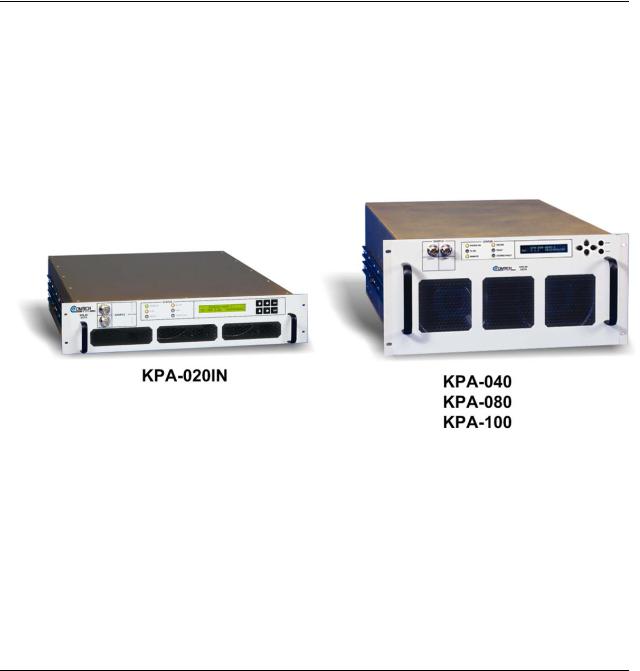
The Comtech EF Data Ku-Band Solid-State Power Amplifier (KPA) family of products, shown in Figure 1-1, is a line of Indoor Solid-State Power Amplifiers (ISSPAs) designed for use in communication systems or satellite uplink data systems. The KPA operates over the RF input frequency range of 14.0 to 14.5 GHz and provides a cost effective and more reliable replacement for Traveling Wave Tube (TWT) amplifiers in Ku-Band terminals.
Due to its small form factor, it is also ideal for the construction of small “flyaway” terminals, medium size (equivalent to Intelsat F) earth stations, hub earth stations for small to medium size private networks, or point-to-point links.
Figure 1-1. Comtech EF Data KPA Family of Ku-Band Solid-State Amplifiers
1–1

Ku-Band Solid-State Power Amplifier |
Revision 1 |
Introduction |
MN/KPA.IOM |
1.2Functional Description
Each KPA ISSPA is constructed with highly reliable Gallium Arsenide Field Effect Transistors (GaAs FETs). With Third-Order Intermodulation products from 4 to 6 dB better than TWT ratings, the Comtech EF Data unit replaces TWTs with saturated power levels of up to twice the KPA’s rated output. These KPAs also provide a Mean Time Between Failure (MTBF) that is 4 to 5 times greater than the typical TWT MTBFs.
The KPA is designed to be rack-mounted in a standard 19-inch (48 cm) rack or cabinet by hardmounting the unit to the rack’s front mounting rails using the front panel mounting holes; optionally, rack slides may be installed onto the chassis that allow servicing of the unit without its removal from the rack. Handles at the front of the unit facilitate easy installation into and removal from the rack.
All user controls, indicators, and displays for local and remote operation – as well as the RF Input and Output sample test ports – are located on the front panel of the unit. User external interface connectors are located on the chassis rear panel.
Two internally mounted exhaust fans provide cooling – cool air is taken in through the front panel and exhausted out the rear panel.
An AC power connector and On/Off switch are located on the chassis rear panel. A six-foot AC power cord is supplied with the unit.
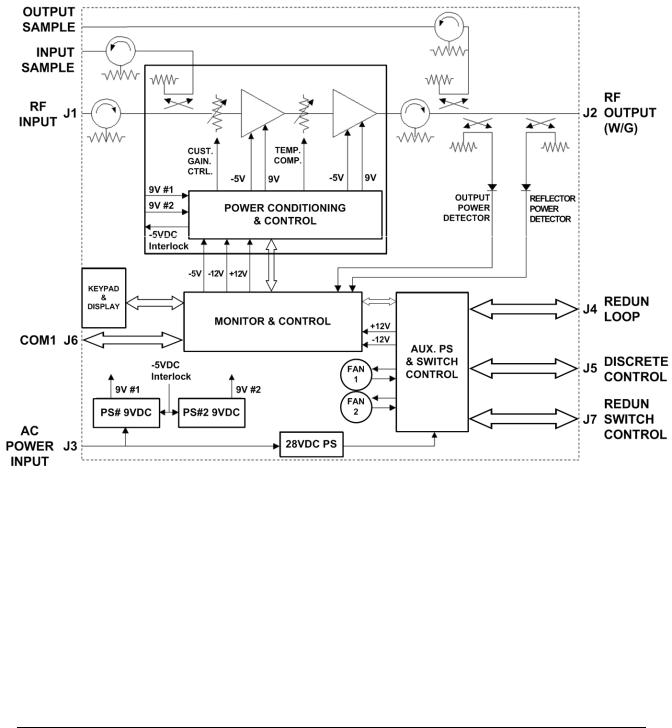
On the pages that follow, Figure 1-2 and Figure 1-3 depict the block diagrams for the available KPAs. Each KPA chassis consists of a power supply, fan assembly, front panel assembly, monitor/control processor (MCP), and a Comtech EF Data SSPA module. The KPA is designed using a Comtech EF Data low loss combining technique and an MCP based temperature versus gain compensation.
The front panel features:
•A Vacuum Fluorescent Display for user-friendly visual status update (Liquid Crystal Diode display for KPA-020IN and older KPA-040/-080/-100 units)
•The six-button cursor array is used to set or change operating parameters
•Six Light-Emitting Diodes (LEDs) provide quick reference to binary status points
•Input and output sample ports at –20 dBc and–40 dBc provide easy test point access
Each unit has the ability to function as a 1:1 or 1:2 redundancy controller in the backup mode. The optional redundancy configuration is implemented by attaching a ganged waveguide/coax transfer switch(es) to input and output connectors of the amplifiers with a combination coaxial cable and waveguide kit. When the backup KPA is commanded into the controller mode, it monitors the online KPAs for faults. A faulted online unit may be disconnected and replaced without affecting the online power amplifier. For detailed information about using the KPA in 1:1 or 1:2 redundancy, see Appendix B. KPA REDUNDANT OPERATIONS.
1–2
Ku-Band Solid-State Power Amplifier |
Revision 1 |
Introduction |
MN/KPA.IOM |
Figure 1-2. KPA-020IN/-040 Block Diagram
1–3
Ku-Band Solid-State Power Amplifier |
Revision 1 |
Introduction |
MN/KPA.IOM |
Figure 1-3. KPA-080/-100 Block Diagram
1–4

Ku-Band Solid-State Power Amplifier |
Revision 1 |
Introduction |
MN/KPA.IOM |
1.3KPA Specifications
1.3.1KPA-020IN Specifications
|
Parameters |
|
|
Specifications |
|
|
Input |
|
Level |
|
-10dBm Typical |
|
|
|
Impedance |
|
50Ω |
|
|
|
Noise Figure |
|
10 dB Typical, 15 dB max @ max gain |
|
|
|
VSWR |
|
1.25: 1 maximum |
|
|
|
Connector |
|
SMA Female |
|
Output |
|
Frequency |
|
14.0 to 14.5 GHz |
|
|
|
Power |
|
42.5 dBm minimum @ 1 dB Compression |
|
|
|
Mute |
|
60 dB |
|
|
|
VSWR |
|
1.25:1 maximum |
|
|
|
Connector |
|
WR75G Waveguide |
|
Gain |
|
Linear |
|
50 dB minimum, 53 dB Typical |
|
|
|
Adjust |
|
20 dB in 0.25 dB steps |
|
|
|
Fill Band |
|
± 0.75 dB |
|
|
|
Per 40 MHz |
|
± -0.25 dB |
|
|
|
0 to +50°C (32 to 122°F) |
± 0.75dB |
|
|
|
|
Intercept |
|
+56.5 dBm minimum, 59.0 Typical |
|
Third Order Modulation |
|
|
||
|
|
|
Products |
|
-25 dBc max, -30 dBc typical @ 3 dB total |
|
|
|
|
|
backoff from rated P1dB (two tones, f+MHz) |
|
AM to PM Conversion |
|
Output |
|
2.0 degrees typical |
|
|
|
|
|
3.0 max @ 42.5 dBm |
|
Group Delay (per 40 |
|
Linear |
|
± 0.03 ns/MHz |
|
MHz) |
|
Parabolic |
|
± 0.0025 ns/MHz2 |
|
|
|
|||
|
|
|
Ripple |
|
1.0 ns Peak-to-Peak |
|
|
|
Display |
|
24 x 2 LCD |
|
Front Panel |
|
|
||
|
|
|
Data Entry |
|
Cursor Control Keypad (6 keys) |
|
|
|
Output Sample |
|
Type N female, 50Ω, –40 dBc |
|
|
|
Input Sample |
|
Type N female, 50Ω, –20 dBc |
|
Remote Control |
|
COM Port |
|
EIA-232 or EIA-485 |
|
|
|
Protocol |
|
ASCII |
|
Alarms |
Summary Fault |
|
Form C |
|
|
LEDs |
|
Power On |
|
Green |
|
|
|
Fault |
|
Red |
|
|
|
Stored Fault |
|
Red |
|
|
|
TX On |
|
Yellow |
|
|
|
Online |
|
Yellow |
|
|
|
Remote |
|
Yellow |
|
|
|
Envelope |
|
3.5H x 19W x 24D inches |
|
Mechanical |
|
|
||
|
|
|
|
|
(8.89H x 48.26W x 60.96D cm) |
|
|
|
Weight |
|
TBD |
|
Environmental |
|
Temperature |
Operating |
0 to 50°C (32 to 122°F) |
|
|
|
|
Storage |
–40 to 70°C (–40 to 158°F) |
|
|
|
Humidity |
Operating |
10 to 95% Noncondensing |
|
|
|
|
Storage |
0 to 100% Noncondensing |
|
|
|
Altitude |
Operating |
15, 000 ft MSL |
|
|
|
|
Storage |
50, 000 ft |
|
|
|
Shock |
|
Normal Commercial Shipping and Handling |
|
Power Requirements |
|
VAC |
|
90 to 135 or 180 to 270 VAC, 47 to 63 Hz |
|
|
|
|
|
400W (Auto Select) |
1–5

Ku-Band Solid-State Power Amplifier |
Revision 1 |
Introduction |
MN/KPA.IOM |
1.3.2KPA-040 Specifications
|
Parameters |
|
|
Specifications |
|
|
Input |
|
Level |
|
10 dBm Typical |
|
|
|
Impedance |
|
50Ω |
|
|
|
Noise Figure |
|
10 dB typical, 15 dB maximum @ max gain |
|
|
|
VSWR |
|
1.25:1 Maximum |
|
|
|
Connector |
|
SMA Female |
|
Output |
|
Frequency |
|
14.0 to 14.5 GHz |
|
|
|
Power |
|
45.5 dBm min @ 1 dB Compression |
|
|
|
Mute |
|
-60 dB |
|
|
|
Impedance |
|
50 Ω |
|
|
|
VSWR |
|
1.25:1 Maximum |
|
|
|
Connector |
|
WR75G Waveguide |
|
Gain |
|
Linear |
|
60.0 dB minimum, 63 dB typical |
|
|
|
Adjust |
|
20 dB in 0.25 dB steps |
|
|
|
Fill Band |
|
± 0.75 dB |
|
|
|
Per 40 MHz |
|
± 0.25 dB |
|
|
|
0 to +50°C (32 to 122°F) |
± 0.50 dB @ center frequency |
|
|
|
|
|
|
± 1.00 dB full band |
|
|
|
Intercept |
|
+53.5 dBm minimum, 56.0 dBm typical |
|
Third Order Modulation |
|
|
||
|
|
|
Products |
|
-30 dBc typical @ –25 dBc maximum |
|
|
|
|
|
3 dB total backoff (2 tones, f = 1 MHz) |
|
|
|
Output |
|
2.0 degrees typical, 3.0 maximum @ rated output |
|
AM to PM Conversion |
|
|||
|
Group Delay (per 40 |
|
Linear |
|
± 0.03 ns/MHz |
|
MHz) |
|
Parabolic |
|
± 0.03 ns/MHz2 |
|
|
|
|||
|
|
|
Ripple |
|
1.0 ns Peak-to-Peak |
|
|
|
Display |
|
24 x 2 LCD |
|
Front Panel |
|
|
||
|
|
|
Data Entry |
|
Cursor Control Keypad (6 keys) |
|
|
|
Output Sample |
|
Type N, 50Ω, –40 dBc |
|
|
|
Input Sample |
|
Type N, 50Ω, –20 dBc |
|
Remote Control |
|
COM Port |
|
EIA-232 or EIA-485 |
|
|
|
Protocol |
|
ASCII |
|
|
|
Summary Fault |
|
Form C |
|
Alarms |
|
|||
|
|
|
Power On |
|
Green |
|
LEDs |
|
|
||
|
|
|
Fault |
|
Red |
|
|
|
Stored Fault |
|
Red |
|
|
|
TX On |
|
Yellow |
|
|
|
Online |
|
Yellow |
|
|
|
Remote |
|
Yellow |
|
Mechanical |
|
Envelope |
|
7H x 19W x 24D inches |
|
|
|
|
|
(18H x 48.26W x 60.96D cm) |
|
|
|
Weight |
|
TBD |
|
Environmental |
|
Temperature |
Operating |
0 to 50°C (32 to 122°F) |
|
|
|
|
Storage |
–40 to 70°C (–40 to 158°F) |
|
|
|
Humidity |
Operating |
10 to 95% Noncondensing |
|
|
|
|
Storage |
0 to 100% Noncondensing |
|
|
|
Altitude |
Operating |
15, 000 ft MSL |
|
|
|
|
Storage |
50, 000 ft |
|
|
|
Shock |
|
Normal Commercial Shipping and Handling |
|
Power Requirements |
|
VAC |
|
90 to 135 VAC, or 180 to 270 VAC, 47 to 63 |
|
|
|
|
|
Hz, 600W (Auto-Select) |
1–6

Ku-Band Solid-State Power Amplifier |
Revision 1 |
Introduction |
MN/KPA.IOM |
1.3.3 KPA-080 Specifications
|
Parameters |
|
|
Specifications |
|
|
Input |
|
Impedance |
|
50Ω |
|
|
|
Noise Figure |
|
10 dB typical, 15 dB maximum @ max gain |
|
|
|
VSWR |
|
1.25:1 Maximum |
|
|
|
Connector |
|
SMA Female |
|
Output |
|
Frequency |
|
14.0 to 14.5 GHz |
|
|
|
Power |
|
48.5 dBm min @ 1 dB Compression |
|
|
|
Mute |
|
60 dB |
|
|
|
Impedance |
|
50 Ω |
|
|
|
VSWR |
|
1.25:1 Maximum |
|
|
|
Connector |
|
WR75G Waveguide |
|
Gain |
|
Linear |
|
61 dB minimum, 64 dB typical |
|
|
|
Adjust |
|
20 dB in 0.25 dB steps |
|
|
|
Fill Band |
|
± 0.75 dB |
|
|
|
Per 40 MHz |
|
± -0.25 dB |
|
|
|
0 to +50°C (32 to 122°F) |
± 0.50 dB @ center frequency |
|
|
|
|
|
|
± 1.00 dB full band |
|
Third Order Modulation |
|
Products |
|
-30 dBc typical @ –25 dBc maximum @ 3 dB |
|
|
|
|
|
total backoff (2 tones, f = 1 MHz) |
|
AM to PM Conversion |
Output |
|
2.0 degrees typical, 3.0 maximum @ rated output |
|
|
Group Delay (per 40 |
|
Linear |
|
± 0.03 ns/MHz |
|
MHz) |
|
Parabolic |
|
± 0.003 ns/MHz2 |
|
|
|
|||
|
|
|
Ripple |
|
1.0 ns Peak-to-Peak |
|
Front Panel |
|
Display |
|
24 x 2 LCD |
|
|
|
Data Entry |
|
Cursor Control Keypad (6 keys) |
|
|
|
Output Sample |
|
Type N female, 50Ω, –40 dBc |
|
|
|
Input Sample |
|
Type N female, 50Ω, –20 dBc |
|
Remote Control |
|
COM Port |
|
EIA-232 or EIA-485 |
|
|
|
Protocol |
|
ASCII |
|
Alarms |
Summary Fault |
|
Form C |
|
|
LEDs |
|
Power On |
|
Green |
|
|
|
Fault |
|
Red |
|
|
|
Stored Fault |
|
Red |
|
|
|
TX On |
|
Yellow |
|
|
|
Online |
|
Yellow |
|
|
|
Remote |
|
Yellow |
|
|
|
Envelope |
|
8.75H x 19W x 24D inches |
|
Mechanical |
|
|
||
|
|
|
|
|
(22.22H x 48.26W x 60.96D cm) |
|
|
|
Weight |
|
75 lbs (34 kg) |
|
Environmental |
|
Temperature |
Operating |
0 to 50°C (32 to 122°F) |
|
|
|
|
Storage |
–40 to 70°C (–40 to 158°F) |
|
|
|
Humidity |
Operating |
10 to 95% Noncondensing |
|
|
|
|
Storage |
0 to 100% Noncondensing |
|
|
|
Altitude |
Operating |
15, 000 ft MSL |
|
|
|
|
Storage |
50, 000 ft |
|
|
|
Shock |
|
Normal Commercial Shipping and Handling |
|
|
|
VAC |
|
180 to 270 VAC, 47 to 63 Hz |
|
Power Requirements |
|
|
||
|
|
|
|
|
1100W nominal |
1–7

Ku-Band Solid-State Power Amplifier |
Revision 1 |
Introduction |
MN/KPA.IOM |
1.3.4 KPA-100 Specifications
|
Parameters |
|
|
Specifications |
|
|
Input |
|
Level |
|
-10 dBm Typical |
|
|
|
Impedance |
|
50Ω |
|
|
|
Noise Figure |
|
10 dB typical, 15 dB maximum @ max gain |
|
|
|
VSWR |
|
1.25:1 Maximum |
|
|
|
Connector |
|
SMA Female |
|
Output |
|
Frequency |
|
14.0 to 14.5 GHz |
|
|
|
Power |
|
49.5 dBm min @ 1 dB Compression |
|
|
|
Mute |
|
-60 dB |
|
|
|
Impedance |
|
50 Ω |
|
|
|
VSWR |
|
1.25:1 Maximum |
|
|
|
Connector |
|
WR75G Waveguide |
|
Gain |
|
Linear |
|
65 dB minimum, 70 dB typical |
|
|
|
Adjust |
|
20 dB in 0.25 dB steps |
|
|
|
Fill Band |
|
± 0.75 dB |
|
|
|
Per 40 MHz |
|
± 0.25 dB |
|
|
|
0 to +50°C (32 to 122°F) |
± 0.50 dB @ center frequency |
|
|
|
|
|
|
± 1.00 dB full band |
|
|
|
Products |
|
-30 dBc typical @ –25 dBc maximum @ 3 dB |
|
Third Order Modulation |
|
|
||
|
|
|
|
|
total backoff (2 tones, f = 1 MHz) |
|
AM to PM Conversion |
Output |
|
2.0 degrees typical, 3.0 maximum @ rated output |
|
|
Group Delay (per 40 |
|
Linear |
|
± 0.03 ns/MHz |
|
MHz) |
|
Parabolic |
|
± 0.003 ns/MHz2 |
|
|
|
|||
|
|
|
Ripple |
|
1.0 ns Peak-to-Peak |
|
Front Panel |
|
Display |
|
24 x 2 LCD |
|
|
|
Data Entry |
|
Cursor Control Keypad (6 keys) |
|
|
|
Output Sample |
|
Type N female, 50Ω, –40 dBc |
|
|
|
Input Sample |
|
Type N female, 50Ω, –20 dBc |
|
Remote Control |
|
COM Port |
|
EIA-232 or EIA-485 |
|
|
|
Protocol |
|
ASCII |
|
Alarms |
Summary Fault |
|
Form C |
|
|
LEDs |
|
Power On |
|
Green |
|
|
|
Fault |
|
Red |
|
|
|
Stored Fault |
|
Red |
|
|
|
TX On |
|
Yellow |
|
|
|
Online |
|
Yellow |
|
|
|
Remote |
|
Yellow |
|
Mechanical |
|
Envelope |
|
8.75H x 19W x 24D inches |
|
|
|
|
|
(22.22H x 48.26W x 60.96D cm) |
|
|
|
Weight |
|
75 lbs (34 kg) |
|
Environmental |
|
Temperature |
Operating |
0 to 50°C (32 to 122°F) |
|
|
|
|
Storage |
–40 to 70°C (–40 to 158°F) |
|
|
|
Humidity |
Operating |
10 to 95% Noncondensing |
|
|
|
|
Storage |
0 to 100% Noncondensing |
|
|
|
Altitude |
Operating |
15, 000 ft MSL |
|
|
|
|
Storage |
50, 000 ft |
|
|
|
Shock |
|
Normal Commercial Shipping and Handling |
|
Power Requirements |
|
VAC |
|
180 to 270 VAC, 47 to 63 Hz |
|
|
|
|
|
1100W nominal |
1–8
Ku-Band Solid-State Power Amplifier |
Revision 1 |
Introduction |
MN/KPA.IOM |
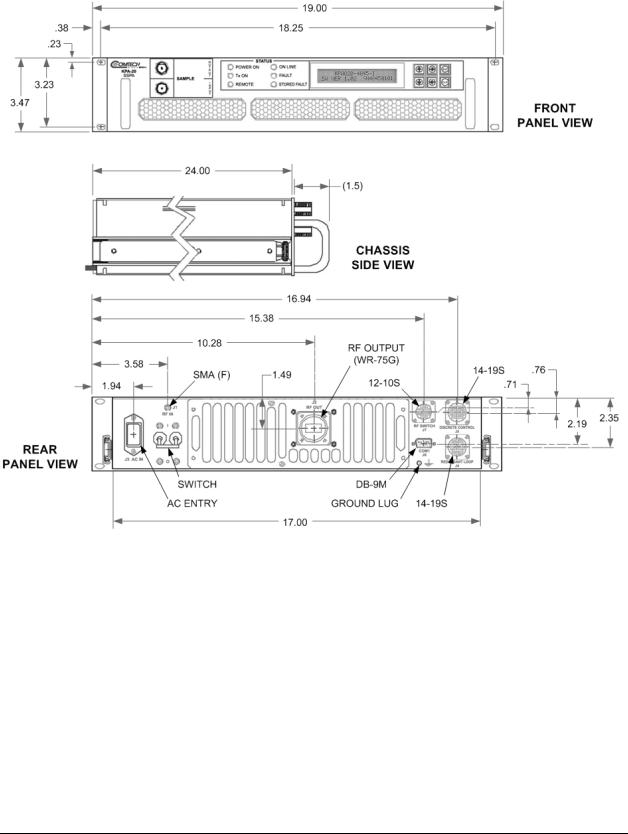
1.3.5 Dimensional Envelopes
Figure 1-4. KPA-020IN Dimensional Envelope (Shown with Optional Slide Railings Installed)
1–9

Ku-Band Solid-State Power Amplifier |
Revision 1 |
Introduction |
MN/KPA.IOM |
Figure 1-5. KPA-040/-080/-100 Dimensional Envelope (Shown with Optional Slide Railings Installed)
1–10
Chapter 2. INSTALLATION
2.1Unpacking and Inspection
The KPA ISSPA and its Installation and Operation Manual are packaged and shipped in a preformed, reusable cardboard carton containing foam spacing for maximum shipping protection.
Do not use any cutting tool that will extend more than 1 inch into the container. This can cause damage to the unit.
CAUTION
Unpack and inspect the unit as follows:
Step Procedure
1Inspect shipping containers for damage.
2If shipping containers are damaged, keep them until the contents of the shipment have been carefully inspected and checked for normal operation.
3Remove the packing list from the outside of the shipping carton.
4Open the carton and remove the contents.
5Check the contents against the packing list to verify completeness of the shipment.
6If physical damage is evident, contact the carrier and Comtech EF Data immediately and submit a damage report.
7Test the unit for proper operation.
8If the unit needs to be returned to Comtech EF Data, use the original shipping container.
Be sure to keep all shipping materials for the carrier's inspection.
2–1

KPA Ku-Band Indoor Solid State Power Amplifier |
Revision 1 |
Installation |
MN/KPA.IOM |
2.2Rack Mounting the KPA
The KPA is designed to be rack-mounted in a standard 19-inch (48 cm) rack or cabinet by hardmounting the unit to the rack’s front mounting rails using the front panel mounting holes/ Handles at the front of the units facilitate easy installation into and removal from the rack. Optionally, rack slides may be installed onto the chassis that allow servicing of the unit without its removal from the rack.
The KPA-020IN chassis is a 3RU unit requiring 4 inches (10 cm) of panel height space. The KPA-040/-080/-100 units are 5RU units requiring 8.75 inches (22 cm) of panel height space.
Two internally mounted exhaust fans provide cooling – cool air is taken in through the front panel and exhausted out the rear panel. Locate the KPA so that the input and output airflow paths are not obstructed or restricted. This will minimize the amplifier operating temperature.
It is important to ensure that there is adequate clearance for ventilation in the rack. In rack systems where there is high heat dissipation, provide forced-air cooling by installing topor bottom-mounted fans or blowers.
2.2.1 Installation of the Optional Rack Slides
The following table identifies the rack slides options that may be purchased for use with the KPA unit (take note that the 5RU units require a heavy duty, dual rail rack slide).
KPA Unit |
|
Rack Slide (CEFD P/N) |
|
Description |
|
|
FP/SL0007 |
22” Rack Slide Set (single rail) |
|
KPA-020IN |
|
FP/SL0008 |
24” Rack Slide Set (single rail) |
|
|
|
|
|
|
|
|
FP/SL0006 |
26” Rack Slide Set (single rail) |
|
KPA-040 |
|
|
|
|
KPA-080 |
|
FP/SL0004 |
|
24” Heavy Duty Rack Slide Set (dual rail) |
KPA-100 |
|
|
|
|
|
|
|
|
|
Install the rack slides as follows:
Step Procedure
Typical for either side of the KPA chassis, install the “chassis section” of the rack slide to
1the KPA chassis side, using the pan head machine screws provided with the rack slide installation kit.
Typical for either side of the rack cabinet: using the mounting hardware provided with the rack slide installation kit, install the “stationary section” of the rack slide,
2either to the interior wall of the cabinet (for single rail rack slides) or, for the heavyduty rack slides, to the front and rear mounting rails of the cabinet as shown in
Figure 2-1.
Install the KPA unit into position by mating the chassis-mounted rails into the cabinetmounted stationary portion of the rack slide. Be sure that the ball retainer for either slide
3has first been positioned forward before installing the chassis section.
The user may leave the unit free in place (to slide on the rails freely) or, alternately, bolt the unit into place via the slotted front panel mounting holes.
2–2
Loading...