


 Loading...
MBT-5000
L-Band Up/Down Converter System
Installation and Operation Manual
IMPORTANT NOTE: The information contained in this document supersedes all previously published information regarding this product. Product specifications are subject to change without prior notice.
Part Number MN-MBT5000 Revision 4

MBT-5000
L-Band Up/Down Converter System
Installation and Operation Manual
Part Number MN-MBT5000
Revision 4
Copyright © 2014 Comtech EF Data. All rights reserved. Printed in the USA. Comtech EF Data, 2114 West 7th Street, Tempe, Arizona 85281 USA, 480.333.2200, FAX: 480.333.2161

BLANK PAGE
ii

|
|
TABLE OF CONTENTS |
|
TABLE OF CONTENTS ............................................................................................................ |
III |
||
TABLES ................................................................................................................................. |
|
VIII |
|
FIGURES................................................................................................................................ |
|
VIII |
|
PREFACE................................................................................................................................. |
|
IX |
|
Conventions and References ............................................................................................................. |
ix |
||
Patents and Trademarks .......................................................................................................................... |
ix |
||
Warnings, Cautions, and Notes................................................................................................................ |
ix |
||
Examples of Multi-Hazard Notices............................................................................................................ |
x |
||
Recommended Standard Designations..................................................................................................... |
x |
||
Safety and Compliance....................................................................................................................... |
x |
||
Electrical Safety and Compliance.............................................................................................................. |
x |
||
Electrical Installation................................................................................................................................ |
xi |
||
Operating Environment ........................................................................................................................... |
xi |
||
European Union Radio Equipment and Telecommunications Terminal Equipment (R&TTE) Directive |
|||
(1999/5/EC) and EN 301 489-1 ................................................................................................................ |
xi |
||
|
European Union Electromagnetic Compatibility (EMC) Directive (2004/108/EC) ......................... |
xi |
|
|
European Union Low Voltage Directive (LVD) (2006/95/EC).............................................................. |
xii |
|
|
European Union RoHS Directive (2002/95/EC)................................................................................... |
xiii |
|
|
European Union Telecommunications Terminal Equipment Directive (91/263/EEC)........................ |
xiii |
|
|
CE Mark ............................................................................................................................................... |
xiii |
|
Product Support.............................................................................................................................. |
xiii |
||
Comtech EF Data Headquarters....................................................................................................... |
xiii |
||
Warranty Policy .............................................................................................................................. |
xiii |
||
Limitations of Warranty .......................................................................................................................... |
xiv |
||
Exclusive Remedies ................................................................................................................................. |
xv |
||
CHAPTER 1. INTRODUCTION............................................................................................ |
1–1 |
||
1.1 |
Overview ............................................................................................................................ |
1–1 |
|
1.2 |
Functional Description ........................................................................................................ |
1–1 |
|
1.3 |
Features ............................................................................................................................. |
1–3 |
|
1.3.1 |
Block Upconverter (BUC-5000x) ........................................................................................... |
1–3 |
|
1.3.2 |
Block Downcoverter (BDC-5000x)......................................................................................... |
1–3 |
|
iii

MBT-5000 L-Band Up/Down Converter System |
MN-MBT5000 |
||
Table of Contents |
Revision 4 |
||
1.4 |
Summary of Specifications .................................................................................................. |
1–4 |
|
1.4.1 |
Physical & Environmental ..................................................................................................... |
1–4 |
|
1.4.2 |
Prime Power.......................................................................................................................... |
1–4 |
|
1.4.3 |
Monitor & Control................................................................................................................. |
1–4 |
|
1.4.4 |
Reference .............................................................................................................................. |
1–4 |
|
1.4.5 |
BUC-5000x Block Upconverters ............................................................................................ |
1–5 |
|
1.4.6 |
BDC-5000x Block Downconverters ....................................................................................... |
1–6 |
|
1.5 |
Dimensional Envelope......................................................................................................... |
1–7 |
|
CHAPTER 2. INSTALLATION............................................................................................. |
2–1 |
||
2.1 |
Unpack and Inspect the Shipment ....................................................................................... |
2–1 |
|
2.2 |
Install the Unit Into a Rack Enclosure................................................................................... |
2–2 |
|
2.2.1 |
Install the Optional Rear-Mounting Support Brackets Kit .................................................... |
2–4 |
|
2.2.2 |
Install the Optional Bearingless Rack Slide Set ..................................................................... |
2–5 |
|
CHAPTER 3. REAR PANEL CONNECTIONS..................................................................... |
3–1 |
||
3.1 |
Cabling Connection Types ................................................................................................... |
3–1 |
|
3.1.1 |
Coaxial Cable Connections .................................................................................................... |
3–1 |
|
|
3.1.1.1 |
Type ‘BNC’......................................................................................................................... |
3–2 |
|
3.1.1.2 |
Type ‘TNC’ ......................................................................................................................... |
3–2 |
|
3.1.1.3 |
Type ‘N’ ............................................................................................................................. |
3–2 |
|
3.1.1.4 |
Type ‘F’.............................................................................................................................. |
3–3 |
|
3.1.1.5 Type ‘SMA’ (Subminiature Version ‘A’)............................................................................. |
3–3 |
|
3.1.2 |
D-Subminiature Cable Connections ...................................................................................... |
3–3 |
|
3.1.3 |
RJ-45, RJ-48 Cable Connections ............................................................................................ |
3–4 |
|
3.2 |
MBT-5000 Cabling Connections ........................................................................................... |
3–5 |
|
3.2.1 |
IF Connector Group............................................................................................................... |
3–6 |
|
|
3.2.1.1 ‘J4 | IF OUT/IN’ (Side B) Connector (Type ‘N’ Female) ..................................................... |
3–6 |
|
|
3.2.1.2 ‘J5 | RF IN/OUT’ (Side B) Connector (Type ‘N’ Female) .................................................... |
3–6 |
|
|
3.2.1.3 ‘J6 | IF OUT/IN’ (Side A) Connector (Type ‘N’ Female) ..................................................... |
3–6 |
|
|
3.2.1.4 ‘J7 | RF IN/OUT’ (Side A) Connector (Type ‘N’ Female) .................................................... |
3–6 |
|
3.2.2 |
Optional Redundancy Groups ............................................................................................... |
3–7 |
|
|
3.2.2.1 Optional ‘RF’ Connectors (Type ‘SMA’ Female) ................................................................ |
3–7 |
|
|
3.2.2.2 Optional ‘IF’ Connectors (Type ‘SMA’ Female) ................................................................. |
3–7 |
|
3.2.3 |
Utility Connector Group........................................................................................................ |
3–7 |
|
|
3.2.3.1 ‘J2 | EXT REF IN’ – External Reference Input Connector (BNC-F) ..................................... |
3–7 |
|
|
3.2.3.2 ‘J8 | EXT REF OUT’ – External Reference Output Connector (BNC-F)............................... |
3–7 |
|
|
3.2.3.3 ‘J9 | 10/100 ETHERNET’ 10/100 BaseT M&C Port (RJ-45) ................................................ |
3–8 |
|
|
3.2.3.4 ‘P1 | RELAY’ Summary Fault Output Connector (DB-9F) .................................................. |
3–8 |
|
|
3.2.3.5 ‘J1 | COM 1’ EIA-485/232 Interface Connector (DB-9F) ................................................... |
3–9 |
|
3.3 |
MBT-5000 Ground and Power Connections........................................................................ |
3–10 |
|
iv

MBT-5000 L-Band Up/Down Converter System |
MN-MBT5000 |
|
Table of Contents |
Revision 4 |
|
3.3.1 |
Chassis Ground Interface .................................................................................................... |
3–10 |
3.3.2 |
Alternating Current (AC) Power Interfaces ......................................................................... |
3–10 |
3.3.2.1 Standard 90-260V Alternating Current (AC) Power Interface ........................................ |
3–10 |
|
3.3.2.1.1 Standard 90-260V AC Operation – Apply Power ...................................................... |
3–11 |
|
3.3.2.1.2 Standard 90-260V AC Operation – Replace the Fuses.............................................. |
3–11 |
|
3.3.2.2Optional Dual Entry Module Alternating Current (AC) Power Interface (Redundancy Units
|
Only) |
......................................................................................................................................... |
|
3–12 |
3.3.3 |
Optional -48V Direct Current (DC) Power Interface ........................................................... |
3–13 |
||
|
3.3.3.1 Optional -48V DC Operation – Apply Power................................................................... |
3–13 |
||
|
3.3.3.2 Optional -48V DC Operation – Replace the Fuse ............................................................ |
3–14 |
||
CHAPTER 4. |
UPGRADING FIRMWARE............................................................................. |
4–1 |
||
4.1 |
Overview |
............................................................................................................................ |
4–1 |
|
4.1.1 |
About Firmware Files Naming, Versions, and Formats......................................................... |
4–1 |
||
4.2 |
Getting Started: Prepare for the Firmware Download .......................................................... |
4–2 |
||
4.2.1 |
Download and Extract the Firmware Update ....................................................................... |
4–6 |
||
4.2.2 |
Perform the Ethernet FTP Upload Procedure....................................................................... |
4–8 |
||
CHAPTER 5. FRONT PANEL OPERATION........................................................................ |
5–1 |
|||
5.1 |
Overview |
............................................................................................................................ |
5–1 |
|
5.1.1 |
Switch Power On (Rear Panel) .............................................................................................. |
5–2 |
||
5.1.2 |
LED Indicators ....................................................................................................................... |
5–2 |
||
5.1.3 |
Keypad................................................................................................................................... |
5–3 |
||
5.1.4 |
Vacuum Fluorescent Display (VFD) ....................................................................................... |
5–3 |
||
|
5.1.4.1 |
Screen Saver...................................................................................................................... |
5–3 |
|
|
5.1.4.2 |
Opening Screen................................................................................................................. |
5–4 |
|
5.2 |
Front Panel Operation......................................................................................................... |
5–4 |
||
5.2.1 |
SELECT: (Main) Menu............................................................................................................ |
5–5 |
||
5.2.2 |
SELECT: Config (Configuration) Menu Branches ................................................................... |
5–6 |
||
|
5.2.2.1 CONFIG: Remote (Remote Control) Menus ...................................................................... |
5–6 |
||
|
5.2.2.1.1 |
Remote Control: Local ................................................................................................ |
5–6 |
|
|
5.2.2.1.2 |
Remote Control: Serial................................................................................................ |
5–6 |
|
|
5.2.2.1.3 |
Remote Control: Ethernet........................................................................................... |
5–7 |
|
|
5.2.2.2 CONFIG: FltRec (Fault Recovery) Menu ............................................................................ |
5–9 |
||
|
5.2.2.3 CONFIG: ConvA or ConvB (Converter ‘A’ or Converter ‘B’) Menus................................... |
5–9 |
||
|
5.2.2.3.1 |
Converter X: Mute/Freq............................................................................................ |
5–10 |
|
|
5.2.2.3.2 |
Converter X: Attenuation.......................................................................................... |
5–10 |
|
|
5.2.2.4 CONFIG: RefAdj (Reference Oscillator Adjustment) Menu............................................. |
5–10 |
||
|
5.2.2.5 CONFIG: Redun (Redundancy) Menus ............................................................................ |
5–11 |
||
|
5.2.2.5.1 |
Redundancy Mode: Disable/Enable.......................................................................... |
5–11 |
|
|
5.2.2.5.2 |
Redundancy Mode: Force......................................................................................... |
5–11 |
|
5.2.3 |
SELECT: Monitor Menu Branch ........................................................................................... |
5–12 |
||
|
5.2.3.1 |
Monitor: Faults................................................................................................................ |
5–12 |
|
v

MBT-5000 L-Band Up/Down Converter System |
MN-MBT5000 |
|||
Table of Contents |
|
Revision 4 |
||
|
5.2.3.2 |
Monitor: Mask................................................................................................................. |
5–12 |
|
|
5.2.3.2.1 Out-of-Range Power Supply Masking Using the PS Submenu.................................. |
5–13 |
||
|
5.2.3.3 Monitor: Event-Log (Stored Events)................................................................................ |
5–14 |
||
|
5.2.3.3.1 |
Stored Events: View .................................................................................................. |
5–14 |
|
|
5.2.3.3.2 |
Stored Event: Clear - All .............................................................................................. |
5–14 |
|
|
5.2.3.4 Monitor: LPT (Low Power Threshold) ............................................................................. |
5–14 |
||
5.2.4 |
SELECT: Info (Information) Menu Branch ........................................................................... |
5–16 |
||
|
5.2.4.1 INFO: Remote (Remote Control)..................................................................................... |
5–16 |
||
|
5.2.4.2 INFO: ConvA (Converter ‘A’) or ConvB (Converter ‘B’) ................................................... |
5–16 |
||
|
5.2.4.3 INFO: PSA or PSB (Power Supply ‘A’ or Power Supply ‘B’) .............................................. |
5–17 |
||
|
5.2.4.4 INFO: RefOsc (Reference Oscillator) ............................................................................... |
5–17 |
||
5.2.5 |
SELECT: Utility Menu Branch............................................................................................... |
5–18 |
||
|
5.2.5.1 UTILITY: Date/Time (Set Real-time Clock)....................................................................... |
5–18 |
||
|
5.2.5.2 UTILITY: CID (Circuit ID)................................................................................................... |
5–18 |
||
|
5.2.5.3 UTILITY: Display (VFD Display Brightness)....................................................................... |
5–19 |
||
|
5.2.5.4 |
UTILITY: Firmware ........................................................................................................... |
5–19 |
|
|
5.2.5.4.1 |
Firmware Images: Info .............................................................................................. |
5–19 |
|
|
5.2.5.4.2 |
Firmware Images: Select ........................................................................................... |
5–20 |
|
|
5.2.5.5 |
UTILITY: LNA.................................................................................................................... |
5–20 |
|
|
5.2.5.5.1 LNA: ConvX (ConvA or ConvB) .................................................................................. |
5–20 |
||
5.2.6 |
SELECT: Test Menu Branch.................................................................................................. |
5–21 |
||
CHAPTER 6. ETHERNET-BASED REMOTE PRODUCT MANAGEMENT ......................... |
6–1 |
|||
6.1 |
Overview |
............................................................................................................................ |
6–1 |
|
6.2 |
Ethernet Management ..........................................................................Interface Protocols |
6–2 |
||
6.3 |
SNMP Interface................................................................................................................... |
6–3 |
||
6.3.1 |
Management ..........................................................................Information Base (MIB) Files |
6–3 |
||
6.3.2 |
SNMP .....................................................................................................Community Strings |
6–3 |
||
6.3.3 |
SNMP ...........................................................................................................................Traps |
6–4 |
||
6.4 |
Telnet Interface .................................................................................................................. |
6–5 |
||
6.4.1 |
Telnet ....................................................................................Operation via HyperTerminal |
6–6 |
||
6.5 |
HTTP (Web ...............................................................................................Server) Interface |
6–7 |
||
6.5.1 |
Enable ..........................................................................................the Web Server Interface |
6–7 |
||
6.5.2 |
User .............................................................................................................................Login |
6–8 |
||
6.5.3 |
Web ......................................................................Server Interface – Operational Features |
6–9 |
||
|
6.5.3.1 |
Navigation ......................................................................................................................... |
6–9 |
|
|
6.5.3.2 |
Page ....................................................................................................................Sections |
6–9 |
|
|
6.5.3.3 |
Action ..................................................................................................................Buttons |
6–9 |
|
|
6.5.3.4 |
Drop ................................................................................................................-down Lists |
6–9 |
|
|
6.5.3.5 Text ...........................................................................................................or Data Entry |
6–10 |
||
6.5.4 |
Web .....................................................................................Server Interface – Menu Tree |
6–10 |
||
6.5.5 |
Web ..........................................................................Server Interface – Page Descriptions |
6–11 |
||
vi

MBT-5000 L-Band Up/Down Converter System |
MN-MBT5000 |
|||
Table of Contents |
|
Revision 4 |
||
|
6.5.5.1 |
Home Pages .................................................................................................................... |
6–11 |
|
|
6.5.5.1.1 |
Home | Home ........................................................................................................... |
6–11 |
|
|
6.5.5.1.2 |
Home | Contact / Home | Support ......................................................................... |
6–11 |
|
|
6.5.5.2 |
Admin Pages.................................................................................................................... |
6–12 |
|
|
6.5.5.2.1 |
Admin | Access ......................................................................................................... |
6–12 |
|
|
6.5.5.2.2 |
Admin | SNMP .......................................................................................................... |
6–14 |
|
|
6.5.5.3 |
Config Pages.................................................................................................................... |
6–15 |
|
|
6.5.5.3.1 |
Config | MBT ............................................................................................................. |
6–15 |
|
|
6.5.5.3.2 |
Config | Utility ........................................................................................................... |
6–18 |
|
|
6.5.5.3.3 |
Config | Redundancy ................................................................................................ |
6–19 |
|
|
6.5.5.4 |
Status Pages .................................................................................................................... |
6–20 |
|
|
6.5.5.4.1 |
Status | Events .......................................................................................................... |
6–20 |
|
|
6.5.5.4.2 |
Status | Status ........................................................................................................... |
6–22 |
|
CHAPTER 7. SERIAL-BASED REMOTE PRODUCT MANAGEMENT ............................... |
7–1 |
|||
7.1 |
Overview |
............................................................................................................................ |
7–1 |
|
7.1.1 |
EIA-485 .................................................................................................................................. |
7–2 |
||
7.1.2 |
EIA-232 .................................................................................................................................. |
7–3 |
||
7.2 Remote Commands ..........................................................................and Queries Overview |
7–3 |
|||
7.2.1 |
Basic ........................................................................................................................Protocol |
7–3 |
||
7.2.2 |
Packet ....................................................................................................................Structure |
7–4 |
||
|
7.2.2.1 |
Start ...................................................................................................................of Packet |
7–5 |
|
|
7.2.2.2 |
Target ..................................................................................................................Address |
7–5 |
|
|
7.2.2.3 |
Address ..............................................................................................................Delimiter |
7–5 |
|
|
7.2.2.4 |
Instruction ................................................................................................................Code |
7–6 |
|
|
7.2.2.5 |
Instruction .................................................................................................Code Qualifier |
7–6 |
|
|
7.2.2.6 |
Optional ...........................................................................................Message Arguments |
7–7 |
|
|
7.2.2.7 |
End ....................................................................................................................of Packet |
7–7 |
|
7.3 Remote Commands .........................................................................................and Queries |
7–8 |
|||
7.3.1 |
MBT- ........................................................5000 Base Unit Remote Commands and Queries |
7–9 |
||
7.3.2 |
Block .........................................Converter (BUC / BDC) Remote Commands and Queries |
7–19 |
||
APPENDIX A. ................BUC-5000X/BDC-5000X MODULE REMOVAL/INSTALLATION |
A–1 |
|||
A.1 |
Overview ........................................................................................................................... |
|
A–1 |
|
A.2 |
Module Removal ...............................................................................................Procedure |
A–2 |
||
A.3 |
Module Installation ...........................................................................................Procedure |
A–5 |
||
APPENDIX B. ....................................................MBT-5000 REDUNDANCY OPERATION |
B–1 |
|||
B.1 |
Overview ............................................................................................................................ |
|
B–1 |
|
vii

MBT-5000 L-Band Up/Down Converter System |
MN-MBT5000 |
|
Table of Contents |
Revision 4 |
|
B.2 |
Configuration...................................................................................................................... |
B–1 |
|
|
TABLES |
Table 3-1. MBT-5000 Connectors ............................................................................................................. |
3–5 |
|
Table 3-2. ‘J9 | 10/100 ETHERNET’ Connector Pinout.............................................................................. |
3–8 |
|
Table 3-3. ‘P1 | RELAY’ Connector Pinout ................................................................................................ |
3–8 |
|
Table 3-4. ‘J1 | COM1’ 2-Wire EIA-485 Interface Connector Pinout ........................................................ |
3–9 |
|
Table 3-5. ‘J1 | COM1’ 4-Wire EIA-485 Interface Connector Pinout ........................................................ |
3–9 |
|
Table 3-6. ‘J1 | COM1’ EIA-232 Interface Connector Pinout .................................................................... |
3–9 |
|
|
|
FIGURES |
Figure 1-1. Comtech EF Data MBT-5000 L-Band Up/Down Converter ..................................................... |
1–1 |
|
Figure 1-2. MBT-5000 Operational Schematics ........................................................................................ |
1–2 |
|
Figure 1-3. MBT-5000 Dimensional Envelope........................................................................................... |
1–7 |
|
Figure 2-1. Unpacking and Inspecting the MBT-5000............................................................................... |
2–1 |
|
Figure 2-2. Install the Unit into a Rack Enclosure ..................................................................................... |
2–3 |
|
Figure 2-3. Optional Rear-Mounting Support Brackets Kit Installation .................................................... |
2–4 |
|
Figure 2-4. Optional Bearingless Rack Slide Installation (FP/SL000X)....................................................... |
2–6 |
|
Figure 3-1. Coaxial Connector Examples................................................................................................... |
3–1 |
|
Figure 3-2. D-Subminiature Connector Examples..................................................................................... |
3–3 |
|
Figure 3-3. MBT-5000 Cabling Connections.............................................................................................. |
3–5 |
|
Figure 3-4. MBT-5000 Chassis – Common Ground Interface.................................................................. |
3–10 |
|
Figure 3-5. MBT-5000 Standard AC Power Interface.............................................................................. |
3–10 |
|
Figure 3-6. Apply AC Power to the MBT-5000 ........................................................................................ |
3–11 |
|
Figure 3-7. Replace the MBT-5000 AC Fuses .......................................................................................... |
3–11 |
|
Figure 3-8. MBT-5000 Optional Dual Entry Module AC Power Interface ............................................... |
3–12 |
|
Figure 3-9. MBT-5000 Optional DC Power Interface .............................................................................. |
3–13 |
|
Figure 3-10. Apply DC Power to the MBT-5000...................................................................................... |
3–13 |
|
Figure 3-11. Replace the MBT-5000 DC Fuse.......................................................................................... |
3–14 |
|
Figure 5-1. MBT-5000 Front and Rear Panel Views (Redundant Unit Shown) ......................................... |
5–1 |
|
Figure 5-2. MBT-5000 Rear Panel Power Interface Examples .................................................................. |
5–2 |
|
Figure 5-3. MBT-5000 Front Panel Menu Tree (Firmware Ver. 2.5.1) ...................................................... |
5–4 |
|
Figure 6-1. Home | Home page .............................................................................................................. |
6–11 |
|
Figure 6-2. Admin | Access page ............................................................................................................ |
6–12 |
|
Figure 6-3. Admin | SNMP page ............................................................................................................. |
6–14 |
|
Figure 6-4. Config | MBT page ................................................................................................................ |
6–15 |
|
Figure 6-5. Config | Utility page.............................................................................................................. |
6–18 |
|
Figure 6-6. Config | Redundancy page.................................................................................................... |
6–19 |
|
Figure 6-7. Status | Events page ............................................................................................................. |
6–20 |
|
Figure 6-8. Status | Status page.............................................................................................................. |
6–22 |
|
Figure A-1. BUC-5000x/BDC-5000x Module ............................................................................................. |
A–1 |
|
Figure B-1. MBT-5000 Redundancy – Functional Schematics................................................................... |
B–2 |
|
Figure B-2. MBT-5000 Redundancy Cabling Requirements...................................................................... |
B–3 |
|
viii
PREFACE
About this Manual
This manual provides installation and operation information for Comtech EF Data’s MBT-5000 L-Band Up/Down Converter System. This document is intended for the persons responsible for the operation and maintenance of the MBT-5000.
Disclaimer
Comtech EF Data has reviewed this manual thoroughly in order to provide an easy-to-use guide to this equipment. All statements, technical information, and recommendations in this manual and in any guides or related documents are believed reliable, but the accuracy and completeness thereof are not guaranteed or warranted, and they are not intended to be, nor should they be understood to be, representations or warranties concerning the products described. Further, Comtech EF Data reserves the right to make changes in the specifications of the products described in this manual at any time without notice and without obligation to notify any person of such changes.
If there are any questions regarding this equipment or the information in this manual, please contact Comtech EF Data Product Support.
Conventions and References
Patents and Trademarks
See all of Comtech EF Data's Patents and Patents Pending at http://patents.comtechefdata.com.
Comtech EF Data acknowledges that all trademarks are the property of the trademark owners.
Warnings, Cautions, and Notes
A WARNING informs you about a possible hazard that MAY CAUSE DEATH or
SERIOUS INJURY.
ix

MBT-5000 L-Band Up/Down Converter System |
MN-MBT5000 |
Preface |
Revision 4 |
A CAUTION informs you about a possible hazard that MAY CAUSE INJURY or
PROPERTY DAMAGE.
A NOTE gives you important information about a task or the equipment.
A REFERENCE directs you to additional information about a task or the equipment.
Examples of Multi-Hazard Notices
Recommended Standard Designations
The new designation of the Electronic Industries Association (EIA) supersedes the Recommended Standard (RS) designations. References to the old designations may be shown when depicting actual text (e.g., RS-232) displayed on the MBT-5000 Web Server pages or serial remote interface. All other references in the manual refer to EIA designations.
CAUTION – Carefully review the following information:
Safety and Compliance
Electrical Safety and Compliance
The unit complies with the EN 60950 Safety of Information Technology Equipment (Including Electrical Business Machines) safety standard.
CAUTION – IF THE UNIT IS OPERATED IN A VEHICLE OR MOVABLE INSTALLATION, MAKE SURE THE UNIT IS STABLE. OTHERWISE, EN 60950 SAFETY IS NOT GUARANTEED.
x

MBT-5000 L-Band Up/Down Converter System |
MN-MBT5000 |
Preface |
Revision 4 |
Electrical Installation
CAUTION – CONNECT THE UNIT TO A POWER SYSTEM THAT HAS SEPARATE GROUND, LINE, AND NEUTRAL CONDUCTORS. DO NOT CONNECT THE UNIT WITHOUT A DIRECT CONNECTION TO GROUND.
Chapter 3.3 MBT-5000 GROUND AND POWER CONNECTIONS
Operating Environment
CAUTION – DO NOT OPERATE THE UNIT IN ANY OF THESE EXTREME OPERATING CONDITIONS:
•AMBIENT TEMPERATURES LESS THAN 0° C (32° F) OR MORE THAN 50° C (122° F).
•PRECIPITATION, CONDENSATION, OR HUMID ATMOSPHERES OF MORE THAN 95% RELATIVE HUMIDITY.
•UNPRESSURIZED ALTITUDES OF MORE THAN 2000 METRES (6561.7 FEET).
•EXCESSIVE DUST.
•FLAMMABLE GASES.
•CORROSIVE OR EXPLOSIVE ATMOSPHERES.
European Union Radio Equipment and Telecommunications Terminal Equipment (R&TTE) Directive (1999/5/EC) and EN 301 489-1
Independent testing verifies that the unit complies with the European Union R&TTE Directive, its reference to EN 301 489-1 (Electromagnetic compatibility and Radio spectrum Matters [ERM]; ElectroMagnetic Compatibility [EMC] standard for radio equipment and services, Part 1: Common technical requirements), and the Declarations of Conformity for the applicable directives, standards, and practices that follow:
European Union Electromagnetic Compatibility (EMC) Directive (2004/108/EC)
•Emissions: EN 55022 Class B – Limits and Methods of Measurement of Radio Interference Characteristics of Information Technology Equipment.
•Immunity: EN 55024 – Information Technology Equipment: Immunity Characteristics, Limits, and Methods of Measurement.
•EN 61000-3-2 – Harmonic Currents Emission
xi
MBT-5000 L-Band Up/Down Converter System |
MN-MBT5000 |
Preface |
Revision 4 |
•EN 61000-3-3 – Voltage Fluctuations and Flicker.
•Federal Communications Commission Federal Code of Regulation FCC Part 15, Subpart B.
This equipment complies with the limits for a Class A digital device. These limits are designed to provide reasonable protection against harmful interference when the equipment is operated in a commercial environment.
This equipment generates, uses, and can radiate radio frequency energy. Operation of this equipment in a residential area is likely to cause harmful interference; in which case, users are required to correct the interference at their own expense.
CAUTION – TO ENSURE THAT THE UNIT COMPLIES WITH THESE STANDARDS, OBEY THESE INSTRUCTIONS:
•Use coaxial cable that is of good quality for connections to the L-Band Type ‘N’ Rx (receive) female connector.
•Use Type 'D' connectors that have back-shells with continuous metallic shielding.
Type ‘D’ cabling must have a continuous outer shield (either foil or braid, or both). The shield must be bonded to the back-shell.
•Operate the unit with its cover on at all times.
European Union Low Voltage Directive (LVD) (2006/95/EC)
Symbol Description
<HAR> Type of power cord required for use in the European Community.
!CAUTION: Double-pole/Neutral Fusing ACHTUNG: Zweipolige bzw. Neutralleiter-Sicherung
International Symbols
Symbol |
Definition |
Symbol |
Definition |
|
Alternating Current |
|
Protective Earth |
|
Fuse |
|
Chassis Ground |
For additional symbols, refer to Warnings, Cautions and Notes listed earlier in this Preface.
xii

MBT-5000 L-Band Up/Down Converter System |
MN-MBT5000 |
Preface |
Revision 4 |
European Union RoHS Directive (2002/95/EC)
This unit satisfies (with exemptions) the requirements specified in the European Union Directive on the Restriction of Hazardous Substances in Electrical and Electronic Equipment (EU RoHS, Directive 2002/95/EC).
European Union Telecommunications Terminal Equipment Directive (91/263/EEC)
In accordance with the European Union Telecommunications Terminal Equipment Directive 91/263/EEC, the unit should not be directly connected to the Public Telecommunications Network.
CE Mark
Comtech EF Data declares that the unit meets the necessary requirements for the CE Mark.
Product Support
For all product support, please call:
+1.240.243.1880
+1.866.472.3963 (toll free USA)
Comtech EF Data Headquarters
http://www.comtechefdata.com
Comtech EF Data Corp.
2114 West 7th Street
Tempe, Arizona USA 85281
+1.480.333.2200
Warranty Policy
Comtech EF Data products are warranted against defects in material and workmanship for a specific period from the date of shipment, and this period varies by product. In most cases, the warranty period is two years. During the warranty period, Comtech EF Data will, at its option, repair or replace products that prove to be defective. Repairs are warranted for the remainder of the original warranty or a 90 day extended warranty, whichever is
xiii

MBT-5000 L-Band Up/Down Converter System |
MN-MBT5000 |
Preface |
Revision 4 |
longer. Contact Comtech EF Data for the warranty period specific to the product purchased.
For equipment under warranty, the owner is responsible for freight to Comtech EF Data and all related customs, taxes, tariffs, insurance, etc. Comtech EF Data is responsible for the freight charges only for return of the equipment from the factory to the owner.
Comtech EF Data will return the equipment by the same method (i.e., Air, Express, Surface) as the equipment was sent to Comtech EF Data.
All equipment returned for warranty repair must have a valid RMA number issued prior to return and be marked clearly on the return packaging. Comtech EF Data strongly recommends all equipment be returned in its original packaging.
Comtech EF Data Corporation’s obligations under this warranty are limited to repair or replacement of failed parts, and the return shipment to the buyer of the repaired or replaced parts.
Limitations of Warranty
The warranty does not apply to any part of a product that has been installed, altered, repaired, or misused in any way that, in the opinion of Comtech EF Data Corporation, would affect the reliability or detracts from the performance of any part of the product, or is damaged as the result of use in a way or with equipment that had not been previously approved by Comtech EF Data Corporation.
The warranty does not apply to any product or parts thereof where the serial number or the serial number of any of its parts has been altered, defaced, or removed.
The warranty does not cover damage or loss incurred in transportation of the product.
The warranty does not cover replacement or repair necessitated by loss or damage from any cause beyond the control of Comtech EF Data Corporation, such as lightning or other natural and weather related events or wartime environments.
The warranty does not cover any labor involved in the removal and or reinstallation of warranted equipment or parts on site, or any labor required to diagnose the necessity for repair or replacement.
The warranty excludes any responsibility by Comtech EF Data Corporation for incidental or consequential damages arising from the use of the equipment or products, or for any inability to use them either separate from or in combination with any other equipment or products.
xiv

MBT-5000 L-Band Up/Down Converter System |
MN-MBT5000 |
Preface |
Revision 4 |
A fixed charge established for each product will be imposed for all equipment returned for warranty repair where Comtech EF Data Corporation cannot identify the cause of the reported failure.
Exclusive Remedies
Comtech EF Data Corporation’s warranty, as stated is in lieu of all other warranties, expressed, implied, or statutory, including those of merchantability and fitness for a particular purpose. The buyer shall pass on to any purchaser, lessee, or other user of Comtech EF Data Corporation’s products, the aforementioned warranty, and shall indemnify and hold harmless Comtech EF Data Corporation from any claims or liability of such purchaser, lessee, or user based upon allegations that the buyer, its agents, or employees have made additional warranties or representations as to product preference or use.
The remedies provided herein are the buyer’s sole and exclusive remedies. Comtech EF Data shall not be liable for any direct, indirect, special, incidental, or consequential damages, whether based on contract, tort, or any other legal theory.
xv

MBT-5000 L-Band Up/Down Converter System |
MN-MBT5000 |
Preface |
Revision 4 |
Notes:
xvi
Chapter 1. INTRODUCTION
1.1Overview
Comtech EF Data’s MBT-5000 L-Band Up/Down Converter System provides frequency conversion between L-Band IF and C-/X-/Ku-Band RF frequencies.
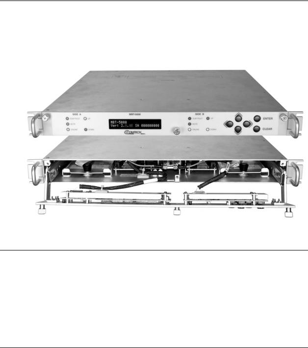
The MBT-5000, shown in Figure 1-1, features a drop-down front panel providing access to two upconverter modules, or two downconverter modules, or one of each.
Figure 1-1. Comtech EF Data MBT-5000 L-Band Up/Down Converter
1.2Functional Description
The MBT-5000’s 1RU-high, 19-inch wide chassis is designed for rack mounting into a standard 19-inch equipment rack. Handles installed on the front panel facilitate ease of installation into and removal from the equipment rack. The unit may be freestanding if desired.
All operator controls, indicators and displays for local and remote operation are located on the front panel of the MBT-5000. The drop-down design of the front panel provides user access to the two internal upconverter or downconverter modules.
1–1
MBT-5000 L-Band Up/Down Converter System |
MN-MBT5000 |
Introduction |
Revision 4 |
External interface connectors are located on the rear panel of the MBT-5000 chassis. External equipment, e.g., a modem, is connected to each internal converter module via a standard, off- the-shelf coaxial cable. A coaxial cable is also used to connect the output for each module to RF equipment either at the same location or at the antenna location.
When configured with the redundancy option, the system may contain two diode “OR-ed” internal power supplies for increased reliability and microprocessor-based Monitor and Control (M&C) functionality.
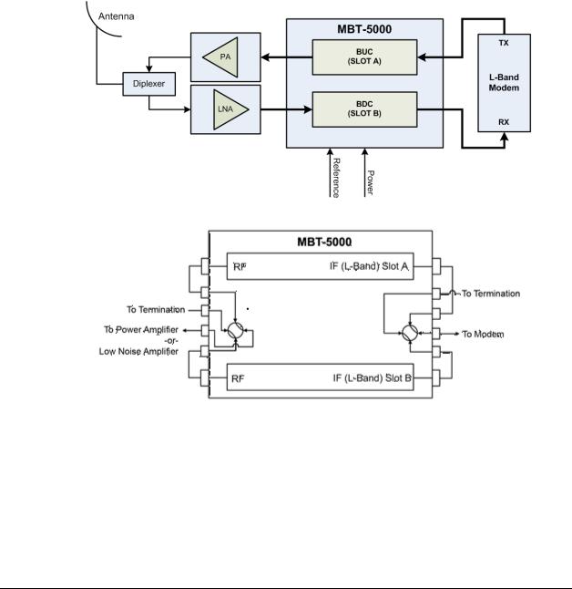
Figure 1-2 depicts the operational schematics for typical MBT-5000 L-Band Up/Downconverter System single thread (standalone) and redundant applications. For more information about the MBT-5000’s use in redundant applications, see Appendix B. MBT-5000 REDUNDANCY OPERATION.
MBT-5000 Single Thread (Standalone) Application
MBT-5000 Redundant Application (Single LNA Application shown)
Figure 1-2. MBT-5000 Operational Schematics
1–2
MBT-5000 L-Band Up/Down Converter System |
MN-MBT5000 |
Introduction |
Revision 4 |
1.3Features
•Meets or exceeds IESS-308/309
•Low phase noise
•20 dB gain adjustment
•Flexible configuration
•RF Band switching in minimal time without requiring tools
•Optional 1:1 Redundancy
1.3.1Block Upconverter (BUC-5000x)
The BUC-5000x field interchangeable upconverter module translates an L-Band input carrier to the desired output frequency (C-Band, X-Band, or Ku-Band) with an output level capable of driving a high-powered amplifier (HPA).
Note the following:
C-Band |
5850 to 6425 MHz |
(Invert optional) |
|
|
|
X-Band |
7900 to 8400 MHz |
|
|
|
|
Ku-Band |
13.75 to 14.50 GHz |
|
|
|
|
1.3.2Block Downcoverter (BDC-5000x)
The BDC-5000x field-interchangeable downconverter module translates a band-specific input frequency block (C-Band, X-Band, or Ku-Band) from the LNA down to L-Band (950 to 2000 MHz).
Note the following:
C-Band |
3400 to 4200 MHz (Non-Invert optional) |
|
|
X-Band |
7250 to 7750 MHz |
|
|
Ku-Band |
10.95 to 12.75 GHz |
|
|
1–3

MBT-5000 L-Band Up/Down Converter System |
MN-MBT5000 |
Introduction |
Revision 4 |
1.4Summary of Specifications
1.4.1 Physical & Environmental |
|
||
|
|
|
|
Weight |
|
15 lbs. (6.80 kg) Nominal |
|
Dimensions (excluding connectors) |
See Figure 1-3 |
||
Temperature |
Operating |
32º to 132.8ºF (0º to 56ºC) |
|
Non-operating (Storage) |
-58º to 158ºF (-50º to 70ºC) |
||
|
|||
Operational Altitude |
|
15,000 ft above sea level |
|
Shock |
|
Normal commercial shipping and handling |
|
|
|
|
|
1.4.2 |
Prime Power |
|
|
|
|
|
|
Voltage |
|
90 |
– 260 VAC, -48 VDC Optional |
Frequency |
|
47 to 63 Hz |
|
Dissipation |
|
60 |
Watts, typical |
|
|
|
|
1.4.3 Monitor & Control
Serial M&C Interface |
TIA/EIA-232, TIA/EIA-485, 4-wire |
|
DB-9F |
||
|
||
Alarm |
Form C, DB-9F |
|
Redundant Switch Connections |
SMA Female |
|
Remote Interface |
RJ-45 Ethernet |
|
|
|
1.4.4 Reference
External Input |
|
5 or 10 MHz 0 ±5 dBm optional |
|
|
BNC Female |
||
|
|
||
Output |
|
10 MHz Rear Panel |
|
|
BNC Female |
||
|
|
||
Internal |
Stability over Time |
±1x10⁻⁹/Day |
|
Stability over Temp |
±1x10⁻⁸/Day |
||
|
|||
|
|
|
1–4

MBT-5000 L-Band Up/Down Converter System |
MN-MBT5000 |
Introduction |
Revision 4 |
1.4.5BUC-5000x Block Upconverters
|
Model |
RF Output |
|
IF Input |
|
LO |
|
BUC-5000C |
5850-6425 MHz |
|
950-1525 MHz |
|
4900 MHz |
|
|
|
|
|
|
|
|
Optional |
5850-6650 MHz |
|
950-1750 MHz |
|
|
|
|
|
|
|
|
|
|
Optional |
5850-6725 MHz |
|
950-1825 MHz |
|
|
|
|
|
|
|
|
|
|
BUC-5000CI (Inverted) |
5850-6425 MHz |
|
950-1525 MHz |
|
7375 MHz |
|
BUC-5000X |
7900-8400 MHz |
|
950-1450 MHz |
|
6950 MHz |
|
|
|
|
|
|
|
Frequency Bands |
Optional |
7900-8400 MHz |
|
1000-1500 MHz |
|
6900 MHz |
|
|
|
|
|
|
|
BUC-5000Ku |
13.75-14.50 GHz |
|
950-1700 MHz |
|
12.80 GHz |
|
(by Model) |
|
|
||||
|
|
|
|
|
|
|
BUC-5000KuN |
14.00-14.50 GHz |
|
950-1450 MHz |
|
13.05 GHz |
|
|
|
|
||||
|
|
|
|
|
|
|
|
BUC-5000Ka |
30.00-31.00 GHz |
|
1000-2000 MHz |
|
29.00 GHz |
|
|
|
|
|
|
|
|
Optional |
27.50-28.50 GHz |
|
950-1950 MHz |
|
26.55 GHz |
|
|
|
|
|
|
|
|
Optional |
27.652-28.388 GHz |
|
1052-1788 MHz |
|
26.60 GHz |
|
|
|
|
|
|
|
|
Optional |
28.172-29.071 GHz |
|
972-1872 MHz |
|
27.20 GHz |
|
|
|
|
|
|
|
|
Optional |
28.50-29.50 GHz |
|
950-1950 MHz |
|
27.55 GHz |
|
|
|
|
|
|
|
|
Optional |
29.50-30.00 GHz |
|
950-1450 MHz |
|
28.55 GHz |
Input/Output Impedance |
|
50Ω |
|
|
|
|
Input Return Loss |
|
15 dB minimum |
|
|
|
|
Output Return Loss |
|
18 dB minimum |
|
|
|
|
Input Connector |
|
Type ‘N’ Female (Type ‘SMA’ for Redundancy option) |
|
|||
Output Connector |
|
Type ‘N’ Female (Type ‘SMA’ for Redundancy option) |
|
|||
|
|
30 dB nominal at minimum attenuation |
|
|||
Gain |
Full Band |
Constant Temp – ±1.0 dB |
|
|
|
|
|
|
|
|
|
||
0° to +50° C – ±0.25 dB |
|
|
|
|||
|
|
|
|
|
||
|
Per 40 MHz Slope |
.03 dB/MHz maximum |
|
|
|
|
Mute |
|
-60 dBc |
|
|
|
|
User Attenuation Range |
|
0 to 20 dB, in 0.25 dB steps |
|
|
|
|
Output Power, P1dB |
|
15 dBm minimum |
|
|
|
|
Noise Figure |
|
15 dB at minimum attenuation |
|
|
|
|
|
|
|
|
|
|
|
Intermodulation Distortion |
|
-50 dBc at 0 dBm Total Output |
|
|
|
|
Spurious (In-band) |
Carrier Related |
-60 dBc |
|
|
|
|
Non-Carrier Related |
-60 dBm |
|
|
|
||
|
|
|
|
|||
Phase Noise |
|
Meets or exceeds MIL-STD-188-164A |
|
|||
|
|
|
|
|
|
|
1–5

MBT-5000 L-Band Up/Down Converter System |
MN-MBT5000 |
Introduction |
Revision 4 |
1.4.6BDC-5000x Block Downconverters
|
|
Model |
RF Output |
|
IF Input |
|
LO |
|
|
BDC-5000C |
3400-4200 MHz |
|
950-1750 MHz |
|
5150 MHz |
|
|
|
|
|
|
|
|
|
|
BDC-5000CNI |
3625-4200 MHz |
|
1325-1900 MHz |
|
2300 MHz |
|
|
(Non-Inverting |
|
|
|||
|
|
|
|
|
|
|
|
|
|
BDC-5000X |
7250-7750 MHz |
|
950-1450 MHz |
|
6300 MHz |
|
|
|
|
|
|
|
|
|
|
Optional |
7250-7750 MHz |
|
1000-1500 MHz |
|
6250 MHz |
|
|
|
|
|
|
|
|
|
|
BDC-5000K (Standard) |
10.95-11.70 GHz |
|
950-1700 MHz |
|
10.00 GHz |
|
|
|
|
|
|
|
|
|
|
Switched LO |
11.70-12.20 GHz |
|
950-1450 MHz |
|
10.75 GHz |
|
|
|
|
|
|
|
|
Frequency Bands |
12.25-12.75 GHz |
|
950-1450 MHz |
|
11.30 GHz |
||
|
|
|
|||||
|
|
|
|
|
|
||
|
10.95-11.70 GHz |
|
950-1700 MHz |
|
10.00 GHz |
||
(by Model) |
OPTION 1 |
|
|
|
|
|
|
11.70-12.75 GHz |
|
950-2000 MHz |
|
10.75 GHz |
|||
|
|
|
|
|
|||
|
|
|
|
|
|
|
|
|
|
OPTION 2 |
10.70-11.70 GHz |
|
950-1950 MHz |
|
9.75 GHz |
|
|
|
|
|
|
|
|
|
|
11.70-12.75 GHz |
|
950-2000 MHz |
|
10.75 GHz |
|
|
|
|
|
|
|||
|
|
|
|
|
|
|
|
|
|
BDC-5000Ka |
20.20-21.20 GHz |
|
950-1950 MHz |
|
19.25 GHz |
|
|
|
|
|
|
|
|
|
|
Optional |
17.70-18.70 GHz |
|
950-1950 MHz |
|
16.75 GHz |
|
|
|
|
|
|
|
|
|
|
Optional |
17.852-18.588 GHz |
|
1052-1788 MHz |
|
16.80 GHz |
|
|
|
|
|
|
|
|
|
|
Optional |
18.372-19.271 GHz |
|
972-1871 MHz |
|
17.40 GHz |
|
|
|
|
|
|
|
|
|
|
Optional |
18.70-19.20 GHz |
|
950-1450 MHz |
|
17.75 GHz |
|
|
|
|
|
|
|
|
|
|
Optional |
19.20-20.20 GHz |
|
950-1950 MHz |
|
18.25 GHz |
Input/Output Impedance |
|
50Ω |
|
|
|
||
Input Return Loss |
|
18 dB minimum |
|
|
|
||
Output Return Loss |
|
15 dB minimum |
|
|
|
||
Input Connector |
|
Type ‘N’ Female (Type ‘SMA. for Redundancy option) |
|
||||
Output Connector |
|
Type ‘N’ Female (Type ‘SMA’ for Redundancy option) |
|
||||
|
|
|
35 dB nominal at minimum attenuation |
|
|||
Gain |
|
Full Band |
Contant Temp – ±0.25 dB |
|
|
|
|
|
|
|
|
|
|
||
|
0° to +50° C – ±1.0 dB |
|
|
|
|||
|
|
|
|
|
|
||
|
|
Per 40 MHz Slope |
.03 dB/MHz maximum |
|
|
|
|
Mute |
|
-60 dBc |
|
|
|
||
User Attenuation Range |
|
0 to 20 dB, in 0.25 dB steps |
|
|
|
||
Output Power, P1dB |
|
15 dBm minimum |
|
|
|
||
Noise Figure |
|
15 dB at minimum attenuation |
|
||||
Intermodulation Distortion |
|
-50 dBc at 0 dBm Total Output |
|
||||
Spurious (In-band) |
|
Carrier Related |
-60 dBc |
|
|
|
|
|
Non-Carrier Related |
-60 dBm |
|
|
|
||
|
|
|
|
|
|||
Phase Noise |
|
Meets or exceeds MIL-STD-188-164A |
|
||||
|
|
|
|
|
|
|
|
1–6

MBT-5000 L-Band Up/Down Converter System |
MN-MBT5000 |
Introduction |
Revision 4 |
1.5Dimensional Envelope
Figure 1-3. MBT-5000 Dimensional Envelope
1–7

MBT-5000 L-Band Up/Down Converter System |
MN-MBT5000 |
Introduction |
Revision 4 |
Notes:
1–8

Chapter 2. INSTALLATION
2.1Unpack and Inspect the Shipment
Figure 2-1. Unpacking and Inspecting the MBT-5000
The MBT-5000 L-Band Up/Down Converter System, its optional Installation and Operation Manual (otherwise available online at http://www.comtechefdata.com), and its power cord were packaged and shipped in a reusable cardboard carton containing protective foam spacing.
CAUTION – THIS EQUIPMENT CONTAINS PARTS AND ASSEMBLIES SENSITIVE TO
DAMAGE BY ELECTROSTATIC DISCHARGE (ESD). USE ESD PRECAUTIONARY PROCEDURES WHEN HANDLING THE EQUIPMENT.
2–1

MBT-5000 L-Band Up/Down Converter System |
MN-MBT5000 |
Installation |
Revision 4 |
Once opened, inspect the shipment:
Step Task
1Keep all shipping materials.
2Check the packing list to make sure the shipment is complete.
3Inspect the equipment for damage. If damage exists, immediately contact the carrier and Comtech EF Data to submit a damage report.
4Read the manual.
2.2Install the Unit Into a Rack Enclosure
Install the MBT-5000 in its assigned position in the rack enclosure (Figure 2-2). Use, as required:
•A standard rack-mounted shelf;
•User-supplied screws to secure the front panel to the rack enclosure threaded front mounting rails;
•Comtech EF Data’s optional KT/6228-2 (4”) or KT/6228-3 (10”) Rear-Mounting Support Brackets Kit (Figure 2-3);
•Comtech EF Data’s optional FP/SL0006 (26”), FP/SL0007 (24”), or FP/SL0008 (22”) Bearingless Rack Slide Set (Figure 2-4).
For information about custom rack enclosures and these optional installation accessories, contact Comtech EF Data Product Support.
CAUTION – OBSERVE THE FOLLOWING:
•CORRECT GROUNDING PROTECTION IS REQUIRED TO PREVENT PERSONAL INJURY AND EQUIPMENT DAMAGE.
You must make sure the ground stud on the rear panel of the unit is always connected to the protective earth.
•SUFFICIENT AIR VENTILATION IS REQUIRED – Make sure there is adequate air ventilation clearance inside the enclosure, especially at the side. In a rack system where there is high heat discharge, provide forced-air cooling with topor bottom-mounted fans or blowers.
•MAXIMUM AIR TEMPERATURE – Make sure the air temperature inside the enclosure never exceeds 50°C (122°F).
2–2

MBT-5000 L-Band Up/Down Converter System |
MN-MBT5000 |
Installation |
Revision 4 |
Feature |
Description |
1 |
Custom Rack Enclosure |
|
|
2 |
MBT-5000 Up/Down Converter System |
|
|
3 |
Standard Rack Shelving |
|
|
4 |
Rack Enclosure Threaded Front Rail (typical) |
5 |
Unit Front Panel |
6 |
User-supplied Screws |
|
|
Figure 2-2. Install the Unit into a Rack Enclosure
2–3

MBT-5000 L-Band Up/Down Converter System |
MN-MBT5000 |
Installation |
Revision 4 |
2.2.1Install the Optional Rear-Mounting Support Brackets Kit
Use the follwing tools to install the KT/6228-2 (4”) or KT/6228-3 (10”) Rear-Mounting Support Brackets Kit (Figure 2-3):
•A medium Phillips screwdriver
•A 5/32-inch SAE Allen Wrench
•An adjustable Crescent wrench.
Detail |
Description |
|
|
|
|
1 |
Back of Unit |
|
|
|
|
2 |
Rack Enclosure Threaded Rear Mounting Rail (typical) |
|
|||
|
|
|
|
|
|
Item |
Quantity per CEFD Kit |
Part Number |
Description |
||
KT/6228-2 |
KT/6228-3 |
||||
|
|
|
|||
1 |
2 |
2 |
HW/10-32SHLDR |
Shoulder Screw, #10 |
|
2 |
4 |
4 |
HW/10-32FLT |
Flat Washer, #10 |
|
3 |
2 |
2 |
HW/10-32SPLIT |
Lock Washer, #10 |
|
4 |
2 |
2 |
HW/10-32HEXNUT |
Hex Nut, #10 |
|
5 |
4 |
4 |
HW/10-32x1/2RK |
Bolt, #10, Rear Support Bracket |
|
6 |
2 |
– |
FP/6138-2 |
Bracket, Rear Support – 4” |
|
– |
2 |
FP/6138-3 |
Bracket, Rear Support – 10” |
||
|
|||||
Figure 2-3. Optional Rear-Mounting Support Brackets Kit Installation
2–4
Loading...