

Comelit FT SB 07 User Manual [en, de, fr]
FT/SB/07
I Citofonia e videocitofonia con cablaggio
a 2 fili non polarizzati.
GB Door and video entry phone systems
with unpolarised 2-wire cabling.
FParlophonie et visiophonie
avec câblage à 2 fils non polarisés.
D Gegensprech - und
Video - Gegensprechanlagen,
verdrahtet mit 2 ungepolten Drähten.
I •Evitare di porre i fili di montante in prossimità di cavi di alimentazione (220/380V).
•Connettere il telaio portamoduli a terra (vedi fig. 1).
•Effettuare l’installazione seguendo scrupolosamente le istruzioni fornite
dal costruttore ed in conformità alle normative vigenti.
•Tutti gli apparecchi devono essere destinati esclusivamente all’uso
per cui sono stati concepiti.
GB•Avoid placing the riser wires near power supply cables (220/380V).
• Connect the module-holder frame to earth (see fig. 1).
• Carry out installation following the manufacturer's instructions very carefully,
and in compliance with the laws in force.
• All the pieces of apparatus must only be used of the purposes
they have been built for.
F •Eviter de placer les fils de montant à proximité des câbles d’alimentation (220/380V).
•Connecter le cadre porte-modules à la terre (voir fig. 1).
•Effectuer l’installation en suivant scrupuleusement les instructions fournies par
le constructeur et en vous conformant aux réglementations en vigueur.
•Tous les appareils doivent être strictement destinés à l’emploi pour lequel ils
ont été conçus.
D •Die Drähte der Steigleitungen nicht in der Nähe
der Stromkabel (220/380 V) verlegen.
•Den Rahmen der Modulhalterung mit der
Erdleitung verbinden (siehe Abb.1).
• Die Installationen sind nach den Anweisungen
des Herstellers und gemäß den geltenden
Vorschriften gewissenhaft auszuführen.
•Alle Geräte dürfen ausschließlich nur zu dem
Zweck eingesetzt werden, für den sie
entwickelt worden sind.
Avvertenze
Warnings
Instructions
Hinweise
Fig. 1
1
Regole generali di installazione
General installation instructions
Règles générales d’installation
Allgemeine Installationsregeln
I • Connettere al massimo 100 derivati
per ogni montante.
• Connettere al massimo 3 derivati
con il medesimo codice utente.
• Il sistema può gestire al massimo
240 utenti.
• In impianti solo citofonici la
distanza massima di
funzionamento tra porta e
citofono più lontano è di 400mt
indipendentemente dal tipo di
cavo utilizzato e dalla tipologia
d’impianto.
GB •
Connect a maximum of 100 units
for each riser.
• Connect a maximum of 3 units with
each user code.
• The system can manage a
maximum of 240 users.
• In door entry phone only
systems, the maximum operating
distance between the door and
the telephone furthest away is
400mt regardless of the type of
cable used and the type of
system.
F•
Brancher au maximum 100 dérivés
pour chaque montant.
• Brancher au maximum 3 dérivés
avec le même code usager.
• Le système peut gérer 240 usagers
au maximum.
•
Dans des installations exclusivement
parlophoniques la distance
maximum de fonctionnement entre la
porte et le parlophone le plus éloigné
est de 400 m indépendamment du
type de câble utilisé et de la
typologie de l’installation.
D• Maximal 100 Abzweigungen je
Steigleitung anschließen.
• Maximal 3 Abzweigungen mit
demselben Benutzercode anschließen.
• Das System ist auf maximal 240
Benutzer ausgelegt.
• Bei reinen Gegensprechanlagen
darf der Abstand zwischen Tür
und Haustelefon maximal 400 m
betragen, unabhängig von der
Art des benutzten Kabels und
der Anlage.
Sezione conduttori di alimentazione (mm2) per il monitor e posto esterno
Cross-section of power supply conductors (mm2) for the monitor and the entrance unit
Section conducteurs d’alimentation (mm2) pour le moniteur et le poste extérieur
Querschnitt der Versorgungsleitungen (mm2) für den Monitor und die Außenstation
Alimentazione porta
Door power supply
Alimentation porte
Stromversorgung Tür
Alimentazione monitor con
art 1536 o 1212/B
Monitor power supply with art. 1536 or 1212/B
Alimentation moniteur avec art. 1536 ou 1212/B
Stromversorgung Monitor mit Art. 1536 oder 1212/B
Alimentazione monitor con art. 1212
Monitor power supply with art. 1212
Alimentation monitor avec art. 1212
Stromversorgung Monitor mit Art. 1212
0.22
0.22 1.00
1.00 1.50
0/12V~
0/+20
0/18V~
0/21V~
1.00
0.80
2.50
0.80
**
*
1.00 1.50 2.50
1 m 20 m 50 m 100 m 200 m 300 m

2
Regole d’installazione per impianti videocitofonici
Installation instructions for video door entry systems
Règles de montage pour les installations visiophoniques
Installationsregeln für Video-Gegensprechanlagen
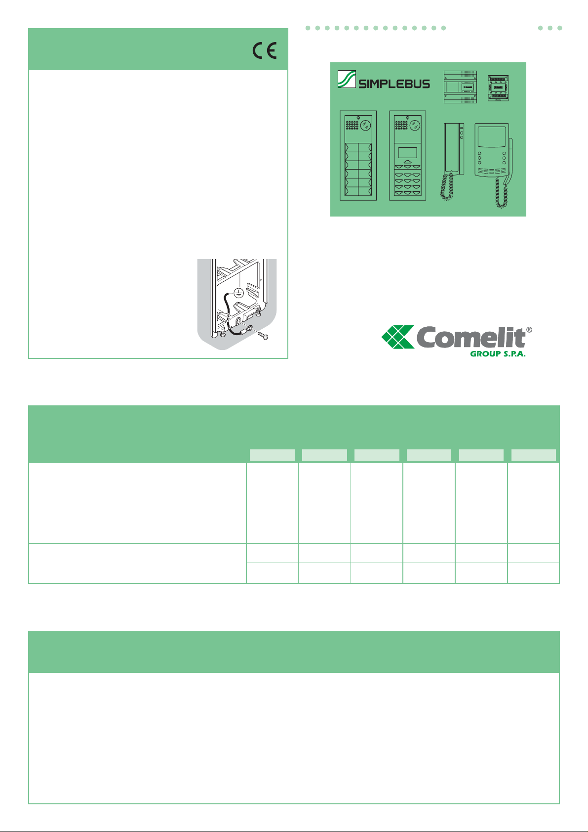
GB In the branches towards each user,
insert terminal
1214 supplied with
bracket 4614W/A or 4714W or 1561
on the riser.
Terminate each riser or branch with
art.
1216 provided with video
modules 4660 or with line amplifier
4833/A.
According to the cable used for the
riser, assess the maximum distance
which can be reached between the
video external unit and the furthest
branch
1214 (A1 in figure 2).
According to the cable used for the
branch, assess the maximum
distance which can be reached from
the monitor to the branch terminal
1214 (B in figure 2).
According to the cable used for the
riser, set closure of
art.
1216 as
indicated in figure 2, 3 and 6.
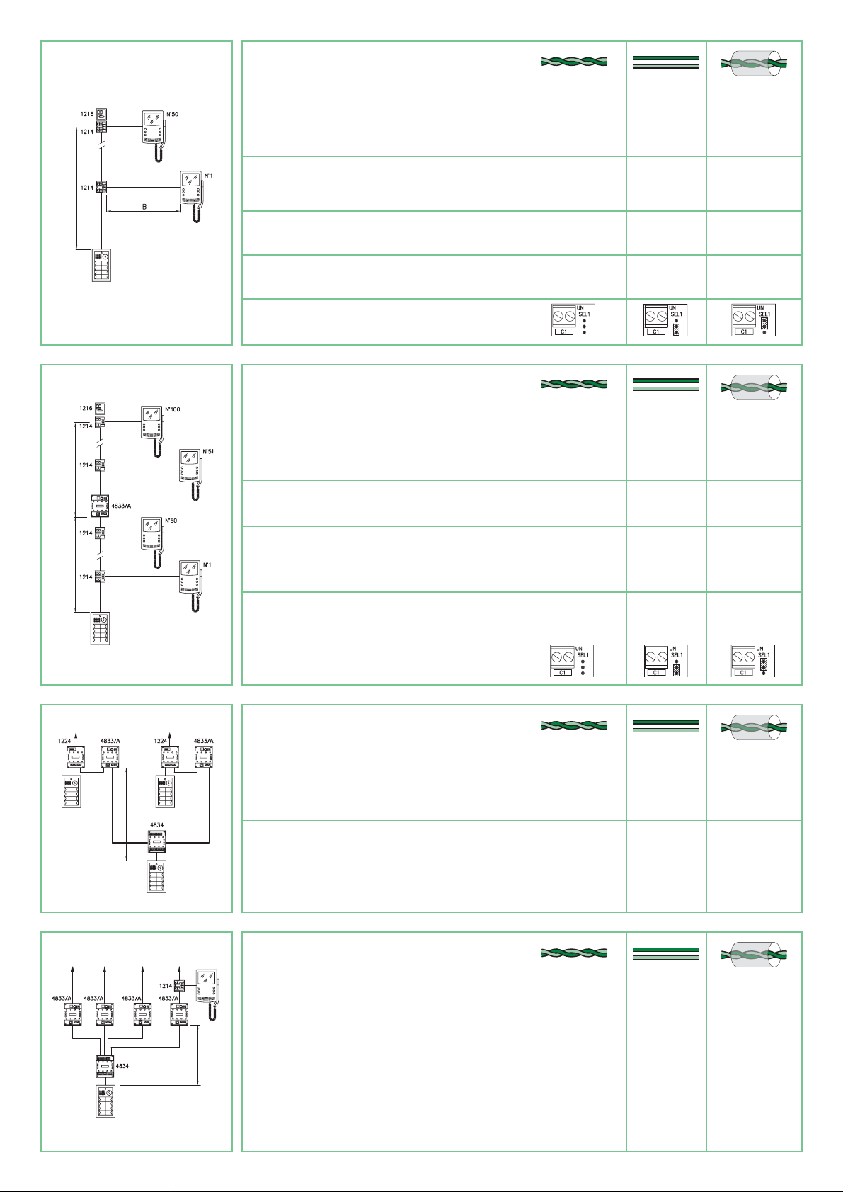
With more than
50 users it is always
necessary to insert a line amplifier
art. 4833/A (figure 3) on the riser.
Regardless of the number of users,
for riser lengths over limit A1
(figure 3) insert a line amplifier
art.
4833/A (figure 3).
Up to
3 line amplifiers
art.
4833/A
can be inserted on the riser to a
maximum total distance of 3xA1 and
in any case not more than 400mt.
In the case of systems with main and
secondary entrances
(figure 4) in
any case when the riser divides into
several branches
(figure 5), it is
necessary to use the line
concentrator art. 4834.
Art.
4834 allows a maximum of 10
branches.
When using the line concentrator, it
is necessary to insert an amplifier
art. 4833/A for each output of
art.
4834 (figure 4 and 5).
In the case of systems with
secondary entrances, it is advisable
to position amplifier
art.
4833/A near
the switching device
art.
1224
(figure 4).
According to the cable used for
connection, assess the maximum
distance which can be reached
between the video external unit and
the amplifier
art.
4833/A passing
through line concentrator
art.
4834
(C in fig. 4 and 5).
Collegamento in cascata in impianti videocitofonici
Cascade connection in video door entry systems
Connexion en cascade dans des installations visiophoniques
Kaskadenschaltung bei Video-Gegensprechanlagen
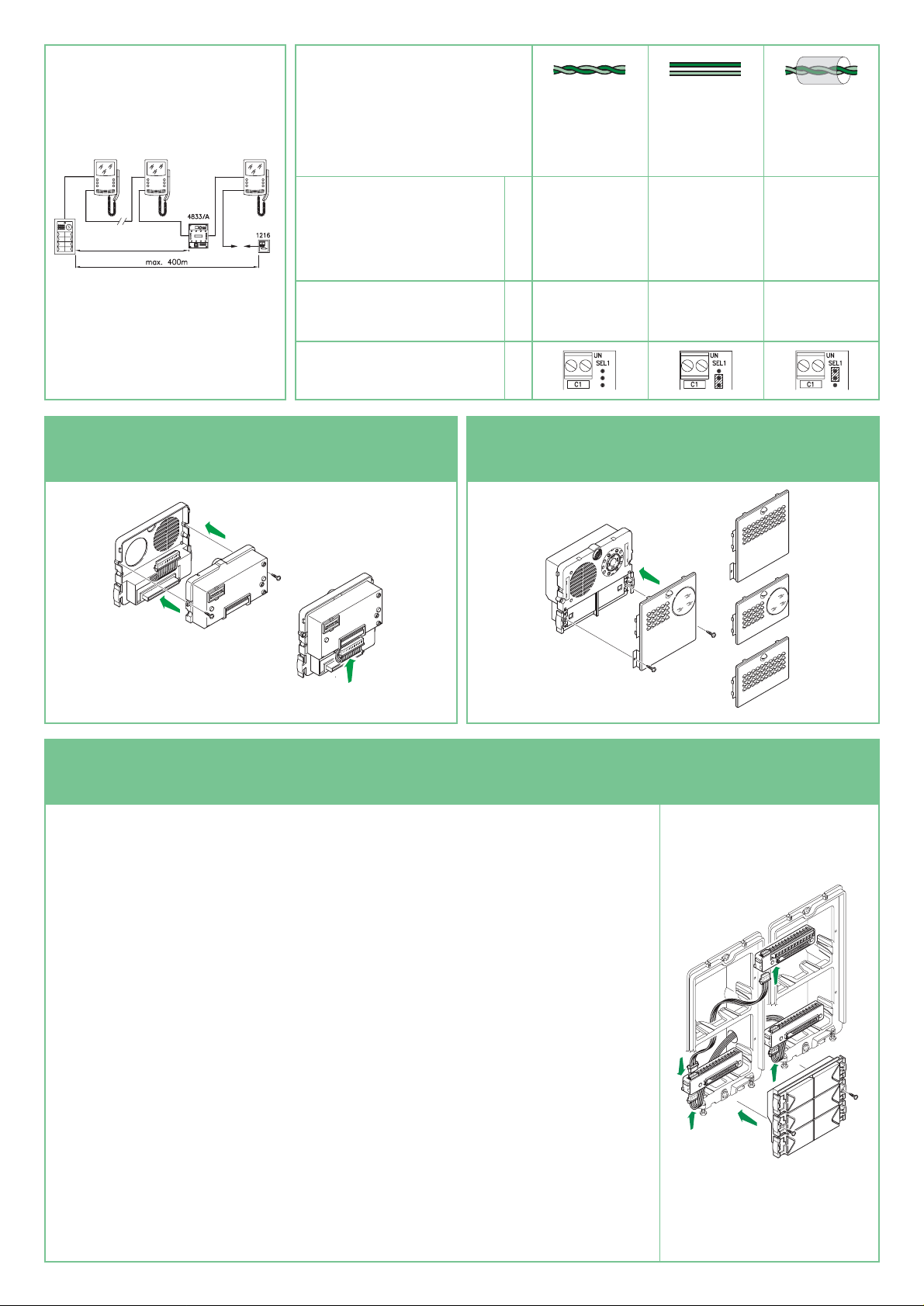
I
In alternativa all’uso dei morsetti di
derivazione art. 1214 e del
concentratore di linea è possibile
collegare gli utenti in cascata (figura 6).
In funzione dei cavi utilizzati per il
bus di montante valutare la distanza
massima raggiungibile dal posto
esterno video al monitor più lontano
(D in figura 6).Terminare il
montante con
l’art.
1216 (figura 6).
Indipendentemente dal numero di
utenti, per lunghezze di montante
superiori al limite
D (figura 6)
inserire un amplificatore di linea
art. 4833/A per una distanza
massima comunque non superiore
ai 400mt.
GB As an alter native to the use of
branch terminals
art.
1214 and line
concentrator, it is possible to connect
the users in cascade (figure 6).
According to the cables used for the
riser, assess the maximum distance
which can be reached from the video
external unit to the fur thest monitor
(D in figure 6).
Terminate the riser with
art.
1216
(figure 6). Regardless of the number
of users, for riser lengths over limit D
(figure 6), insert a line amplifier
art.
4833/A to a maximum distance in
any case of not over 400mt.
F Dans l’alternative à l’emploi des bornes
de dérivation art. 1214 et du
concentrateur de ligne, les usagers
peuvent être connectés en cascade
(figure 6). En fonction des câbles
utilisés pour le montant, évaluer la
distance maximum pouvant être
atteinte du poste extérieur vidéo au
moniteur le plus éloigné (D figure 6).
Terminer le montant avec l’art. 1216
(
figure 6
).Indépendamment du
nombre d’usagers pour des longueurs
de montant supérieures à la limite
D
(figure 6)
insérer un amplificateur de
ligne art. 4833/A pour une distance
maximum de toute façon jamais
supérieure à 400m.
D
An Stelle der Abzweigklemmen Art. 1214
und des Leitungskonzentrators können
die Benutzer in Kaskadenschaltung
miteinander verbunden werden (Abb. 6).
Auf Grundlage der für den Bus der
Steigleitung verwendeten Kabels muss
die maximal mögliche Entfernung
zwischen Video-Außenstation und dem
am weitesten entfernten Monitor
(D in
Abbildung 6) bewertet werden. Die
Steigleitung ist mit dem
Art. 1216
(Abbildung 6) abzuschließen. Bei
Steigleitungen, die länger sind als
maximal D (Abb. 6), ist unabhängig
von der Benutz erzahl ein Leitungsv erstärker
4833/A einzusetzen. Die Gesamtlänge
darf in jedem Fall 400 m nicht übersteigen.
D
Setzen Sie in jeden Abzweig zu einem
Benutzer in der Steigleitung die Klemme
1214 ein, die mit dem Sockel 4614W/A
oder 4714W oder 1561 geliefert wird.
Schließen Sie jede Steigleitung oder
Abzweig mit dem Art. 1216 ab, der mit
dem Videomodul 4660 oder dem
Leitungsverstärker
4833/A geliefert wird.
Auf Grundlage des für die Steigleitung
verwendeten Kabels muss die maximal
mögliche Entfernung zwischen VideoAußenstation und der am weitesten
entfernten Abzweigung 1214 (A1 in
Abbildung 2) bewertet werden.
Auf Grundlage des für den Abzweig
verwendeten Kabels muss die
maximal mögliche Entfernung des
Monitors vom
1214 bewertet werden
(B in Abbildung 2).
Auf Grundlage des verwendeten Kabels
für die Steigleitung muss der Abschluss
des
Art. 1216 wie in den Abbildungen
2, 3 und 6 erfolgen.
Bei mehr als 50 Benutzer n muss immer
ein Leitungsverstärker Art. 4833/A
eingesetzt werden (Abbildung 3).
Bei Steigleitungen, die länger sind als
maximal A1
(Abb. 3), ist unabhängig
von der Benutzerzahl ein
Leitungsverstärker 4833/A einzusetzen
(Abb. 3).
Auf der Steigleitung können auf einer
400 m nicht übersteigenden Länge von
3xA1 bis zu max. 3 Leitungsverstärkern
4833/A eingesetzt werden.
Bei Anlagen mit Haupt- und Nebentüren
(Abbildung 4), bzw.wenn die
Steigleitung sich in mehrere Abzweige
unterteilt (Abbildung 5), muss der
Leitungskonzentrator Art. 4834
verwendet werden.Der Art. 4834
erlaubt maximal 10 Abzweigungen.
Wenn man einen Leitungskonzentrator
verwendet, muss man an jeden
Ausgang des 4834 (Abb.4 und 5) einen
Verstärker art. 4833/A setzen.
Bei Anlagen mit Nebentüren sollte der
Verstärker
Art. 4833/A im Bereich des
Umschalters Art. 1224 montiert werden
(Abbildung 4).Auf Grundlage des für
den Anschluss verwendeten Kabels
muss die maximal mögliche Entfernung
zwischen Video-Außenstation und dem
Verstärker
4833/A mit Durchschleifen
des Leitungskonzentrators Art. 4834
(C in Abbildung 4 und 5) bewertet
werden.
F Dans les embranchements vers chaque
usager insérer sur le montant la borne
1214 fournie avec la bride 4614W/A ou
4714W ou l’art. 1561.
Terminer chaque montant ou chaque
embranchement par l’art. 1216 qui
équipe les modules vidéo 4660 ou
l’amplificateur de ligne
4833/A.
En fonction du câble utilisé pour le
montant évaluer la distance maximum
pouvant être atteinte entre le poste
extérieur video et l’embranchement le
plus éloigné 1214 (A1 figure 2).
En fonction du câble utilisé pour
l’embranchement évaluer la distance
maximum pouvant être atteinte entre
l’embranchement de montant
1214
et le moniteur (B figure 2).
En fonction du câble utilisé pour le
montant programmer la fermeture de
l’art. 1216 de la manière indiquée au in
figure 2, 3 et 6.Au-delà des 50 usagers
il est toujours nécessaire d’insérer sur le
montant un amplificateur de ligne
art. 4833/A (fig. 3).
Indépendamment du nombre d’usagers,
pour des longueurs de montant
supérieures à la limite A1
(figure 3)
insérer un amplificateur de ligne
art. 4833/A (figure 3).
Sur le montant, possibilité d’insérer
jusqu’à 3 amplificateurs de ligne
art. 4833/A pour une distance totale
maximum de 3xA1 et de toute façon
jamais supérieure à
400m.
Dans le cas d’installations avec des
entrées principales et secondaires
(figure 4) ou lorsque le montant se
divise en plusieurs embranchements
(figure 5), employer le concentrateur de
ligne
art. 4834.L’art. 4834 consent un
maximum de 10 embranchements.
Lors de l’utilisation du concentrateur de
ligne, il est nécessaire d’insérer un
amplificateur
art. 4833/A pour chaque
sortie de l’art. 4834 (figure 4).
Dans le cas d’installations avec des
entrées secondaires, il est conseillé de
mettre en place l’amplificateur
art.
4833/A en correspondance du
commutateur art. 1224 (figure 4).En
fonction du câble utilisé pour la
connexion, évaluer la distance
maximum pouvant être atteinte entre
l’entrée vidéo et l’amplificateur
art.
4833/A en passant par le concentrateur
de ligne art. 4834 (C in figure 4 et 5).
I Nelle diramazioni verso ogni utente
inserire sul montante il morsetto
1214
fornito a corredo della staffa 4614W/A
o 4714W o del 1561.
Terminare ogni montante o
diramazione con l’art. 1216 fornito a
corredo del modulo video 4660
o dell’amplificatore di linea 4833/A.
In funzione del cavo utilizzato
per il montante valutare la distanza
massima raggiungibile tra posto
esterno video
e la diramazione
1214 più lontana
(A1 in figura 2).
In funzione del cavo usato per la
diramazione valutare la distanza
massima del monitor dal
1214
(B in figura 2).
In funzione del cavo usato per
il montante impostare la chiusura
dell’
art.
1216 come indicato
nelle figure 2, 3 e 6.
Oltre i 50 utenti è sempre necessario
inserire sul montante un amplificatore
di linea
art. 4833/A (figura 3).
Indipendentemente dal numero di
utenti, per lunghezze di montante
superiori al limite A1 (
figura 3
)
inserire un amplificatore di linea
art.
4833/A (figura 3)
.
Sul montante, è possibile inserire fino a
3 amplificator i di linea art. 4833/A per
una distanza massima totale di 3xA1 e
comunque non superiore ai 400mt.
Nel caso di impianti con porte principali
e secondarie
(figura 4) o comunque
quando il montante si divide in più
diramazioni (figura 5) è necessario
impiegare il concentratore
di linea art. 4834.
L’art. 4834 consente
al massimo 10 diramazioni.
Utilizzando il concentratore
di linea è necessario inserire
un amplificatore
art. 4833/A per ogni
uscita del 4834 (fig. 4 e 5).
Nel caso di impianti con porte
secondarie è consigliabile posizionare
l’amplificatore
art. 4833/A in
corrispondenza dello scambio
art. 1224 (figura 4). In funzione del
cavo usato per il collegamento
valutare la distanza massima
raggiungibile tra il posto esterno
video e l’amplificatore
4833/A
passando per il concentratore di
linea art. 4834 (C in figura 4 e 5).
3
Doppino telefonico twistato o cavo
Comelit 2x0,5 mm2art. 4576
Telephone twisted pair or Comelit
cable 2x0.5 mm2art. 4576
Boucle téléphonique twistée ou
câble Comelit 2x0.5 mm
2
art. 4576
Einfacher Klingeldraht oder
Comelit Kabel 2x0,5 mm2Art. 4576
Cavo non intrecciato
Unbraided cable
Câble non retors
Nicht geflochtenes Kabel
Cavo intrecciato e schermato
Braided and shielded cable
Câble retors et blindé
Geflochtenes u.
abgeschirmtes Kabel
150 m 100 m 80 m
40 m 20 m 15 m
50 50 50
A1
A1
A1
A2
Fig. 3
C
Fig. 4
Fig. 2
Distanza massima tra posto esterno video e diramazione art. 1214 più lontana.
Maximum distance between the video entrance unit
and the furthest branch terminal
art. 1214.
Distance maximum entre le poste extérieur vidéo et la borne
art. 1214 la plus éloignée.
Maximale Entfernung zwischen Video Außenstation und Abzweig Art.1214
Distanza massima del monitor dal art. 1214.
Maximum distance between monitor and branch terminal
art. 1214.
Distance maximum du moniteur de la borne
art. 1214.
Maximale Entfernung des Monitors zur Klemme
Art. 1214
N° massimo di utenti
Maximum user n°
Nombre maximum d’usagers
Maximale Benutzerzahl
Posizione selettore su terminazione di linea
art. 1216.
Position of selector on termination of line
art. 1216.
Position du sélecteur sur la borne de ligne
art. 1216.
Position des Wählschalters auf dem Leitungsabschluss
Art. 1216
1216
B
Doppino telefonico twistato o cavo
Comelit 2x0,5 mm2art. 4576
Telephone twisted pair or Comelit
cable 2x0.5 mm2art. 4576
Boucle téléphonique twistée ou
câble Comelit 2x0.5 mm
2
art. 4576
Einfacher Klingeldraht oder
Comelit Kabel 2x0,5 mm
2
Art. 4576
Cavo non intrecciato
Unbraided cable
Câble non retors
Nicht geflochtenes Kabel
Cavo intrecciato e schermato
Braided and shielded cable
Câble retors et blindé
Geflochtenes u.
abgeschirmtes Kabel
150 m 100 m 80 mC
Distanza massima tra posto esterno video principale e amplificatore art. 4833/A.
Maximum distance between the main video entrance unit
and the amplifier
art. 4833/A.
Distance maximum entre le poste extérieur vidéo principale
et l’amplificateur
art. 4833/A.
Maximale Entfernung zwischen Haupt-Video Außenstation und Verstärker
Art. 4833/A
C
Fig. 5
Doppino telefonico twistato o cavo
Comelit 2x0,5 mm
2
art. 4576
Telephone twisted pair or Comelit
cable 2x0.5 mm2art. 4576
Boucle téléphonique twistée ou
câble Comelit 2x0.5 mm2art. 4576
Einfacher Klingeldraht oder
Comelit Kabel 2x0,5 mm
2
Art. 4576
Cavo non intrecciato
Unbraided cable
Câble non retors
Nicht geflochtenes Kabel
Cavo intrecciato e schermato
Braided and shielded cable
Câble retors et blindé
Geflochtenes u.
abgeschirmtes Kabel
150 m 100 m 80 mC
Distanza massima tra posto esterno video
e amplificatore art. 4833/A della diramazione di montante.
Maximum distance between the video entrance unit
and the branch amplifier
art. 4833/A.
Distance maximum entre le poste extérieur vidéo
et l’amplificateur
art. 4833/A du montant.
Maximale Entfernung zwischen Video Außenstation und Verstärker
Art. 4833/A
des Steigleitungsabzweigs
Doppino telefonico twistato o cavo
Comelit 2x0,5 mm2art. 4576
Telephone twisted pair or Comelit
cable 2x0.5 mm2art. 4576
Boucle téléphonique twistée ou
câble Comelit 2x0.5 mm
2
art. 4576
Einfacher Klingeldraht oder
Comelit Kabel 2x0,5 mm2 Art. 4576
Cavo non intrecciato
Unbraided cable
Câble non retors
Nicht geflochtenes Kabel
Cavo intrecciato e schermato
Braided and shielded cable
Câble retors et blindé
Geflochtenes u.
abgeschirmtes Kabel
150 m 100 m 80 m
150 m 100 m 80 m
50+50 50+50 50+50
A1
Distanza massima tra posto esterno video e amplificatore art. 4833/A.
Maximum distance between the video entrance unit and the amplifier art. 4833/A.
Distance maximum entre le poste extérieur vidéo et l’amplificateur art. 4833/A.
Maximale Entfernung zwischen Video Außenstation und Verstärker Art. 4833/A
Distanza massima tra amplificatore art. 4833/A e diramazione art. 1214 più lontana.
Maximum distance between the amplifier art. 4833/A and the fur thest
branch terminal art. 1214.
Distance maximum entre l’amplificateur art. 4833/A et la borne art. 1214 la plus éloignée.
Maximale Entfernung zwischen Verstär ker
art.
4833/A und dem weitesten
entfernten Abzweig Art. 1214
N° massimo di utenti
Maximum user n°
Nombre maximum d’usagers
Maximale Benutzerzahl
Posizione selettore su terminazione di linea
art. 1216.
Position of selector on termination of line art. 1216.
Position du sélecteur sur la borne de ligne art. 1216.
Position des Wählschalters auf dem Leitungsabschluss Art.1216
1216
A2
4
Montaggio e collegamento gruppo audio/video
How to mount and connect the audio/video group
Comment monter et relier le groupe audio/vidéo
Montage und Verbindung der Audio-Video Gruppe
Montaggio /Smontaggio frontalini
How to insert and remove front panels
Comment insérer et enlever les façades avant
Montage / Demontage der Frontplatte
Programmazione pulsanti con gruppo audio e video art. 1602, art.4660 e moduli art. 3323/4 e 3323/6
Programming push buttons with audio an video groups art. 1602, art.4660 and p.b. modules art. 3323/4 - 3323/6
Programmation des touches avec les groupe audio et vidéo art. 1602, art 4660 et les modules art. 3323/4-3323/6
Programmierung der Tasten mit der Audio - und Videogruppe Art. 1602, art. 4660 und den Modulen art. 3323/4 und 3323/6
I1.Connettere le morsettiere
dei moduli 3323/4 e 3323/6
tra loro e con la morsettiera
del gruppo 4660 o 1602
utilizzando gli appositi
cavetti.Inserire i moduli
3323/4 e 3323/6 sulle
relative morsettiere
(figura 9).
2. Sulla morsettiera del
modulo 4660 o 1602
collegare l’alimentazione su
~~ , connettere PR a -e spostare P/O da OCC a
V+
(figura 10)
utilizzando i
jumper presenti sulla
morsettiera stessa.
Connettere la morsettiera al
modulo 4660 o 1602
assemblato come indicato
precedentemente.
(attenzione i moduli 3323/4
e 3323/6 da programmare
devono essere già
posizionati)
(figura 10)
.
NOTA: per il collegamento
tra la morsettiera e il
modulo
4660 o 1602 in fase
di programmazione è
possibile usare il cavetto
art. 3309 disponibile come
accessorio opzionale
(figura 11).
GB 1. Connect terminal boards
of p.b.modules art. 3323/4
and 3323/6 to each other
and to the terminal board of
unit
4660 or 1602 by means
of provided cables.Insert
modules
3323/4 and 3323/6
to relative terminal boards
(see picture 9).
2. On the terminal board of
unit art.
4660 or 1602
connect power supply on ~~
PR to – and move P/O from
OCC to V+ by means of
relative jumpers
(see picture
10)
. Connect the terminal
board to the assembled unit
art 4660 or 1602 as shown
in pictures 7 and 8.
Attention: modules
art.
3323/4 and 3323/6 must
be already located
before programming
(see picture 10).
NOTE: you can use cable
art. 3309 (available as
optional accessory) to
connect the terminal board
to units 4660 or 1602
during programming
(see picture 11).
F1.Connecter les borniers
des modules
art. 3323/4 et
3323/6 entre eux et avec le
bornier du module
4660
ou 1602 en utilisant les
petits câbles appropriés.
Insérer les modules
3323/4
et 3323/6 sur les borniers
dédiées
(fig. 9)
.
2. Sur le bornier du groupe
4660 ou 1602 connecter
l’alimentation sur
~~ PR sur
– et déplacer P/O de OCC
à V+
(figure 10)
en utilisant
les petits ponts qui sont sur
le bornier même. Connecter
le bornier au groupe
4660
ou 1602 assemblé comme
illustré précédemment
(fig. 7 et 8)
.
Attention: les modules
3323/4 et 3323/6 à
programmer doivent être
déjà positionnés
(figure 10).
NOTE :pour la connexion
entre bornier et groupe
4660
ou 1602 en phase de
programmation il est possible
d’utiliser le petit câble
art.
3309
, disponible comme
accessoire optionnel
(fig. 11).
D1.Die Klemmleisten der Module
Art. 3323/4 und Art. 3323/6
untereinander und mit der
Klemmleiste der Gruppe
4660 oder
1602 verbinden, indem man die
dazu bestimmten Kabel ver wendet.
Die Module Art.
3323/4 und Art.
3323/6 in die jeweiligen Klemmleisten
einfügen (Abbildung 9).
2
.Auf der Klemmleiste des
Moduls Art.
4660 oder Art. 1602
das Netzgerät mit ~~ und PR
mit – verbinden und P/O von
OCC auf
V+ (Abbildung 10)
versetzen, indem man die
Schaltbrücken verwendet die auf
der Klemmleiste selbst vorhanden
sind verwendet.Die Klemmleiste
mit dem Modul
4660 oder 1602
verbinden das,
wie vorher gezeigt,
zusammengebaut wurde. (Achtung
die zu programmierenden Module
3323/4 und 3323/6 müssen schon
in Position sein)
(Abbildung 10).
ANMERKUNG: Zur Verbindung
zwischen der Klemmleiste und
dem Modul
4660 oder 1602 ist
es in der Programmierungsphase
möglich das Kabel
Art. 3309,
das als zusätzliches Zubehör
erhältlich ist
(Abbildung 11),
zu verwenden.
Fig. 9
200 m 130 m 100 m
100 100 100
D
1216
Distanza massima tra posto esterno video e monitor più
lontano o amplificatore art. 4833/A in collegamento in cascata.
Maximum distance between the video entrance unit and the
furthest monitor or amplifier
art. 4833/A in cascade connection.
Distance maximum entre le poste extérieur et le moniteur le plus
éloigné ou l’amplificateur art. 4833/A avec connexion en cascade.
Maximale Entfernung zwischen Video Außenstation und am weitesten
entfernten, in Kaskade geschaltetem Monitor oder V erstärker
Art. 4833/A.
N° massimo utenti
Maximum user n°
Nombre maximum d’usagers.
Maximale Benutzerzahl
Posizione selettore su terminazione di linea
art. 1216.
Position of selector on termination of line
art.1216.
Position du sélecteur sur la borne de ligne
art.1216.
Position des Wählschalters auf dem Leitungsabschluss Art.1216
D
Fig. 6
Fig. 7 Fig. 8
Doppino telefonico twistato o cavo
Comelit 2x0,5 mm
2
art. 4576
Telephone twisted pair or Comelit
cable 2x0.5 mm
2
art. 4576
Boucle téléphonique twistée ou
câble Comelit 2x0.5 mm2art. 4576
Einfacher Klingeldraht oder
Comelit Kabel 2x0,5 mm
2
Art. 4576
Cavo non intrecciato
Unbraided cable
Câble non retors
Nicht geflochtenes Kabel
Cavo intrecciato e schermato
Braided and shielded cable
Câble retors et blindé
Geflochtenes u.
abgeschirmtes Kabel
 Loading...