

CITIZEN BD2-1221 User's Manual

User’s Manual
CONTROL BOARD FOR LT-122x/132x
MODEL
Rev. 02 Newly issued Jun. 10th, 2001
BD2-1220/1221

REVISION
Rev.No. Date Content
Rev.02 Jun. 10th, 2001 Newly issued
i
GENERAL PRECAUTIONS
Prior to using the Control Board BD2-1220/1221, be sure to read this User’s
Manual thoroughly. Please keep it handy so that you can refer to it whenever
necessary.
1. The information contained herein may be changed without prior notice.
2. Reproduction of part or all of the User’s Manual without permission is strictly prohibited.
3. Never service, disassemble, or repair parts that are not described in the User’s Manual.
4. Note that CBM shall not be responsible for any damages attributable to incorrect
operation/handling or improper operation environments, which are not specified in the
User’s Manual.
5. Operate this control board only in the manners as described in the User’s Manual;
otherwise, accidents or problems could possibly occur.
6. Data are basically temporary; they cannot be stored or saved for a long time or
permanently. Please note that CBM shall not be responsible for any damages or lost
profits resulting from the loss of data attributable to accidents, repairs, tests, and so on.
7. If you have any questions, or notice any clerical errors or omissions regarding the
information in the User’s Manual, please contact your CBM dealer.
8. Please note that CBM shall not be responsible for any results or effects resulting from
operation of this control board even if the information in the User’s Manual is properly
observed.
SAFETY PRECAUTIONS
— WHICH SHOULD BE STRICTLY OBSERVED
In order to help prevent safety hazards to operators or any other persons and
damages to property, special warning symbols are used in this User’s
Manual to indicate important items to be strictly observed. The following
describes possible hazards that could result from abuse of this product or
negligence of the safety cautions:
WARNING
CAUTION
This is a symbol mark used to alert your attention to important items.
Negligence of the precautions indicated by this symbol may
result in death or serious injuries.
Negligence of the precautions indicated by this symbol may
result in injuries or damages to property.
ii
WARNING
● Never handle the Control Board BD2-1220/1221 in the manners descried below;
otherwise, it may be damaged, get out of order or overheated, possibly causing smoke,
fire or electric shock.
● If the control board is damaged or breaks down, be sure to turn off the power, disconnect
the power plug from the wall outlet, and contact your CBM dealer.
• Do not allow the control board to be subjected to any strong impact or shock, such as stamping, hitting,
dropping, and the like.
• Install the control board in a well-ventilated place. Do not use the control board in such a manner that its
ventilation slots are blocked.
• Do not install the control board in a place like a laboratory where chemical reactions are expected, or in a
place where saltish gases are present in the atmosphere.
• Use the control board only on the specified voltage and frequency. Otherwise, fire or smoke generation may
occur.
• Do not connect/ disconnect the power cord or data cable by holding the cable.
Do not pull or carry the control board in such a manner that undesirable force is applied to the cables.
• Do not drop or insert any foreign substances, such as paper clips or pins, into the control board.
• Do not spill any liquid on or spray any chemical-containing liquid over the control board. If you spilled water
or any other liquid onto this product, immediately shut off power supply and contact your CBM dealer.
• Do not disassemble or modify the control board in any manner; otherwise, a fire or electric shock may result.
• Do not place the equipment where it can be easily touched during operation. Otherwise, possible shock or
static build-up may cause fire or damage to the control board electronics.
PRECAUTIONS FOR INSTALLATION
• Do not use or store the Control Board BD2-1220/1221 in a place exposed to heat of fire, moisture or direct
sunlight, or in a place where the prescribed operating temperature and humidity are not met, or in a place
exposed to oily mist, iron powder or dust; otherwise, the control board may get out of order, emit smoke or
catch fire.
• Do not install the control board in a place like a laboratory where chemical reactions are expected, or in a place
where saltish gases are present in the atmosphere; otherwise, there may occur a danger of fire or electric
shock.
• Install the control board on a horizontal, sturdy table in a place provided with proper ventilation and free from
any vibration. Do not install in an unstable place, as this may lead to equipment failure.
• Do not use the control board near a radio or television receiver. Avoid sharing an electrical outlet with a radio or
television receiver, or this may cause a reception problem.
• Never connect the grounding cable to a gas pipe, or this may lead to a danger of explosion.
• Be sure to turn off the power of the control board and the host computer connected before connecting or
disconnecting the cables; always hold both plug and cable. Do not use or wire the control board in such a
manner that an undesirable load is applied to the cables.
• Connect the connector cables correctly and securely.
• Use shielding wires or twist paired wires for signal lines in order to minimize the effects from noise. Do not
extend the data cable too long.
• Do not connect the data cable to noisy equipment.
• In case of emergency, always place the control board so that it is easily disconnected from the power source.
iii
PRECAUTIONS FOR HANDLING
Observe the following precautions to use the Control Board BD2-1220/1221 correctly and
avoid troubles from occurring.
• Use only the rated supply voltage specified for this product.
• Exercise care not to drop any metallic foreign object onto this product.
• Do not spill any liquid on the control board, or spray it with any chemical-containing liquid.
• Do not stamp on, drop, hit, or impart any strong shock to the control board.
• Wirings to other devices should be carefully established to avoid cross connections which may damage not
only the control board itself, but other system devices attached to it.
• This product should only be used with the specified peripheral devices.
• Do not use the control board in a place where it can easily come into contact with the hands.
• This product contains devices that are sensitive to electrostatic damage. When handling, keep any source of
static electricity away from the control board.
• Do not connect this product to, or install it in the vicinity of, any equipment that is the source of
electromagnetic noise. The control board may have an adverse affect on any attached peripherals. We
recommend you use some kind of noise insulating device with this equipment.
• This product can be reconfigured for non-default operation parameters. When using a soldering iron for
jumper reconnections, exercise care not to damage the adjacent parts. Also be sure to turn off the control
board before launching reconfiguration work.
• When reshipping this product, carefully pack it to protect it from vibration, deformation, or electrostatic
damage possible in transit.
To prevent injuries and associated damages:
• Should any abnormal condition occur while the control board is operating, stop it immediately and
disconnect the power plug from the wall outlet.
• This product may partially heats up as a result of extended use. Allow a sufficient time to cool off before
starting repair or maintenance work.
• In case of trouble, never attempt to repair the control board yourself. Be sure to call your dealer for servicing.
• Before using this product for the first time, please read the instructions throughout this manual.
iv

THE TABLE OF CONTENTS
1. GENERAL OUTLINE ........................................................................................................................ 1
1.1 Features..................................................................................................................................................................... 1
1.2 Before using.............................................................................................................................................................. 1
2. BASIC SPECIFICATIONS ................................................................................................................ 2
2.1 Model Classification................................................................................................................................................. 2
2.2 Basic Specifications.................................................................................................................................................. 3
2.3 Print Paper Specifications......................................................................................................................................... 4
2.4 Thermal Print Head and Peripheral Devices ............................................................................................................ 4
3. INTERCONNECTION ....................................................................................................................... 5
3.1 Interface Connector (CN1) ....................................................................................................................................... 5
3.1.1 Pin Description .................................................................................................................................................. 5
3.1.2 Example of Power Connections ........................................................................................................................ 6
3.2 Print Head Interface Connector (CN2) ....................................................................................................................... 7
3.2.1 Pin Description .................................................................................................................................................. 7
3.2.2 Compatible FFC Cable ...................................................................................................................................... 7
3.3 Head-Up and Paper End Sensor Connectors (CN3 & CN7) .................................................................................... 8
3.4 Motor Connector (CN4) ........................................................................................................................................... 8
3.5 Auto Cutter Connector (CN5) .................................................................................................................................. 8
3.6 Paper Near-End Sensor Connector (CN6) *Option.......................................................................................... 9
3.6.1 Pin Description .................................................................................................................................................. 9
3.6.2 Reference Schematic Diagram .......................................................................................................................... 9
4. CONFIGURING THE CONTROL BOARD FUNCTIONS ......................................................... 10
4.1 DIP Switches .......................................................................................................................................................... 10
4.2 Jumpers................................................................................................................................................................... 10
4.3 Preset Jumper.......................................................................................................................................................... 11
5. POWER SUPPLY .............................................................................................................................. 12
5.1 Specifications ......................................................................................................................................................... 12
5.2 Precautions ............................................................................................................................................................. 12
6. PARALLEL INTERFACE................................................................................................................ 13
6.1 Specifications ......................................................................................................................................................... 13
6.2 Description of Input and Output Signals ................................................................................................................ 14
6.2.1 Input Signals .................................................................................................................................................... 14
6.2.2 Output Signals ................................................................................................................................................. 14
6.2.3 Power related signal ........................................................................................................................................ 14
6.3 Electrical Characteristics ........................................................................................................................................ 14
6.4 Timing Chart (Compatibility Mode) ...................................................................................................................... 15
v

6.5 Data Reception Control .......................................................................................................................................... 15
6.6 Buffering................................................................................................................................................................. 15
6.7 Connections to Parallel Port ................................................................................................................................... 16
7. SERIAL INTERFACE ...................................................................................................................... 17
7.1 Specifications ......................................................................................................................................................... 17
7.2 Description of Input and Output Signals ................................................................................................................ 18
7.3 Electrical Characteristics ........................................................................................................................................ 18
7.4 Data Structure ......................................................................................................................................................... 19
7.5 Error Detection ....................................................................................................................................................... 19
7.6 Data Reception Control .......................................................................................................................................... 20
7.7 Buffering................................................................................................................................................................. 20
7.8 Connections to Serial Port ...................................................................................................................................... 20
8. ERROR HANDLING........................................................................................................................ 21
8.1 List of Error indications.......................................................................................................................................... 21
8.2 Error Details ........................................................................................................................................................... 22
9. SPECIAL FUNCTIONS ................................................................................................................... 23
9.1 Page Print Mode ..................................................................................................................................................... 23
9.2 Test Printing ............................................................................................................................................................ 23
9.3 Hexadecimal Dump ................................................................................................................................................ 23
9.4 Software Revision .................................................................................................................................................. 24
9.5 Registering User-Defined Fonts and Logos ........................................................................................................... 24
10. PRINT CONTROL COMMANDS ................................................................................................ 25
11. BLOCK DIAGRAM ........................................................................................................................ 29
12. OUTLINE DRAWINGS FOR CONTROL BOARD.................................................................... 30
APPENDIX 1. DESCRIPTION OF PAGE MODE ..............................................................................A
APPENDIX 2. IDENTIFICATION OF SEND STATUS......................................................................C
APPENDIX 3. DEVICE ID ....................................................................................................................D
APPENDIX 4. CHARACTER CODES TABLE...................................................................................E
1 Code page .................................................................................................................................................................... E
2 International Character Codes Table .......................................................................................................................... H
MAINTENANCE AND SER VICE .........................................................................................................I
vi
1. GENERAL OUTLINE
The BD2-1220/1221 Control Board is designed to operate the LT-1220/21 or LT-1320/21 Thermal Print
Mechanism from a PC. It incorporates maximum versatility that makes it applicable to diverse purposes.
Before using this product for the first time, read the instructions throughout this manual.
1.1 Features
(1) Ultra-compact design.
(2) Selectable serial or parallel printer interface.
(3) Support for both 80 mm (LT-132x) and 58 mm (LT-122x) print heads.
(4) Built-in input buffer.
(5) Bar-code Printing (Possible using special commands).
(6) Page Mode, which allows you to lay out pages freely.
(7) Registration of user-defined characters and logos into flash memory.
(8) Auto cutter mechanism provided as a standard unit.
(9) Paper End and Paper Near End sensors incorporated.
(10) Mounting hole geometry identical to those on the LT-122x.
BD2-1220/1221 User’s Manual
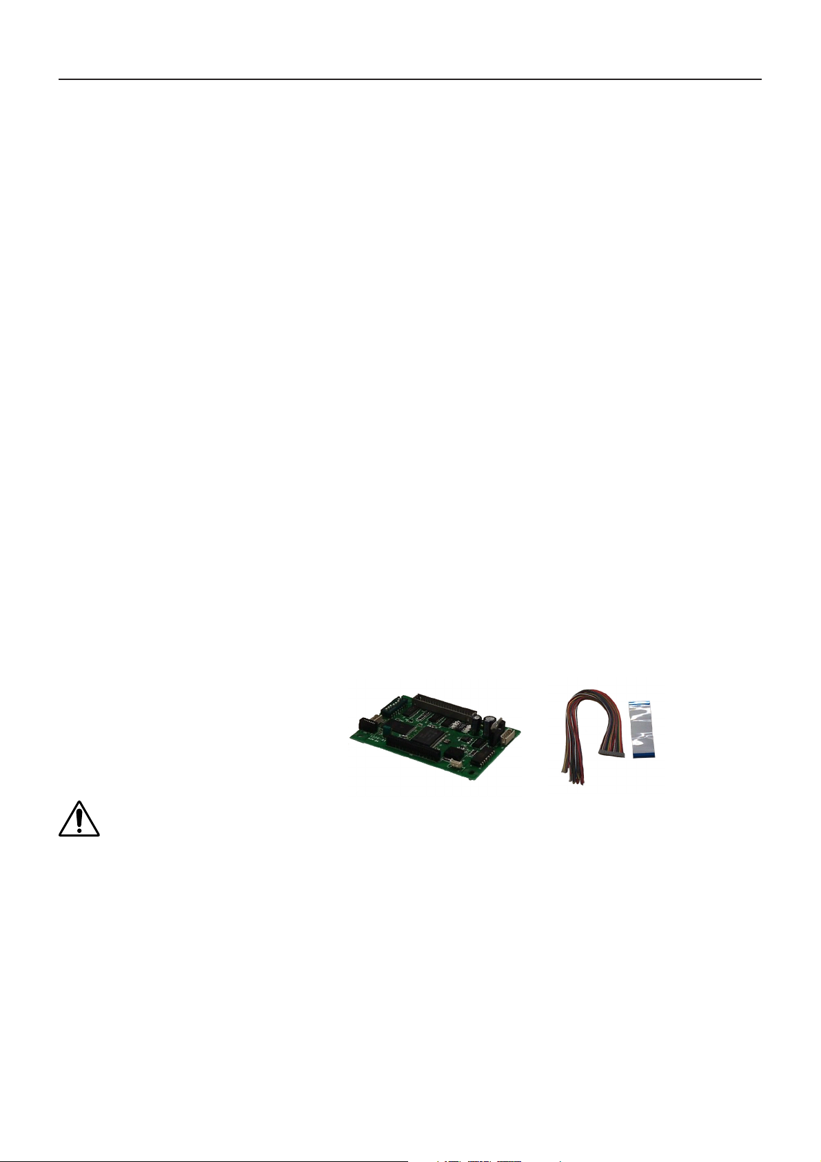
1.2 Before using
After unpacking, make sure that the following items are included in the package:
Control Board: .............................................................. 1
Interface Cable: .............................................................1 (cable length 300 mm)
Ribbon cable for print head interface: .......................... 1 (cable length 100 mm)
CAUTION:
• Whenever plugging or unplugging a cable, be sure to remove power from the control board.
• Never short connector pins to each other.
• Use the power supply, LED lights, and interface within their specified ratings.
• Install the control board on a flat, sturdy table.
• Do not install the control board near a heater or in a place exposed to direct sunlight.
• Do not use the control board in a high-temperature, high-humidity, or heavily contaminated environment.
• Do not use the control board in an environment where condensation may occur. If condensation should occur,
leave the power turned off until condensation evaporates completely.
1
2. BASIC SPECIFICATIONS
2.1 Model Classification
The control board models are classified by the following designation method:
BD2 - 122 0 U
Model Name
BD2-1220/1221 User’s Manual
Character Set
U : International model
Compatible printing mechanism:
0: LT-1220/1320
1: LT-1221/1321
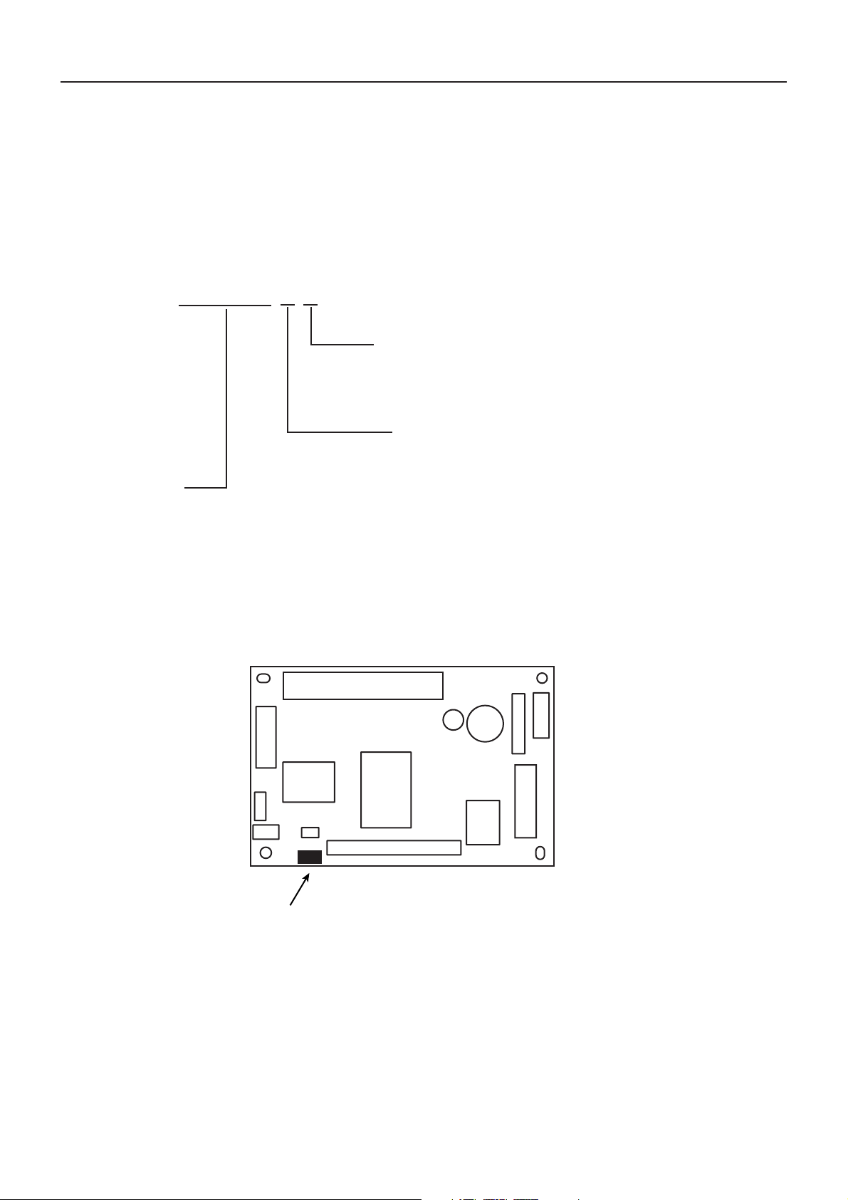
The control board has the following model identification:
Letter “U” and number “0” or “1” are stamped on the component side following the model number.
BD2122
Stamp location
2

2.2 Basic Specifications
BD2-1220/1221 User’s Manual
Model
Item
Print method
Paper width/printable
area width
Total number of dots
Dot density
Print speed
Paper feed span
Number of print
columns
Character size
Character type
Logo registration/print
Types of bar code
Line spacing
Interfacing
Input buffer
Sensors
Supply voltages
Current consumption
Thermal paper
Operating temperature
and humidity
Storage temperature and
humidity
Outside dimensions
Weight
BD2-122xU
Line thermal dot print method
LT-122x: Paper width: 58mm Printable area width: 54mm
LT-132x: Paper width: 80mm Printable area width: 72mm
LT-122x: 432 dots/lines
LT-132x: 576 dots/lines
8 dots/mm
MAX. 640 dot lines/sec
0.125mm
LT-122x: Font A: 36 columns Font B: 48 columns
LT-132x: Font A: 48 columns Font B: 64 columns
Font A: 1.25 × 3.00mm Font B: 0.88 × 3.00mm
Alphanumeric, International characters, symbols, Code 437, 850, 852,
857, 860, 863, 865, 866, Windows code, Katakana
Capable of registering user-defined characters and logos into flash
memory.
UPC-A/E, JAN (EAN) 13 columns/8 columns, ITF, CODABAR,
CODE39, CODE93, CODE128
4.23mm (1/6 inch) (Controllable with command)
Serial (RS-232C), Parallel (Centronics compliant)
4K bytes
Print head temperature, paper, head-up, and driving voltage sensors
Logic: 5V ±5% Approx. 200 mA (ANK slide printing)
Driver: 24V ±10% 0.7 A on average (For 12.5% of print area)
Print head: Approx. 5.2 A max. (for simultaneous 288-dot driving)
Approx. 0.52 A on average (For 12.5% of print area)
Motor: Approx. 0.4 A max. (Mean head resistance at 25°C and 640 pps)
Approx. 0.14 A on average
Thermal paper/thermal roll paper
Paper width: 58 mm (80mm) +0, –1mm
Paper thickness: 60 to 150 µm (Depending on mechanism)
5 to 40°C, 35 to 85%RH (No condensation)
–20 to 60°C, 10 to 90%RH (No condensation)
90mm (W) × 65mm (D) × 20mm (H) (See the outline drawings.)
Approx. 40g (Control Board only)
3

2.3 Print Paper Specifications
Use the recommended thermal papers listed below:
TF50KS-E2D (normal paper) from Nippon Paper
F230AA (normal paper) from Mitsubishi Paper or equivalent
*Paper thickness depends on the thermal head models.
* If an unspecified thermal paper is used, print tone may vary from the standard print tone.
*To preserve printed information for extended time period, carefully control temperature, humidity,
and other storage conditions.
* For the details of usable thermal papers, refer to the Specifications for each thermal print head.
* While you can use up to 150µm of paper thickness on some print heads, it is limited to 80 µm if the
auto cutter (ACS-220/230 Series) is used.
2.4 Thermal Print Head and Peripheral Devices
BD2-1220/1221 User’s Manual
The control board supports the following thermal print heads and peripheral devices:
(1)Thermal print head
80-mm paper: LT-1320/1321
58-mm paper: LT-1220/1221
(2)Auto cutter
ACS-230/220 Series Auto Cutter
(3)Paper Near End sensor (optional)
* For more detailed specifications for these devices, refer to each User’s Manual.
4

3. INTERCONNECTION
3.1 Interface Connector (CN1)
3.1.1 Pin Description
Pin No. Signal Name Input/Output Function
1, 2 Vdd — Logic power supply (+5 V)
3, 4 GND — Logic ground
5~10 Vp — Driver power supply (+24 V)
11~16 P-GND — Driver ground
17 nLF-SW Input LF switch input (paper feed)
18 nERROR Output ERROR LED output (direct diving)
19 nPEOUT Output PE LED output (direct driving)
20 DTR Output Serial interface DTR
21 TD Output Serial interface TD
22 RD Input Serial interface RD
23 DSR Input Serial interface DSR
24 DATA 0 Input Parallel interface DATA 0
25 DATA 1 Input Parallel interface DATA 1
26 DATA 2 Input Parallel interface DATA 2
27 DATA 3 Input Parallel interface DATA 3
28 DATA 4 Input Parallel interface DATA 4
29 DATA 5 Input Parallel interface DATA 5
30 DATA 6 Input Parallel interface DATA 6
31 DATA 7 Input Parallel interface DATA 7
32 nSTROBE Input Parallel interface STROBE
33 BUSY Output Parallel interface BUSY
34 nFAULT Output Parallel interface FAULT
35 SELECT Output Parallel interface SELECT
36 PE Output Parallel interface PE
37 nACK Output Parallel interface ACK
38 N. C — No Connection
39 N. C — No Connection
40 nRESET Input Parallel interface RESET
BD2-1220/1221 User’s Manual
Connector: 53313-4015 (Molex)
Accessory cable:
Connector shell: 51089-4005 (Molex)
Terminal: 50212 (Molex)
Cable: AWG26 (UL1007) or equivalent
Cable length: 300 mm (not terminated)
*Prefix “n” to signal names denotes active Low signals.
5

3.1.2 Example of Power Connections
* For the serial and parallel interface connections, see the sections dedicated to the respective
interface.
CN1
1, 2
3, 4
5 ~
10
Vdd +5V
GND GND
Vp +24V
+24V
BD2-1220/1221 User’s Manual
AC100 ~
240V
Regulated DC
power supply
P-GND GND
LF SW
ERROR LED
PEOUT LED
SW
+5V
5V supply line or
CN1-1 (2)
Supply GND or
CN1-3 (4)
CPU
Vdd
10KΩ
1000pF
330Ω
330Ω
Control Board
11 ~
16
17
18
19
CAUTION:
(1) The ERROR and PEOUT LED lights have a current limiting resistor of 330Ω each to limit driving current to 10 mA.
An LED with forward voltage drop under 2 V should thus be used for these lights. A driving current exceeding 10
mA could damage the control board electronics.
(2) The logic power supply (Vdd and GND) may have supply and return connections only to a single pin each.
However, the driver power supply (Vp and P-GND) must be connected to all the available pins in order to secure
the specified drive current capacity.
(3) As shown above, the LF-SW input connection is a circuit that uses a ceramic capacitor to prevent chattering. You
can adjust the switch if chattering is severe.
(4) The RESET input is pulled up to Vdd with an on-board 3.3KΩ resistor. Leave it at NC if it will not be used.
(5) The serial interface uses RS-232C driver and receiver. Be sure to use RS-232C compatible signal levels for this
interface.
(6) Unused terminals should be insulated to keep exposed cable leads from them.
6
3.2 Print Head Interface Connector (CN2)
3.2.1 Pin Description
BD2-1220/1221 User’s Manual
Pin No.
Signal Name
Input/Output Function
LT-122x LT-132x
1~4 Vp — Thermal head power supply
5 DO Input Serial print data input
6 CLK Output Data transfer clock
7 LAT Output Print data latch signal
8 N. C STB 2 — (Output) N.C. (Strobe 2)
9 STB 1 Output Strobe 1
10 TM — Thermistor
11~19 GND — GND
20 TM — Thermistor
21 Vdd — Thermal head driver power supply
22 STB 3 STB 4 Output Strobe 3 (4)
23 STB 2 STB 3 Output Strobe 2 (3)
24 D1 Output Serial print data output
25~28 Vp —
Connectors: CFF1128-0101 (SMK)
52045-2845 (Molex) or equivalent
* Note that the cable connector pin arrangement is in the reverse order to that on the control board.
The pin arrangement above is that on the control board.
* For the details of print head mechanisms, see the specifications for each model of print head.
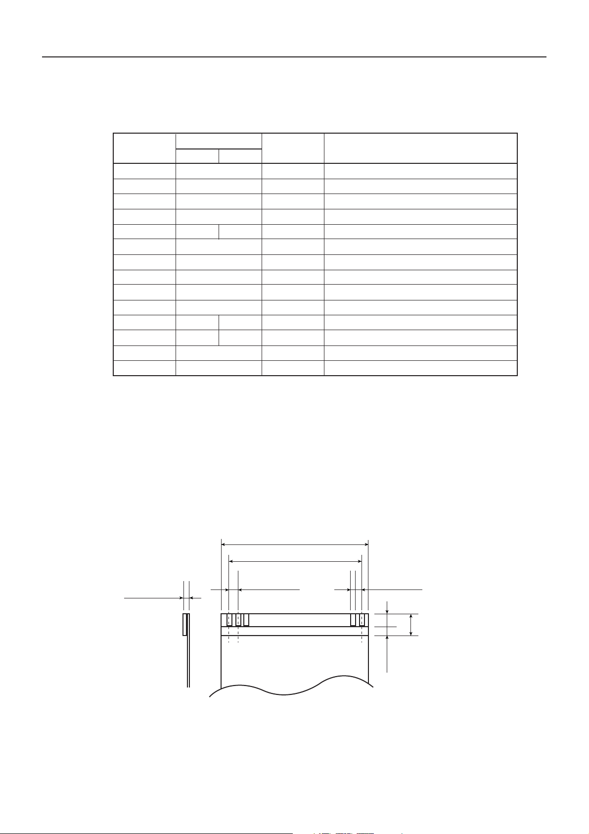
3.2.2 Compatible FFC Cable
0.3 ± 0.05
36.25 ± 0.1
33.75 ± 0.1
1.25 ± 0.05
Conductor side
0.8 ± 0.03
7
MIn. 4
Unit (mm)
Dimensions of
reinforcement plate
7
 Loading...