


Cisco Systems 2484-B8415-R1 Manual
Chapter 6 Installation
PRELIMINARY
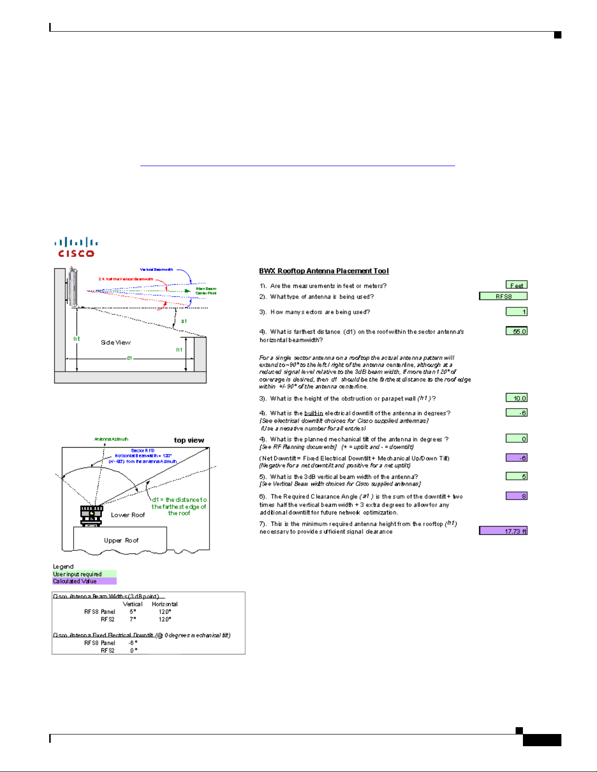
6.3.6 Rooftop Antenna Placement Tool
Reference: Rooftop Antenna Placement Tool
This is a picture of the worksheet in the Antenna Placement Tool for a quick visual identification
Figure 6-17); this appendix does not include the entire tool. Please use the electronic copy of the tool to
datafill the site information. This form can be found on the following LiveLink site:
https://tools.cisco.com/cws/livelink?func=ll&objid=4353291&objaction=browse
The Tool is updated periodically. If you are not sure that you have the latest version, please contact Cisco
Technical Services and request that the latest version of the tool be sent to you.
Figure 6-17 Rooftop Antenna Placement Tool
6.3.6 Rooftop Antenna Placement Tool
OL-19519-01
BWX 8415 Basestation Installation and Commissioning Guide
6-17
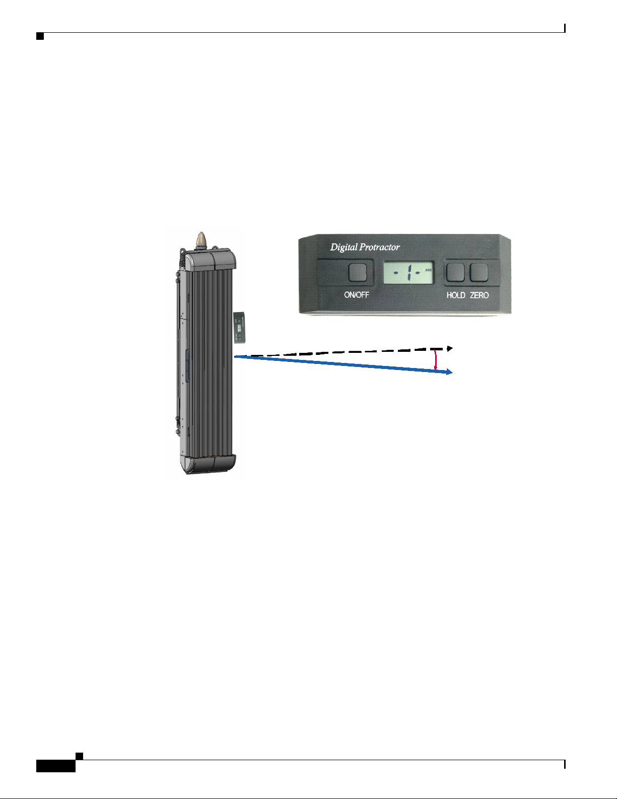
6.3.7 Set the Downtilt
6.3.7 Set the Downtilt
Based on coverage objectives determined by previous RF planning, the AU may need adjusting upward
or downward once mounted on the pole, tower, roof, building, or other structure. The panel antenna has
a -6° built-in electrical downtilt.
You will use an inclinometer to read the mounted position and to determine what adjustments, if any,
need to be made. For example, if the inclinometer reads +2° (uptilt) and you are mounting an AU, the
resulting beam has a –4° downtilt (
Figure 6-18 Downtilt Adjustment Example
Chapter 6 Installation
PRELIMINARY
Figure 6-18).
t
t
t
t
t
t
t
t
t
t
t
t
n
n
n
n
n
n
n
n
n
n
n
n
e
e
e
e
e
e
e
e
e
e
e
e
r
r
r
r
r
r
r
r
r
r
r
r
a
a
a
a
a
a
a
a
a
a
a
a
p
p
p
p
p
p
p
p
p
p
p
p
p
p
p
p
p
p
p
p
p
p
p
p
A
A
A
A
A
A
A
A
A
A
A
A
E
E
E
E
E
E
E
E
E
E
E
E
f
f
f
f
f
f
f
f
f
f
f
f
f
f
f
f
f
f
f
f
f
f
f
f
e
e
e
e
e
e
e
e
e
e
e
e
c
c
c
c
c
c
c
c
c
c
c
c
t
t
t
t
t
t
t
t
t
t
t
t
i
i
i
i
i
i
i
i
i
i
i
i
v
v
v
v
v
v
v
v
v
v
v
v
e
e
e
e
e
e
e
e
e
e
e
e
The inclinometer reads +1 ° (uptilt)
The inclinometer reads +1 ° (uptilt)
The panel antenna has a -6 ° built in
The panel antenna has a -6 ° built in
electrical downtilt
electrical downtilt
The resulting beam has a -5
The resulting beam has a -5
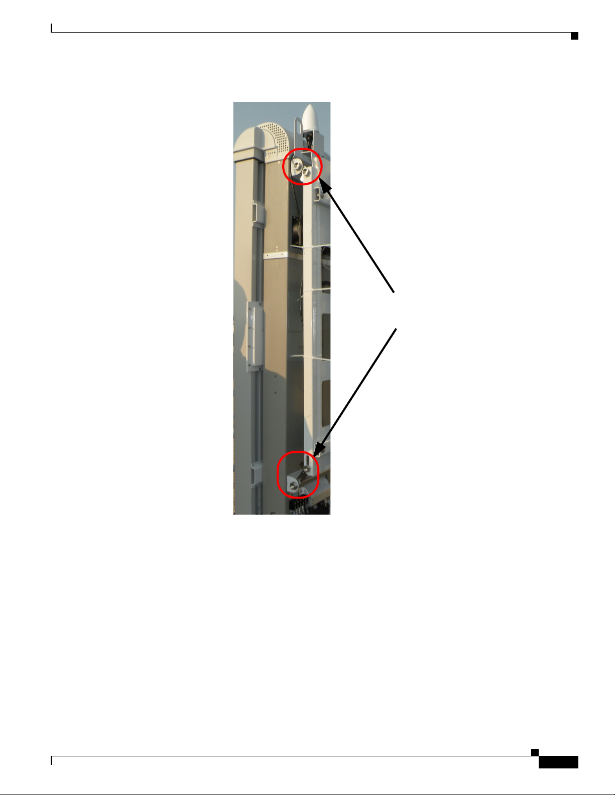
The downtilt can be adjusted per the assembly shown in Figure 6-19
°
°
°
°
°
°
°
°
°
°
°
°
1
1
1
1
1
1
1
1
1
1
1
1
+
+
+
+
+
+
+
+
+
+
+
+
Electr ical –6°
Electr ical –6°
Electr ical –6°
Electr ical –6°
Electr ical –6°
Electr ical –6°
Electr ical –6°
Electr ical –6°
Electr ical –6°
Electr ical –6°
Electr ical –6°
Electr ical –6°
–
–
–
–
–
–
–
–
–
–
–
–
°
°
°
°
°
°
°
°
°
°
°
°
5
5
5
5
5
5
5
5
5
5
5
5
° downtilt
° downtilt
6-18
BWX 8415 Basestation Installation and Commissioning Guide
OL-19519-01
Chapter 6 Installation
6.3.8 Antenna Orientation
PRELIMINARY
Figure 6-19 Downtilt Adjustment Assembly
Downtilt Adjustment
Bracket Bolts
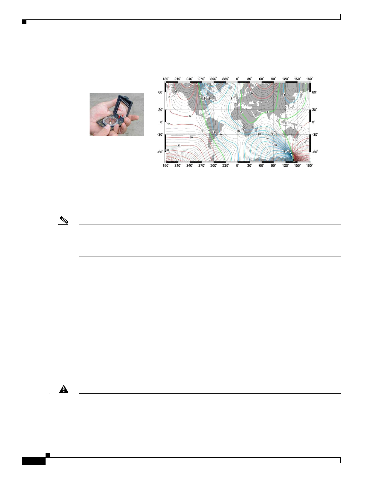
6.3.8 Antenna Orientation
The magnetic declination, which is the angular difference between observed magnetic north on a
compass and geographic (or “true”) north, shifts from year to year. Panel antennas must be oriented
appropriately as required by the RF plan.
Adjustments that will need to be made are based on the Magnetic Declination Chart (Figure 6-20), which
provides values to correct the compass reading and determine the true geographic East. Always check
for the latest chart information, which may be found at the following web address:
www.thecompassstore.com/decvar.html.
Since this is not the year 2000 any more, you will want to check this reference chart to learn how your
magnetic declination may have shifted since then. Notice that the map measures annual shifts in minutes.
Since it takes 60 minutes to equal 1 degree, if you notice that your location has a declination shift of 5
minutes per year, this means it will be another 12 years before your declination adjustment changes by
one whole degree.
OL-19519-01
BWX 8415 Basestation Installation and Commissioning Guide
6-19
6.4 Power and Ground Cabling
Figure 6-20 Magnetic Declination Chart – Example
PRELIMINARY
World Magnetic Declination Chart - Year 2000
World Magnetic Declination Chart - Year 2000
Use a compass to determine the magnetic East
Chapter 6 Installation
Unit:Degrees
Unit:Degrees
Use a Magnetic Declination chart to correct the compass reading
and determine the true geographic East
Note It is better to convert the “true” azimuth (which way the antenna should point in the horizontal plane) as
required by the RF Plan to the magnetic value that will be read on the compass before sending the
installer to the field. This way the installer will go by the reading on the compass, not having to worry
about magnetic declination corrections.
6.4 Power and Ground Cabling
6.4.1 Overview
The BS will operate at an input voltage of - 48 V DC, as measured at the input terminals to the BS.
General power and grounding information was covered in Chapter 5, “Pre-installation.” Please refer
there for information about power and ground cabling.
6.4.2 System Ground Cabling
6-20
The BS must be grounded prior to connecting power.
Warning
BWX 8415 Basestation Installation and Commissioning Guide
This equipment must be externally grounded using the supplied ground wire before power is applied.
Contact the appropriate electrical inspection authority or an electrician if you are uncertain that
suitable grounding is available.
Statement 366
OL-19519-01
Chapter 6 Installation
6.4.2 System Ground Cabling
PRELIMINARY
Warning
Warning
Note It is strongly recommended that no switch or disconnect device be installed in the ground cabling.
Read the installation instructions before connecting the system to the power source.
When installing or replacing the unit, the ground connection must always be made first and
disconnected last.
Statement 1046
Statement 1004
In all installations and when powering the BS, you must follow these instructions to properly ground the
BS:
Step 1 Strip the insulation as required for the grounding lug.
Step 2 Use the appropriate crimping tool to crimp the supplied 6-AWG grounding lug to the bare copper ground
wire.
Step 3 Apply heat shrink to the grounding lug.
Step 4 Open the electrical joint compound (supplied), and apply a liberal amount over the metal surface where
the grounding connectors are located.
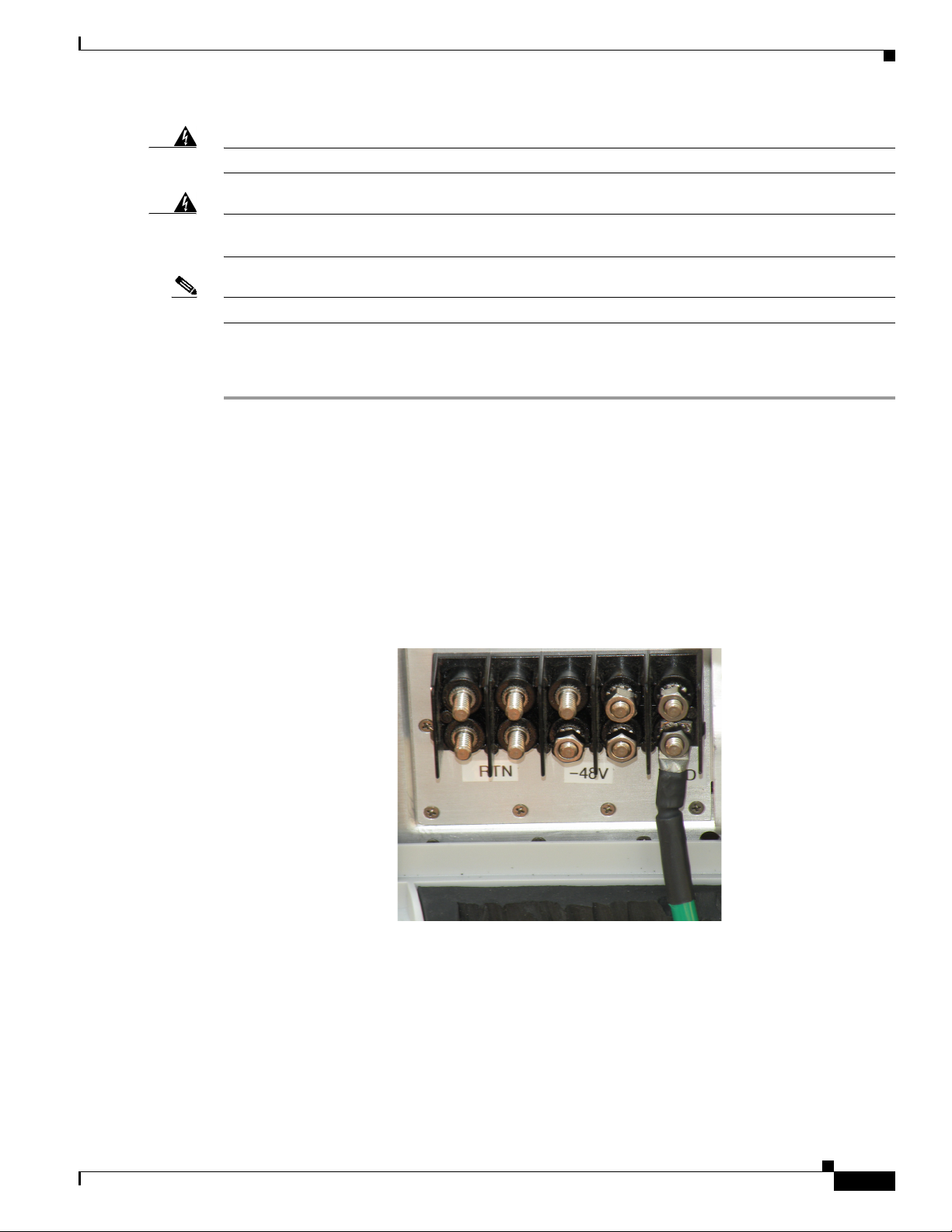
Step 5 Connect the ground cable to the BS ground using the supplied nuts with lock washers. Tighten the nuts
to 48 in-lbs. (5.4 Nm). Refer to
Figure 6-21.
Figure 6-21 Ground Cable Installed
Step 6 If necessary, strip the other end of the ground wire, and connect it to a reliable earth ground such as a
grounding rod or an appropriate grounding point on the pole/mast that is grounded.
OL-19519-01
BWX 8415 Basestation Installation and Commissioning Guide
6-21
 Loading...