


Cisco Systems 102104 Manual

Cisco Systems, Inc.
www.cisco.com
Cisco has more than 200 offices worldwide.
Addresses, phone numbers, and fax numbers
are listed on the Cisco website at
www.cisco.com/go/offices.
Cisco Aironet 1560 Series Outdoor Access
Point Hardware Installation Guide
First Published: August 30, 2016
Text Part Number:

THE SPECIFICATIONS AND INFORMATION REGARDING THE PRODUCTS IN THIS MANUAL ARE SUBJECT TO CHANGE WITHOUT NOTICE. ALL
STATEMENTS, INFORMATION, AND RECOMMENDATIONS IN THIS MANUAL ARE BELIEVED TO BE ACCURATE BUT ARE PRESENTED WITHOUT
WARRANTY OF ANY KIND, EXPRESS OR IMPLIED. USERS MUST TAKE FULL RESPONSIBILITY FOR THEIR APPLICATION OF ANY PRODUCTS.
THE SOFTWARE LICENSE AND LIMITED WARRANTY FOR THE ACCOMPANYING PRODUCT ARE SET FORTH IN THE INFORMATION PACKET THAT
SHIPPED WITH THE PRODUCT AND ARE INCORPORATED HEREIN BY THIS REFERENCE. IF YOU ARE UNABLE TO LOCATE THE SOFTWARE LICENSE
OR LIMITED WARRANTY, CONTACT YOUR CISCO REPRESENTATIVE FOR A COPY.
The following information is for FCC compliance of Class A devices: This equipment has been tested and found to comply with the limits for a Class A digital device, pursuant
to part 15 of the FCC rules. These limits are designed to provide reasonable protection against harmful interference when the equipment is operated in a commercial
environment. This equipment generates, uses, and can radiate radio-frequency energy and, if not installed and used in accordance with the instruction manual, may cause
harmful interference to radio communications. Operation of this equipment in a residential area is likely to cause harmful interference, in which case users will be required
to correct the interference at their own expense.
The following information is for FCC compliance of Class B devices: This equipment has been tested and found to comply with the limits for a Class B digital device, pursuant
to part 15 of the FCC rules. These limits are designed to provide reasonable protection against harmful interference in a residential installation. This equipment generates,
uses and can radiate radio frequency energy and, if not installed and used in accordance with the instructions, may cause harmful interference to radio communications.
However, there is no guarantee that interference will not occur in a particular installation. If the equipment causes interference to radio or television reception, which can be
determined by turning the equipment off and on, users are encouraged to try to correct the interference by using one or more of the following measures:
• Reorient or relocate the receiving antenna.
• Increase the separation between the equipment and receiver.
• Connect the equipment into an outlet on a circuit different from that to which the receiver is connected.
• Consult the dealer or an experienced radio/TV technician for help.
Modifications to this product not authorized by Cisco could void the FCC approval and negate your authority to operate the product.
The Cisco implementation of TCP header compression is an adaptation of a program developed by the University of California, Berkeley (UCB) as part of UCB’s public
domain version of the UNIX operating system. All rights reserved. Copyright © 1981, Regents of the University of California.
NOTWITHSTANDING ANY OTHER WARRANTY HEREIN, ALL DOCUMENT FILES AND SOFTWARE OF THESE SUPPLIERS ARE PROVIDED “AS IS” WITH
ALL FAULTS. CISCO AND THE ABOVE-NAMED SUPPLIERS DISCLAIM ALL WARRANTIES, EXPRESSED OR IMPLIED, INCLUDING, WITHOUT
LIMITATION, THOSE OF MERCHANTABILITY, FITNESS FOR A PARTICULAR PURPOSE AND NONINFRINGEMENT OR ARISING FROM A COURSE OF
DEALING, USAGE, OR TRADE PRACTICE.
IN NO EVENT SHALL CISCO OR ITS SUPPLIERS BE LIABLE FOR ANY INDIRECT, SPECIAL, CONSEQUENTIAL, OR INCIDENTAL DAMAGES, INCLUDING,
WITHOUT LIMITATION, LOST PROFITS OR LOSS OR DAMAGE TO DATA ARISING OUT OF THE USE OR INABILITY TO USE THIS MANUAL, EVEN IF CISCO
OR ITS SUPPLIERS HAVE BEEN ADVISED OF THE POSSIBILITY OF SUCH DAMAGES.
Cisco and the Cisco logo are trademarks or registered trademarks of Cisco and/or its affiliates in the U.S. and other countries. To view a list of Cisco trademarks, go to this
URL: www.cisco.com/go/trademarks. Third-party trademarks mentioned are the property of their respective owners. The use of the word partner does not imply a partnership
relationship between Cisco and any other company. (1110R)
Any Internet Protocol (IP) addresses and phone numbers used in this document are not intended to be actual addresses and phone numbers. Any examples, command display
output, network topology diagrams, and other figures included in the document are shown for illustrative purposes only. Any use of actual IP addresses or phone numbers in
illustrative content is unintentional and coincidental.
© 2016 Cisco Systems, Inc. All rights reserved.

iii
Cisco Aironet 1560 Series Outdoor Access Point Hardware Installation Guide
CONTENTS
Preface vii
Objectives vii
Audience vii
Organization vii
Conventions viii
Related Documents xiv
Finding the Product Serial Number xiv
Obtaining Documentation, Support, and Security Guidelines xvi
CHAPTER
1 Overview 1-1
About the 1560 Access Point 1-1
Hardware Models 1-2
Regulatory Domains 1-2
Hardware Features 1-3
Connectors 1-3
1562I/1562D Connectors 1-4
1562I/E/D Connectors 1-7
External Antenna Port Locations on AP1562E 1-9
Radio Operation 1-9
AP1562I (Internal Antenna) 1-10
AP1562E (External Antenna) 1-10
Multiple Power Sources 1-10
Power injectors 1-11
Ethernet (PoE) Ports 1-12
Optional Hardware 1-12
Network Deployment Examples 1-13
Wireless Backhaul 1-13
Point-to-Point Bridging 1-13
Point-to-Multipoint Bridging 1-14
Point-to-Multipoint Mesh Network 1-16
Layer 3 Network Operation 1-17

Contents
iv
Cisco Aironet 1560 Series Outdoor Access Point Hardware Installation Guide
CHAPTER
2 Installing the Access Point 2-1
Unpacking the Access Point 2-2
Package Contents 2-2
Tools and Hardware 2-2
Optional Tools and Hardware 2-2
Optional Tools and Hardware That You Supply 2-3
Warnings 2-3
Safety Information 2-4
FCC Safety Compliance Statement 2-4
Safety Precautions 2-4
Avoiding Damage to Radios in a Testing Environment 2-6
Installation Guidelines 2-7
Site Surveys 2-7
Before Beginning the Installation 2-8
Becoming Familiar with Access Point Installation Components 2-8
Mounting the Access Point 2-11
AP Mounting Options 2-11
Access Point Mounting Orientation 2-11
Wall Mounting the Access Point with AIR-ACC1530-PMK1= Mounting Kit 2-12
Wall Mounting the Access Point with AIR-ACC1560-PMK1= Mounting Kit 2-15
Pole Mounting the Access Point with the AIR-ACC1530-PMK2= Kit 2-18
Pole Mounting the Access Point with the AIR-ACC1560-PMK2= Kit 2-20
Wall Mounting the Access Point with the Pivoting Mounting Kit 2-22
Pole Mounting the Access Point with the Pivoting Mounting Kit 2-25
Horizontally Mounting the Access Point with Optional Horizontal Mount Plate 2-28
Installing AP Cover or Solar Shield (AIR-ACC1560-CVR=) 2-32
Installing Antennas 2-33
Non-Cisco Antennas 2-33
Safety Precautions when Installing Antennas 2-34
Antenna Configurations 2-34
Integrated Antenna Option 2-34
External Antenna Mounting Configurations 2-35
Using a Mounting Bracket for External Directional Antennas 2-43
Antenna N-Type Connector Locations 2-44
Installing a Lightning Arrestor 2-44
Installation Considerations 2-44
Installation Notes 2-45
Installing the Lightning Arrestor Outdoors 2-45

Contents
v
Cisco Aironet 1560 Series Outdoor Access Point Hardware Installation Guide
Cable for the Lightning Arrestor 2-46
Grounding the Access Point 2-46
Powering the Access Point 2-47
Connecting a 1560 Series Power Injector 2-48
Connecting an Ethernet Cable to the Access Point 2-49
Connecting a DC Power Cable to the Access Point 2-52
Connecting Streetlight AC Power 2-56
Connecting a Fiber-optic Cable to the AP 2-58
Configuring the Access Point 2-62
What to Do Next 2-63
CHAPTER
3 Troubleshooting 3-1
Guidelines for Using the Access Points 3-2
Important Notes 3-2
Convergence Delays 3-2
Bridge Loop 3-3
Controller DHCP Server 3-3
MAP Data Traffic 3-3
Controller MAC Filter List 3-3
Using DHCP Option 43 3-3
Monitoring the Access Point LEDs 3-4
Verifying Controller Association 3-6
Changing the Bridge Group Name 3-7
Accessing the Console Port and the Reset Button 3-7
Resetting the Access Point 3-9
APPENDIX
A Translated Safety Warnings A-1
APPENDIX
B Declarations of Conformity and Regulatory Information B-1
Manufacturers Federal Communication Commission Declaration of Conformity Statement B-2
Requirements of operator to register the RLAN device operating Outdoors in the 5150 -5250 MHz
band and addressing possible interference issues in this band
B-3
Industry Canada B-3
Canadian Compliance Statement B-3
Declaration of Conformity for RF Exposure B-5
European Community, Switzerland, Norway, Iceland, and Liechtenstein B-6
Declaration of Conformity with regard to the R&TTE Directive 1999/5/EC & Medical Directive
93/42/EEC
B-6

Contents
vi
Cisco Aironet 1560 Series Outdoor Access Point Hardware Installation Guide
Declaration of Conformity for RF Exposure B-9
United States B-9
Canada B-9
European Union B-9
Australia B-9
Guidelines for Operating Cisco Aironet Access Points in Japan B-10
Japanese Translation B-10
English Translation B-10
VCCI Statement for Japan B-11
Administrative Rules for Cisco Aironet Access Points in Taiwan B-11
Chinese Translation B-11
English Translation B-12
Chinese Translation B-12
English Translation B-12
Statement 371—Power Cable and AC Adapter B-13
English Translation B-13
EU Declaration of Conformity B-13
Operation of Cisco Aironet Access Points in Brazil B-13
Access Point Models B-13
Regulatory Information B-14
Portuguese Translation B-14
English Translation B-14
APPENDIX
C Channels and Power Levels C-1
APPENDIX
D Access Point Data Sheet D-1
APPENDIX
E Access Point Pinouts E-1
APPENDIX
F Configuring DHCP Option 43 F-1
vii
Cisco Aironet 1560 Series Outdoor Access Point Hardware Installation Guide
Preface
This section describes the objectives, audience, organization, and conventions of the Cisco Aironet 1560
Series Outdoor Access Point Hardware Installation Guide.
Objectives
This publication explains the steps for installing the Cisco Aironet 1560 Series Outdoor Access Points
(called the access point in this document).
Audience
This publication is for the person installing and configuring an access point for the first time. The
installer should be familiar with network structures, terms, and concepts.
Warning
Only trained and qualified personnel should be allowed to install, replace, or service this equipment.
Statement 1030
Warning
This equipment must be installed in restricted access locations in Norway, Finland, and Sweden. Only
trained and qualified personnel are allowed to install, replace, or service this equipment as
instructed in this installation guide.
Organization
This guide contains the following sections:
Chapter Title Description
Chapter 1 Overview Describes the major components and features
of the access point.
Chapter 2 Installing the Access Point Provides warnings, safety information, and
mounting information you need to install your
access point.

viii
Cisco Aironet 1560 Series Outdoor Access Point Hardware Installation Guide
Conventions
This publication uses the following conventions:
Notes use the following conventions:
Chapter 3 Troubleshooting Provides basic troubleshooting procedures for
the access point.
Appendix A Translated Safety Warnings Indicates how to access the document that
provides translations of the safety warnings
that appear in this publication.
Appendix B Declarations of Conformity
and Regulatory Information
Describes the regulatory conventions to which
the access point conforms and provides
guidelines for operating access points in Japan.
Appendix C Channels and Power Levels Indicates how to access the document that lists
the access point radio channels and the
maximum power levels supported by the world
regulatory domains.
Appendix D Access Point Data Sheet Lists technical specifications for the access
point.
Appendix E Access Point Pinouts Describes the connector pinouts for the access
point.
Appendix F Configuring DHCP Option
43
Describes the procedure to configure DHCP
Option 43.
Chapter Title Description
Convention Description
boldface font Commands, command options, and keywords are
in boldface.
italic font Arguments for which you supply values are in
italics.
[ ] Elements in square brackets are optional.
screen font
Terminal sessions and information the system
displays are in screen font.
boldface screen font
Information you must enter is in boldface screen
font.
italic screen font
Arguments for which you supply values are in
italic screen font.
^ The symbol ^ represents the key labeled Control.
For example, the key combination ^D in a screen
display means hold down the Control key while
you press the D key.
< > Nonprinting characters, such as passwords, are in
angle brackets.

ix
Cisco Aironet 1560 Series Outdoor Access Point Hardware Installation Guide
Note Means reader take note. Notes contain helpful suggestions or references to materials not contained in
this manual.
Cautions use the following conventions:
Caution Means reader be careful. In this situation, you might do something that could result in equipment
damage or loss of data.
Warnings use the following conventions:
Warning
IMPORTANT SAFETY INSTRUCTIONS
This warning symbol means danger. You are in a situation that could cause bodily injury. Before you
work on any equipment, be aware of the hazards involved with electrical circuitry and be familiar
with standard practices for preventing accidents. Use the statement number provided at the end of
each warning to locate its translation in the translated safety warnings that accompanied this
device.
Statement 1071
SAVE THESE INSTRUCTIONS
Waarschuwing
BELANGRIJKE VEILIGHEIDSINSTRUCTIES
Dit waarschuwingssymbool betekent gevaar. U verkeert in een situatie die lichamelijk letsel kan
veroorzaken. Voordat u aan enige apparatuur gaat werken, dient u zich bewust te zijn van de bij
elektrische schakelingen betrokken risico's en dient u op de hoogte te zijn van de standaard
praktijken om ongelukken te voorkomen. Gebruik het nummer van de verklaring onderaan de
waarschuwing als u een vertaling van de waarschuwing die bij het apparaat wordt geleverd, wilt
raadplegen.
BEWAAR DEZE INSTRUCTIES
Varoitus
TÄRKEITÄ TURVALLISUUSOHJEITA
Tämä varoitusmerkki merkitsee vaaraa. Tilanne voi aiheuttaa ruumiillisia vammoja. Ennen kuin
käsittelet laitteistoa, huomioi sähköpiirien käsittelemiseen liittyvät riskit ja tutustu
onnettomuuksien yleisiin ehkäisytapoihin. Turvallisuusvaroitusten käännökset löytyvät laitteen
mukana toimitettujen käännettyjen turvallisuusvaroitusten joukosta varoitusten lopussa näkyvien
lausuntonumeroiden avulla.
SÄILYTÄ NÄMÄ OHJEET

x
Cisco Aironet 1560 Series Outdoor Access Point Hardware Installation Guide
Attention
IMPORTANTES INFORMATIONS DE SÉCURITÉ
Ce symbole d'avertissement indique un danger. Vous vous trouvez dans une situation pouvant
entraîner des blessures ou des dommages corporels. Avant de travailler sur un équipement, soyez
conscient des dangers liés aux circuits électriques et familiarisez-vous avec les procédures
couramment utilisées pour éviter les accidents. Pour prendre connaissance des traductions des
avertissements figurant dans les consignes de sécurité traduites qui accompagnent cet appareil,
référez-vous au numéro de l'instruction situé à la fin de chaque avertissement.
CONSERVEZ CES INFORMATIONS
Warnung
WICHTIGE SICHERHEITSHINWEISE
Dieses Warnsymbol bedeutet Gefahr. Sie befinden sich in einer Situation, die zu Verletzungen führen
kann. Machen Sie sich vor der Arbeit mit Geräten mit den Gefahren elektrischer Schaltungen und
den üblichen Verfahren zur Vorbeugung vor Unfällen vertraut. Suchen Sie mit der am Ende jeder
Warnung angegebenen Anweisungsnummer nach der jeweiligen Übersetzung in den übersetzten
Sicherheitshinweisen, die zusammen mit diesem Gerät ausgeliefert wurden.
BEWAHREN SIE DIESE HINWEISE GUT AUF.
Avvertenza
IMPORTANTI ISTRUZIONI SULLA SICUREZZA
Questo simbolo di avvertenza indica un pericolo. La situazione potrebbe causare infortuni alle
persone. Prima di intervenire su qualsiasi apparecchiatura, occorre essere al corrente dei pericoli
relativi ai circuiti elettrici e conoscere le procedure standard per la prevenzione di incidenti.
Utilizzare il numero di istruzione presente alla fine di ciascuna avvertenza per individuare le
traduzioni delle avvertenze riportate in questo documento.
CONSERVARE QUESTE ISTRUZIONI
Advarsel
VIKTIGE SIKKERHETSINSTRUKSJONER
Dette advarselssymbolet betyr fare. Du er i en situasjon som kan føre til skade på person. Før du
begynner å arbeide med noe av utstyret, må du være oppmerksom på farene forbundet med
elektriske kretser, og kjenne til standardprosedyrer for å forhindre ulykker. Bruk nummeret i slutten
av hver advarsel for å finne oversettelsen i de oversatte sikkerhetsadvarslene som fulgte med denne
enheten.
TA VARE PÅ DISSE INSTRUKSJONENE
Aviso
INSTRUÇÕES IMPORTANTES DE SEGURANÇA
Este símbolo de aviso significa perigo. Você está em uma situação que poderá ser causadora de
lesões corporais. Antes de iniciar a utilização de qualquer equipamento, tenha conhecimento dos
perigos envolvidos no manuseio de circuitos elétricos e familiarize-se com as práticas habituais de
prevenção de acidentes. Utilize o número da instrução fornecido ao final de cada aviso para
localizar sua tradução nos avisos de segurança traduzidos que acompanham este dispositivo.
GUARDE ESTAS INSTRUÇÕES
xi
Cisco Aironet 1560 Series Outdoor Access Point Hardware Installation Guide
¡Advertencia!
INSTRUCCIONES IMPORTANTES DE SEGURIDAD
Este símbolo de aviso indica peligro. Existe riesgo para su integridad física. Antes de manipular
cualquier equipo, considere los riesgos de la corriente eléctrica y familiarícese con los
procedimientos estándar de prevención de accidentes. Al final de cada advertencia encontrará el
número que le ayudará a encontrar el texto traducido en el apartado de traducciones que acompaña
a este dispositivo.
GUARDE ESTAS INSTRUCCIONES
Varning!
VIKTIGA SÄKERHETSANVISNINGAR
Denna varningssignal signalerar fara. Du befinner dig i en situation som kan leda till personskada.
Innan du utför arbete på någon utrustning måste du vara medveten om farorna med elkretsar och
känna till vanliga förfaranden för att förebygga olyckor. Använd det nummer som finns i slutet av
varje varning för att hitta dess översättning i de översatta säkerhetsvarningar som medföljer denna
anordning.
SPARA DESSA ANVISNINGAR
Figyelem
xii
Cisco Aironet 1560 Series Outdoor Access Point Hardware Installation Guide
Aviso
INSTRUÇÕES IMPORTANTES DE SEGURANÇA
Este símbolo de aviso significa perigo. Você se encontra em uma situação em que há risco de lesões
corporais. Antes de trabalhar com qualquer equipamento, esteja ciente dos riscos que envolvem os
circuitos elétricos e familiarize-se com as práticas padrão de prevenção de acidentes. Use o
número da declaração fornecido ao final de cada aviso para localizar sua tradução nos avisos de
segurança traduzidos que acompanham o dispositivo.
GUARDE ESTAS INSTRUÇÕES
Advarsel
VIGTIGE SIKKERHEDSANVISNINGER
Dette advarselssymbol betyder fare. Du befinder dig i en situation med risiko for
legemesbeskadigelse. Før du begynder arbejde på udstyr, skal du være opmærksom på de
involverede risici, der er ved elektriske kredsløb, og du skal sætte dig ind i standardprocedurer til
undgåelse af ulykker. Brug erklæringsnummeret efter hver advarsel for at finde oversættelsen i de
oversatte advarsler, der fulgte med denne enhed.
GEM DISSE ANVISNINGER
xiii
Cisco Aironet 1560 Series Outdoor Access Point Hardware Installation Guide
xiv
Cisco Aironet 1560 Series Outdoor Access Point Hardware Installation Guide
Related Documents
These documents provide complete information about the access point:
• Release Notes for Cisco Wireless LAN Controllers and Lightweight Access Points
• Quick Start Guide: Cisco Aironet 1560 Series Outdoor Access Points
• Cisco Wireless LAN Controller Configuration Guide
Click this link to browse to the Cisco Wireless documentation home page:
http://www.cisco.com/en/US/products/hw/wireless/index.html
To browse to the access point documentation, click Cisco Aironet 1560 Series listed under “Outdoor
Wireless.” The documentation can be accessed from the Support box.
To browse to the Cisco Wireless LAN Controller documentation, click Standalone Controllers listed
under “Wireless LAN Controllers.” The documentation can be accessed from the Support box.
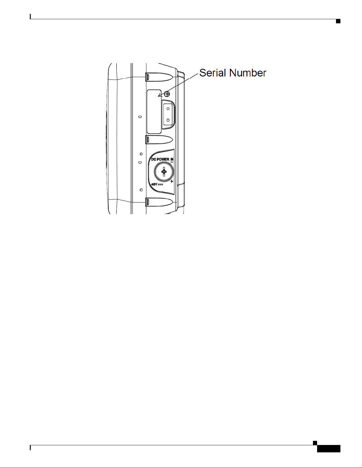
Finding the Product Serial Number
The access point serial number is on the side of the access point (refer to Figure 1).
xv
Cisco Aironet 1560 Series Outdoor Access Point Hardware Installation Guide
Figure 1 Location of Serial Number Label on the Left of the AP
The access point serial number label contains the following information:
• Model number, such as AIR-AP1562E-x-K9.
• Serial number, such as WCN0636279B (11 alphanumeric digits).
• Access point MAC address, for example 68BDABF54600 (12 hexadecimal digits). It is located
under the serial number.
You need your product serial number when requesting support from the Cisco Technical Assistance
Center.

xvi
Cisco Aironet 1560 Series Outdoor Access Point Hardware Installation Guide
Obtaining Documentation, Support, and Security Guidelines
For information on obtaining documentation and support, providing documentation feedback, security
guidelines, and recommended aliases and general Cisco documents, see the monthly What’s New in
Cisco Product Documentation, which also lists all new and revised Cisco technical documentation, at:
http://www.cisco.com/en/US/docs/general/whatsnew/whatsnew.html
To view all new wireless documentation, click on Wireless.

CHA P T ER
1-1
Cisco Aironet 1560 Series Outdoor Access Point Hardware Installation Guide
1
Overview
The Cisco Aironet 1560 Series Outdoor Access Point (hereafter called the access point or AP) is a
wireless outdoor access point which is designed for use in a variety of network configurations. The
access point supports wireless client access, point-to-point bridging, point-to-multipoint bridging, and
point-to-multipoint mesh wireless connectivity.
About the 1560 Access Point
The 1560 access point supports two radios (2.4-GHz and 5-GHz) and provides client access using the
unlicensed RF Wi-Fi spectrum. The radios have 802.11ac Wave 2 capability.
The 5 GHz radios have 802.11ac Wave 2 capability. The 2.4 GHz or 5 GHz radio can be used for client
access or can be used for both client access and backhaul traffic. Depending on the model, the access
point can support up to 1.3 Gbps data rates. For more information, see Appendix D, “Access Point Data
Sheet”.
The access point is a standalone unit that can be wall, pole or tower mounted. The access point can also
operate as a relay node for other access points not directly connected to a wired network. Intelligent
wireless routing is provided by the patented Adaptive Wireless Path Protocol (AWPP). This enables each
access point to identify its neighbors and intelligently choose the optimal path to the wired network by
calculating the cost of each path in terms of signal strength and the number of hops required to get to a
controller.
The access point can be configured, monitored, and operated through a Cisco wireless LAN controller
(hereafter called a controller) as described in the Cisco Wireless LAN Controller Configuration Guide.
The Cisco Wireless Mesh Access Points, Design and Deployment Guide, describes how to plan and
initially configure the Cisco mesh network, which supports wireless point-to-point, point-to-multipoint,
and mesh deployments. The controllers use a browser-based management system, a command-line
interface (CLI), or the Cisco Prime Infrastructure (PI) network management system to manage the
controller and the associated access points. The access point supports hardware-based advanced
encryption standard (AES) encryption between wireless nodes to provide end-to-end security. The
access point can also be deployed in an autonomous mode and be configured via the CLI.
This chapter provides information on the following topics:
• Hardware Models, page 1-2
• Hardware Features, page 1-3
• Network Deployment Examples, page 1-13

1-2
Cisco Aironet 1560 Series Outdoor Access Point Hardware Installation Guide
Chapter 1 Overview
Hardware Models
Hardware Models
The model numbers (or part numbers) and configuration for the Cisco Aironet 1560 Outdoor Access
Points are described in Tab l e 1-1.
For a detailed description of the declarations of conformity and regulatory information for the 1560
access points refer to Appendix B, “Declarations of Conformity and Regulatory Information.”
Regulatory Domains
The “-x” in the 1560 model numbers represent the domain. For example, in AIR-AP1562I-x-K9, the -x
represents a regulatory domain for a specific country. For specific regulatory domains supported by each
1560 access point model, refer to the Wireless LAN Compliance Status at the following URL:
http://www.cisco.com/go/aironet/compliance
Table 1-1 1560 Access Point Model Numbers and Descriptions
Model (or part number) Configuration
AIR-AP1562I-x-K9 The AP 1562I has integrated omni antennas and
contains a 2.4 GHz and 5 GHz radio with an
option to configure in centralized, Flexconnect, or
mesh mode.
This is a stand alone unit that can be wall, pole or
tower mounted. It can also operate as a relay node
for other access points that are not directly
connected to a wired network.
AIR-AP1562E-x-K9 The AP 1562E has 4 external antenna ports and
contains a 2.4 GHz and 5 GHz radio with an
option to configure in centralized, Flexconnect, or
mesh mode.
This is a stand alone unit that can be wall, pole or
tower mounted. It can also operate as a relay node
for other access points that are not directly
connected to a wired network.
AIR-AP1562D-x-K9 The AP 1562 has integrated directional antennas
and contains a 2.4 GHz and 5 GHz radio with an
option to configure in centralized, Flexconnect, or
mesh mode.
This is a stand alone unit that can be wall, pole or
tower mounted. It can also operate as a relay node
for other access points that are not directly
connected to a wired network.

1-3
Cisco Aironet 1560 Series Outdoor Access Point Hardware Installation Guide
Chapter 1 Overview
Hardware Features
Hardware Features
This section describes the hardware features of the 1560 access point models. The following hardware
features are described in this section:
• Connectors, page 1-3
• External Antenna Port Locations on AP1562E, page 1-9
• Multiple Power Sources, page 1-10
• Ethernet (PoE) Ports, page 1-12
• Optional Hardware, page 1-12
Connectors
Figure 1-4 and Figure 1-5 show the access point connectors for all models. Figure 1-1 shows the bottom
connectors for internal antenna model, and Figure 1-2 and Figure 1-3 show the external antenna Type-N
connectors.
Note The illustrations in this document show all available connections for the access point. Unused
connections are capped with a connector plug to ensure the watertight integrity of the access point.
Liquid-tight adapters are provided for connector openings, which can be installed before or after
deploying the access point.
1-4
Cisco Aironet 1560 Series Outdoor Access Point Hardware Installation Guide
Chapter 1 Overview
Hardware Features
1562I/1562D Connectors
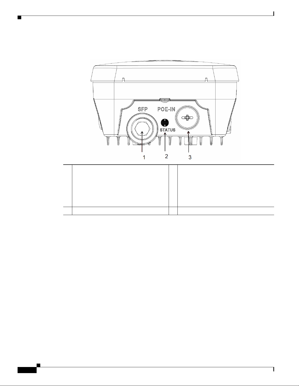
Figure 1-1 Access Point Models AP1562I and AP1562D Bottom Connectors
1 SFP port
If the port is not being used, then do not
remove the covering plug. Otherwise, it may
lead to water leaking into the access point.
3 Gigabit Ethernet and PoE-In port
If the port is not in use, then the covering plug
must be tightened to 12.5 lbf-in torque.
Otherwise, it may lead to water leaking into
the access point.
2 Status LED
1-5
Cisco Aironet 1560 Series Outdoor Access Point Hardware Installation Guide
Chapter 1 Overview
Hardware Features
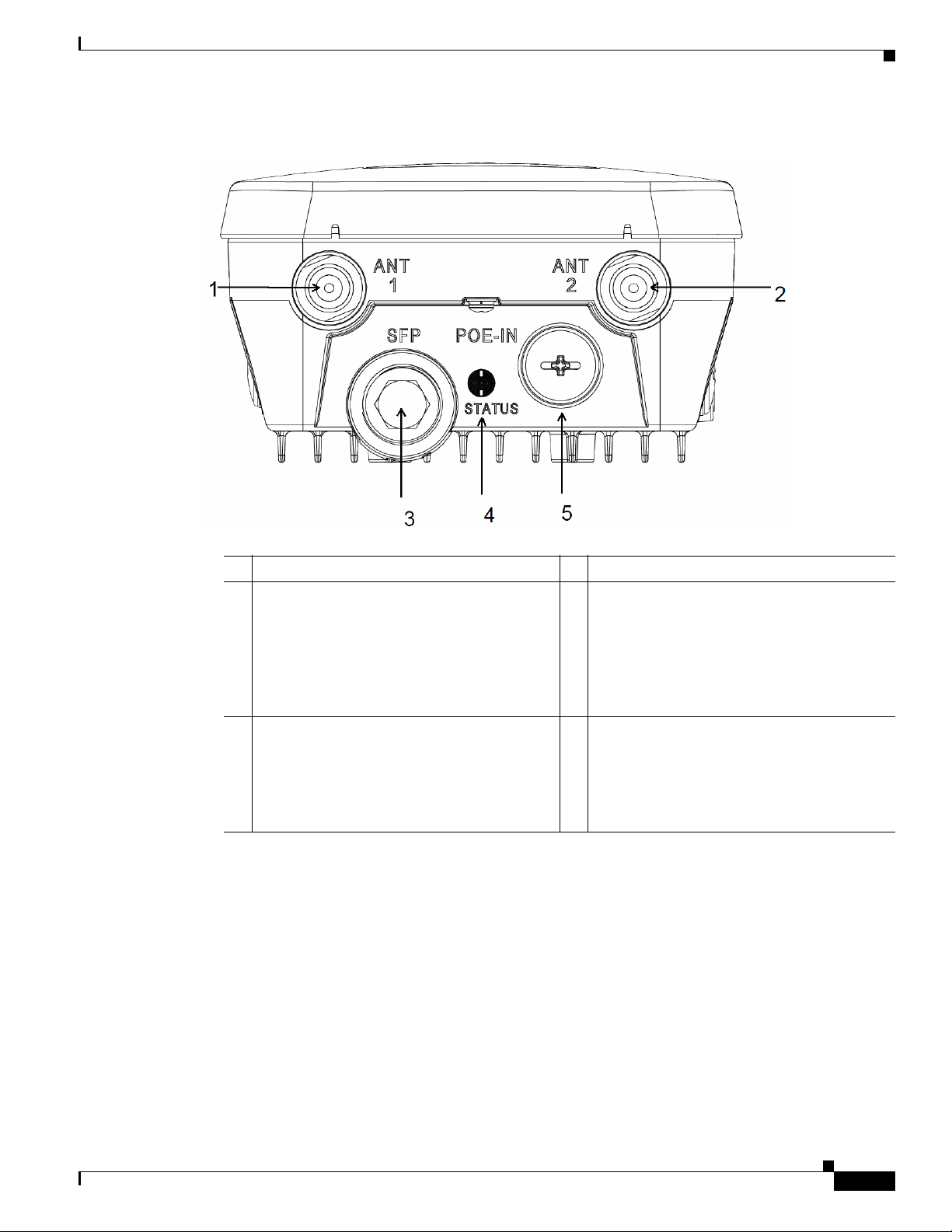
Figure 1-2 Access Point Model AP1562E Bottom Connectors
1 Antenna 1 port 4 Status LED
2 Antenna 2 port 5 Gigabit Ethernet and PoE-In port
If the port is not in use, then the covering plug
must be tightened to 12.5 lbf-in torque.
Otherwise, it may lead to water leaking into
the access point.
3 SFP port
If the port is not being used, then do not
remove the covering plug. Otherwise, it may
lead to water leaking into the access point.
1-6
Cisco Aironet 1560 Series Outdoor Access Point Hardware Installation Guide
Chapter 1 Overview
Hardware Features
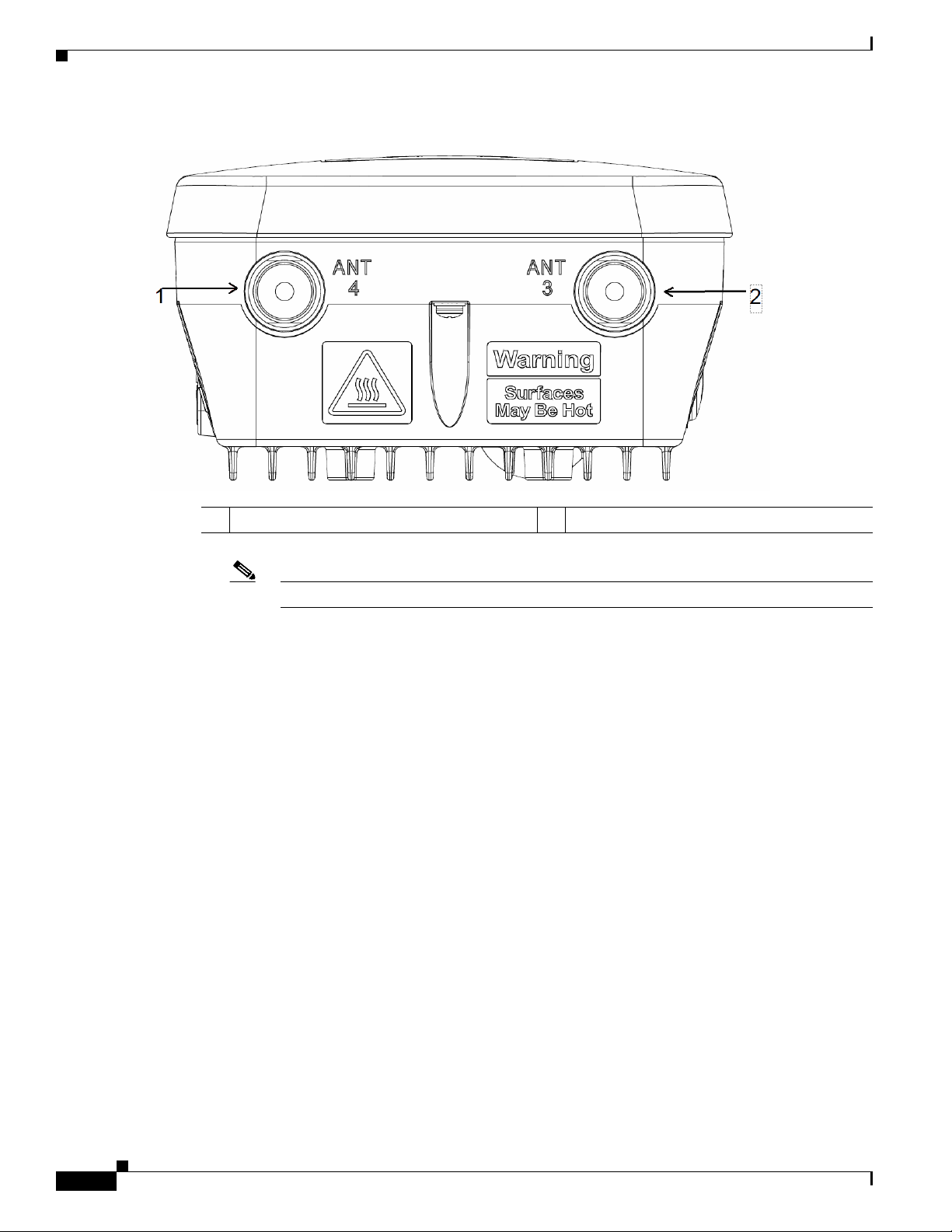
Figure 1-3 Access Point Model AP1562E Top Connectors
Note The AP1562I and AP1562D models do not have any top connectors.
1 Antenna port 4 2 Antenna port 3
1-7
Cisco Aironet 1560 Series Outdoor Access Point Hardware Installation Guide
Chapter 1 Overview
Hardware Features
1562I/E/D Connectors
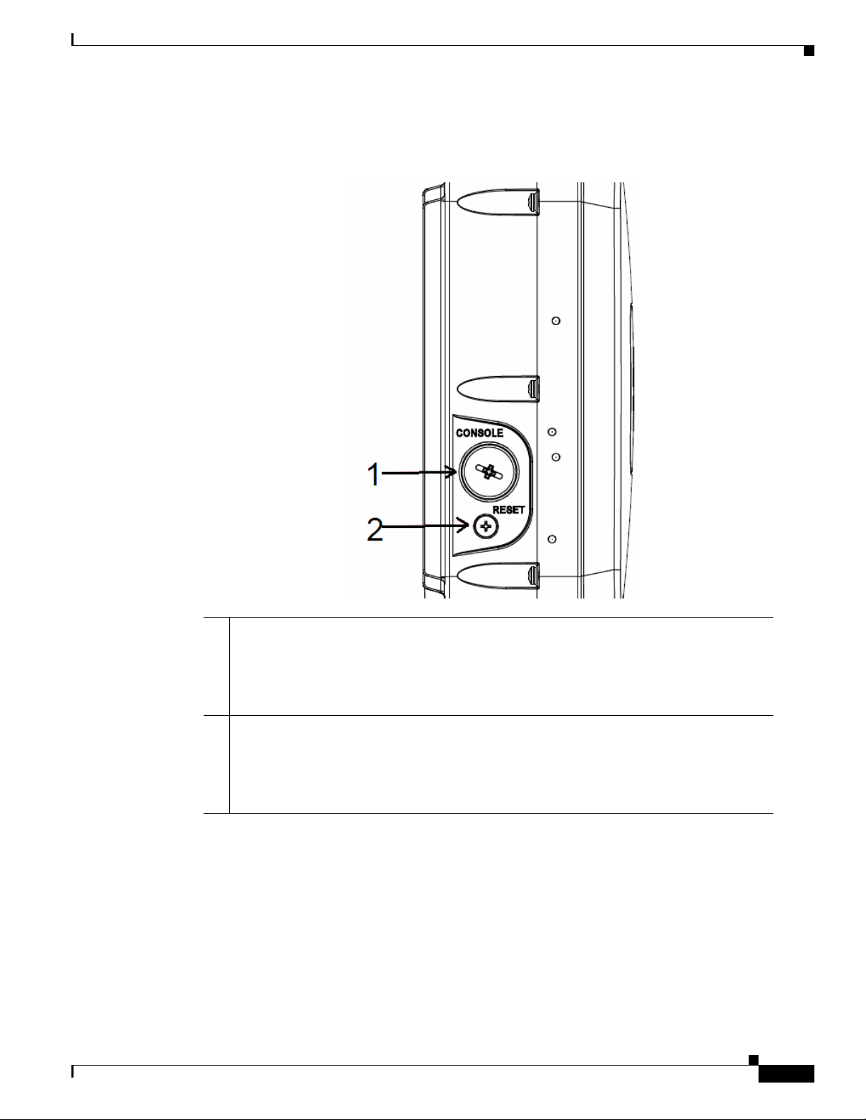
Figure 1-4 Right Side Connectors on all models
1 Console port.
The console port is under a covering plug. Inspect the seal of the plug and properly tighten
it at the time of installation, and also every time the plug is removed and replaced. Tighten
the plug to 12.5 lbf-in. If you do not tighten the plug properly, it will not meet IP67 criteria,
and may lead to water leaking into the unit.
2 Reset button.
The reset button is under covering screw. Properly tighten it at the time of installation, and
also every time the it is removed and replaced. Tighten the screw to 24 lbf-in. If you do not
tighten the screw properly, it will not meet IP67 criteria, and may lead to water leaking into
the unit.
1-8
Cisco Aironet 1560 Series Outdoor Access Point Hardware Installation Guide
Chapter 1 Overview
Hardware Features
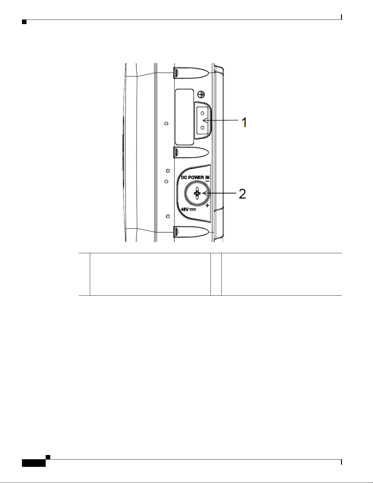
Figure 1-5 Left Side Connectors on All Models
1 Ground Pad. 2 DC Power-In (covered).
If the port is not in use, then the covering plug
must be tightened to 12.5 lbf-in torque.
Otherwise, it may lead to water leaking into
the access point.
1-9
Cisco Aironet 1560 Series Outdoor Access Point Hardware Installation Guide
Chapter 1 Overview
Hardware Features
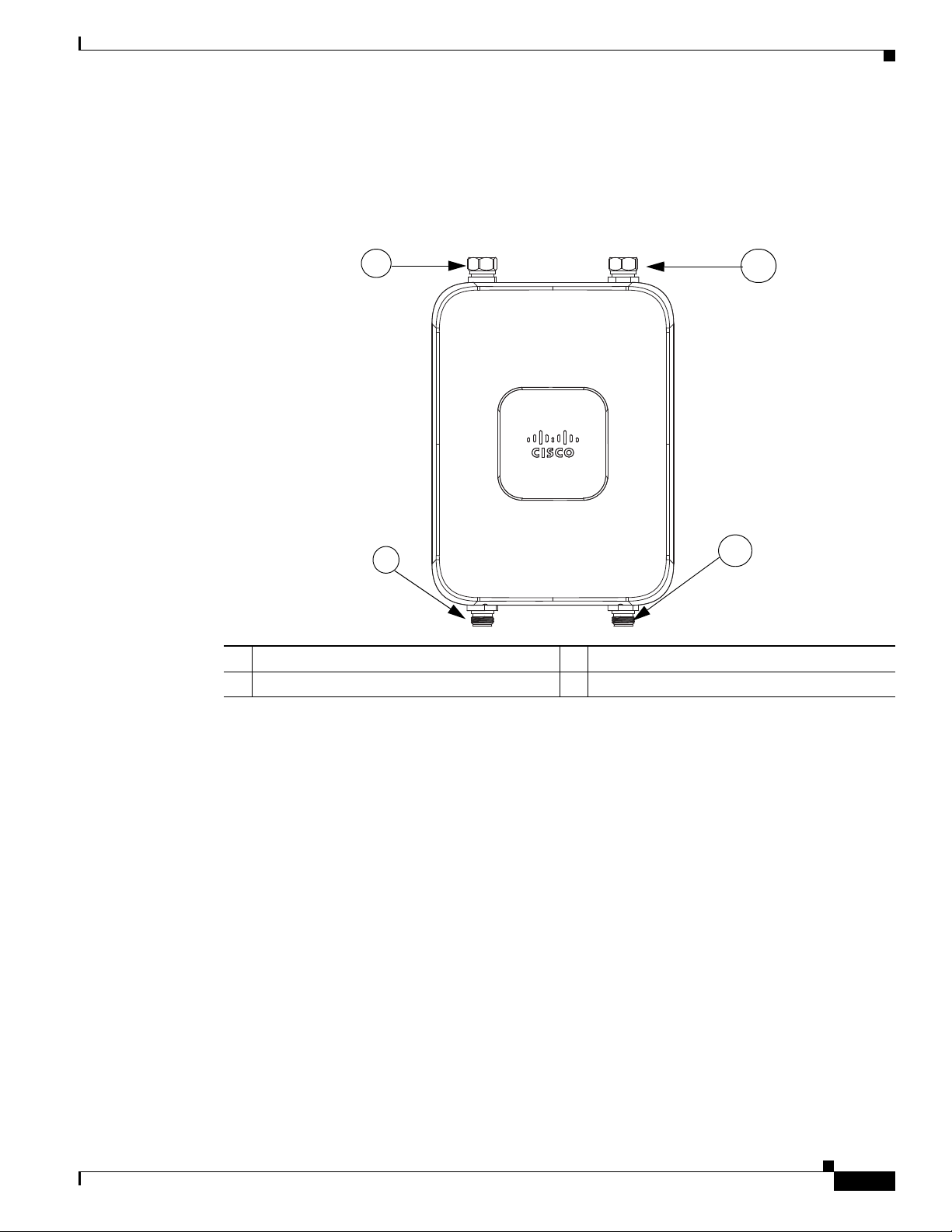
External Antenna Port Locations on AP1562E
Figure 1-6 shows the antenna port locations for model AP1562E. The ports used depend on the optional
antennas ordered.
Figure 1-6 External Antenna Port Locations for Access Point Model AP1562E
AP1562I (Internal Antenna)
The 1562I access point 802.11b/g/n radio is used primarily for local access and its 802.11a/n/ac radio
for wireless backhaul in the Mesh.
The 2 GHz b/g/n radio operates in 2.4 GHz ISM band. It supports channels 1-11 in the US, 1-13 in
Europe, and 1-13 in Japan. It has 3 transmitters with a maximum total output power of 29 dBm for
802.11b/g/n operation. Output power is configurable for 8 levels in 3 dB steps. It has three receivers that
enable maximum-ratio combining (MRC).
The 5 GHz a/n radio operates in the UNII-1 band (5.15-5.25 GHz), UNII-2 band (5.25 - 5.35 GHz),
UNII-2 Extended/ETSI band (5.47 - 5.725 GHz), and the upper ISM band (5.725 - 5.850 GHz). It has
two transmitters with a maximum total output power of 27 dBm depending on the regulatory domain.
The total maximum output power for the upper ISM band is 27 dBm for A-domain. Tx power settings
will change depending on the regulatory domain. Output power is configurable in 3 dB steps. Its three
receivers enable maximum-ratio combining (MRC).
The 1562I access point is equipped with three integrated dual-band antennas with 3 dBi gain at 2 GHz
and 5 dBi gain at 5 GHz.
351321
4
2
3
1
1 Antenna port 1 – Type N connector 2 Antenna port 2- Type N connector
3 Antenna port 3– Type N connector (with cap) 4 Antenna port 4- Type N connector (with cap)
1-10
Cisco Aironet 1560 Series Outdoor Access Point Hardware Installation Guide
Chapter 1 Overview
Hardware Features
AP1562E (External Antenna)
The 1562E access point is equipped with four N-type RF connectors. The 1562E can be configured via
software to support dual band or single band antennas. When configured for dual band antennas, antenna
ports 1 and 2 on the bottom of the unit (Figure 1-2) are used to support multiple input/multiple output
(MIMO) operation on both 2.4 and 5 GHz radios. When using the Cisco Aironet AIR-ANT2547V-N or
AIR-ANT2547VG-N omindirectional antennas, the antenna can be connected directly to the access
point (Figure 2-19). If the antennas are remotely located, an appropriate low loss RF cable should be
used.
Note Ensure that the antenna band mode is configured before the 1562E access point is installed.
When configured for single band antennas, antenna port 1 and antenna port 2 support MIMO operation
for the 2.4 GHz radio, and antenna ports 3 and 4 (Figure 1-3) support MIMO on the 5 GHz radio. See
the Cisco Wireless LAN Controller Configuration Guide for information on the software configuration.
Multiple Power Sources
The 1560 series access point supports these power sources:
• DC power – 42-57 VDC
• Power over Ethernet (PoE) – For more information, see “Powering the Access Point” section on
page 2-47.
Warning
Installation of the equipment must comply with local and national electrical codes.
Statement 1074
Warning
This equipment must be externally grounded using a customer-supplied ground wire before power is
applied. Contact the appropriate electrical inspection authority or an electrician if you are uncertain
that suitable grounding is available.
Statement 366
Warning
Do not work on the system or connect or disconnect cables during periods of lightning activity.
Statement 1001
Warning
Connect the unit only to DC power source that complies with the safety extra-low voltage (SELV)
requirements in IEC 60950 based safety standards.
Statement 1033
Warning
To reduce the risk of fire, use only No. 26 AWG or larger telecommunication line cord.
Statement 1023
Caution Several forms of PoE are supported. See Table Tabl e 2-9 for the PoE options and their corresponding
modes of operation.
1-11
Cisco Aironet 1560 Series Outdoor Access Point Hardware Installation Guide
Chapter 1 Overview
Hardware Features
Caution Do not place the power injector in an unprotected outdoor environment because water could get into the
power injector and cause a short circuit and possible fire.
Caution When the access point is installed outdoors or in a wet or damp location, the AC branch circuit that is
powering the access point should be provided with ground fault protection (GFCI), as required by Article
210 of the National Electrical Code (NEC).
Power injectors
The 1560 series access points support the following power injectors:
• AIR-PWRINJ-60RGD1
• AIR-PWRINJ-60RGD2
• AIR-PWRINJ-30RGD1
Warning
To reduce the risk of fire, use only No. 26 AWG or larger telecommunications line cord.
Statement 1023
Caution When the access point is installed outdoors, or in a wet or damp location, the AC branch circuit that is
powering the access point should be provided with ground fault protection (GFCI), as required by Article
210 of the National Electrical Code (NEC).
Ethernet (PoE) Ports
The access point supports an Ethernet uplink port (PoE-In). The access point Ethernet uplink port uses
an RJ-45 connector (with weatherproofing) to link the access point to the 10BASE-T, 100BASE-T or
1000BASE-T network. The Ethernet cable is used to send and receive Ethernet data and to optionally
supply inline power from the power injector or a suitably powered switch port.
Tip The access point senses the Ethernet and power signals and automatically switches internal circuitry to
match the cable connections.
Warning
To reduce the risk of fire, use only No. 26 AWG or larger telecommunication line cord.
Statement 1023
The Ethernet cable must be a shielded outdoor rated Category 5e (CAT5e) or better cable. The access
point senses the Ethernet and power signals and automatically switches internal circuitry to match the
cable connections.
Optional Hardware
Depending on what you ordered, the following optional access point hardware may be part of your
shipment:

1-12
Cisco Aironet 1560 Series Outdoor Access Point Hardware Installation Guide
Chapter 1 Overview
Hardware Features
• External antennas, depending on which ones you purchased (See “AP1562E (External Antenna)”
section on page 1-10 for information on available external antennas.)
• Wall/Pole mount bracket AIR-ACC1530-PMK1(=)
• Wall/Pole mount bracket for AP and AC/DC power adapter AIR-ACC1560-PMK1(=)
• Wall/Pole mount bracket with tilt mechanism, spare only AIR-ACC1530-PMK2(=)
• Street light power tap (AIR-PWR-ST-LT-R3P=), works only with the AC/DC power adapter.
• Power injector AIR-PWRINJ6=
• AP cover / Solar Shield for 1560, spare only (AIR-ACC1560-CVR=)
• AC/DC power adapter, spare only AIR-PWRADPT-RGD1=
• AIR-PWRINJ-60-PMK= mounting bracket for AIR-PWRADPT-RGD1=
• Spare Parts kit containing extra cable glands, power connector, ground lug, etc.
(AIR-ACC1530-KIT1=)
• AIR-PWRINJ-60RGD1=
• AIR-PWRINJ-60RGD2=
• AIR-PWRINJ-30RGD1=
1-13
Cisco Aironet 1560 Series Outdoor Access Point Hardware Installation Guide
Chapter 1 Overview
Network Deployment Examples
Network Deployment Examples
The access point is a wireless device designed for wireless client access and point-to-point bridging,
point-to-multipoint bridging, and point-to-multipoint mesh wireless connectivity. The access point
provides 5-GHz backhaul capability to link with another access point to reach a wired network
connection or to provide repeater operations for other access points.
The access point plays two primary radio roles: a root access point (hereafter called a RAP) or a mesh
(non-root) access point (hereafter called a MAP), which is the default role of all access points. When the
access point has a fiber or wired Ethernet connection to the controller (through a switch), the radio role
is called a RAP. In order to be considered a RAP, the access point must be configured as a RAP. A RAP
is a parent node to any bridging or mesh network. A controller can support one or more RAPs, each one
parenting the same or different wireless networks. There can be more than one RAP for the same mesh
network for redundancy. RAPs and MAPs can support wireless clients on the 2.4-GHz and 5-GHz band.
Client access on 5-GHz is called universal client access.
When the access point does not have a wired Ethernet connection to the controller (through a switch),
the radio role is called a MAP. The MAPs have a wireless connection (through the backhaul interface)
to other MAPs and finally to a RAP which has an Ethernet connection through a switch to the controller.
MAPs may also have a wired Ethernet connection to a local LAN and serve as a bridge endpoint for that
LAN (using a point-to-point or point-to-multipoint bridge connection).
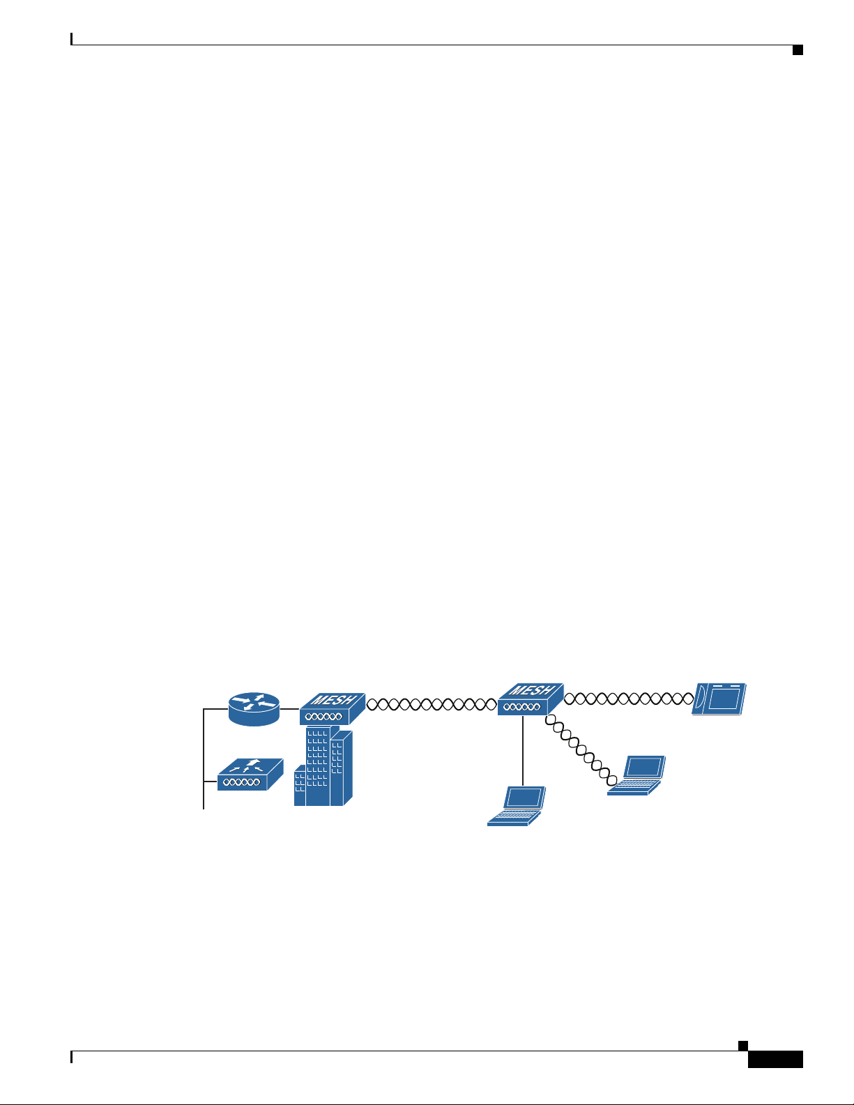
Wireless Backhaul
The access point supports wireless backhaul capability using the 5 GHz radio to bridge to another access
point to reach a wired network connection to a controller (see Figure 1-7). The access point connected
to the wired network is considered a RAP in this configuration. The remote access point is considered a
MAP and transfers wireless client traffic to the RAP for transfer to the wired network. Control And
Provisioning of Wireless Access Points (CAPWAP) control traffic is also transferred over this bridged
link.
Figure 1-7 Access Point Backhaul Example
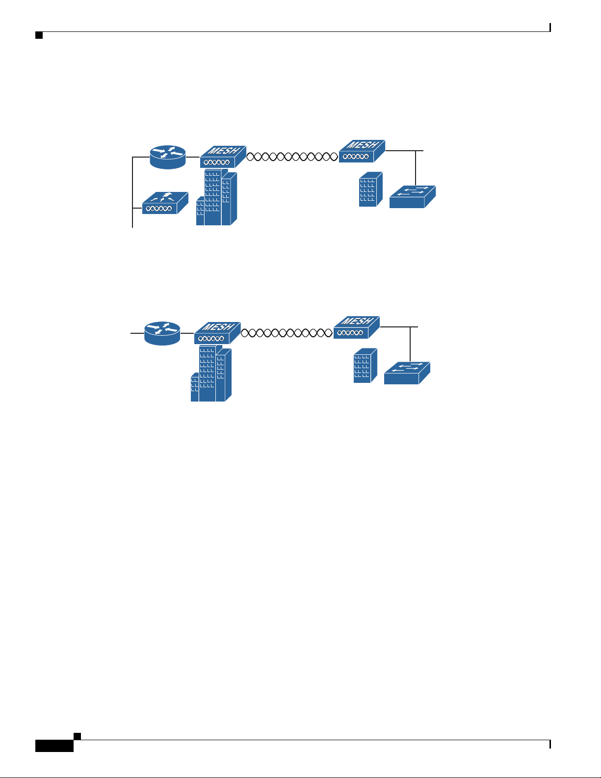
Point-to-Point Bridging
The access points can be used to extend a remote network by using the 5 GHz backhaul radio to bridge
the two network segments as shown in Figure 1-8. To support Ethernet bridging, you must enable
bridging on the controller for each access point. By default this capability is turned-off for all access
points.
255493
(5 GHz)
(2.4 GHz and 5 GHz)
1-14
Cisco Aironet 1560 Series Outdoor Access Point Hardware Installation Guide
Chapter 1 Overview
Network Deployment Examples
Wireless client access is supported; however, if bridging between tall buildings, the 2.4-GHz wireless
coverage area may be limited and possibly not suitable for direct wireless client access.
Figure 1-8 Access Point Point-to-Point Bridging Example
The access points can also support point-to-point bridging under autonomous mode. In this autonomous
mode, the bridging can be done on the 2.4 or 5 GHz radio, but not both. In this mode, one access point
is designated as the root and the other end is designated as the non-root bridge.
Figure 1-9 Access Point Point-to-Point Bridging in Autonomous Mode
Point-to-Multipoint Bridging
The access points can be used as a RAP to connect multiple remote MAPs with their associated wired
networks. By default this capability is turned-off for all access points. To support Ethernet bridging, you
must enable bridging on the controller for each access point. Wireless client access can be provided over
the bridging link; however, if bridging between tall buildings, the 2.4-GHz wireless coverage area may
be limited and possibly not suitable for direct wireless client access. Figure 1-10 illustrates an example
of access point-to-multipoint bridging.
255495
(5 GHz)
352052
2.4 GHz or 5 GHz
 Loading...