


 Loading...
. |
|
WIRING DIAGRAMS 8W - 1 |
|
WIRING DIAGRAMS
CONTENTS
|
page |
|
page |
COMPONENT IDENTIFICATION . . . . . . . . . . . . |
. 11 |
SPLICE LOCATIONS . . . . . . . . . . . . . . . . . . . . |
. 33 |
GENERAL INFORMATION . . . . . . . . . . . . . . . . |
. . 1 |
WIRING DIAGRAMS AS-BODY H-K . . . . . . . . . |
. 47 |
GENERAL INFORMATION
INDEX
|
page |
Component Identification . . . . . . . . . . . . . . . . . . |
. . 3 |
Connectors . . . . . . . . . . . . . . . . . . . . . . . . . . . . |
. . 4 |
Distributor Secondary Wiring . . . . . . . . . . . . . . . |
. . 1 |
Fusible Links . . . . . . . . . . . . . . . . . . . . . . . . . . . |
. . 4 |
Harness Repair . . . . . . . . . . . . . . . . . . . . . . . . . |
. . 4 |
Locating a System . . . . . . . . . . . . . . . . . . . . . . . |
. . 2 |
The wiring diagrams contain the latest information at the time of publication.
Throughout this group references may be made to a particular vehicle by letter or number designation. A chart showing the breakdown of these designations is included in the Introduction Section at the front of this service manual.
|
page |
Main Circuit Identification . . . . . . . . . . . . . . . . . . |
. . 2 |
Splice Locations . . . . . . . . . . . . . . . . . . . . . . . . |
. . 3 |
Symbols, Fuses and Abbreviations . . . . . . . . . . . |
. . 6 |
Troubleshooting Wiring Problems . . . . . . . . . . . . |
. . 4 |
Wire Code Identification . . . . . . . . . . . . . . . . . . . |
. . 2 |
Wiring Diagram Sheets and Indexes . . . . . . . . . . |
. . 1 |
located at the lower right or left hand corner of each sheet, page numbers at the top of each page do not apply to diagram sheets.
Diagram sheets show all information relating to the system. This includes feeds, grounds, switch internal circuity, connectors, splices, and pin identification for controllers and modules.
DISTRIBUTOR SECONDARY WIRING
Fig. 1 Distributor Secondary Wiring Ð 2.5L Engine
Distributor secondary wiring is shown in Figures 1, 2, 3, and 4. For additional information on ignition systems or distributor operation refer to Group 8D Ignition Systems, in this manual.
WIRING DIAGRAM SHEETS AND INDEXES
The wiring diagram sheets are organized in such a manner that systems relating to the basic vehicle and all of its options are shown, add-on or non-factory options are not covered. Diagram pages are identified by a sheet number which is
Fig. 2 Distributor Cap Ð 3.0L V6 Engine
In certain instances a wire may be referenced to another sheet. When this happens, the wire will be
8W - 2 WIRING DIAGRAMS |
|
. |
|
Fig. 3 Distributor Secondary Wiring Ð 3.0L V6 En-
gine
Fig. 4 Ignition System Secondary Wiring 3.3L V6
Engine
identified as to what it is ie: feed, ground, etc, and where its going (Fig. 5). This has been done to aid in the diagnosis of wiring and component problems.
The index used for the diagrams is located at the beginning of the diagrams and covers all systems shown in the diagrams. The index is in alphabetical order and identifies the main system and all related components.
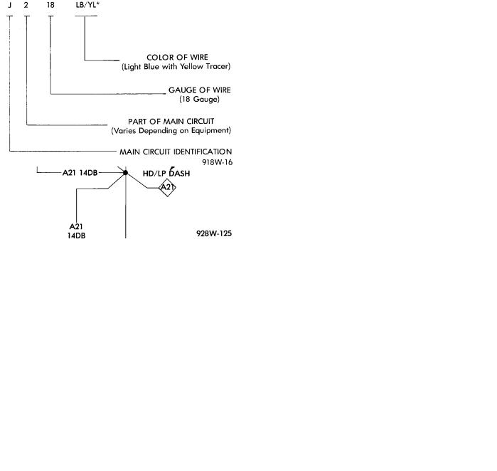
WIRE CODE IDENTIFICATION
Each wire shown in the diagrams contains a code (Fig. 6) which identifies the main circuit, part of the main circuit, gauge of wire, and color. The color is shown as a two letter code which can be identified by referring to the Wire Color Code Chart (Fig. 7). If the wire has a tracer and it is a standard color an asterisk will follow the main wire color. If the tracer is non-
Fig. 5 Wiring Diagram Page Sample
standard the main wire color will have a slash (/) after it followed by the tracer color.
Fig. 6 Wire Color Code Identification
MAIN CIRCUIT IDENTIFICATION
To identify which main circuit code applies to a system, refer to the Main Circuit Identification Code Chart. This chart shows the main feed circuits only and does not show the secondary codes that may apply to some vehicles.
LOCATING A SYSTEM
To locate a system or component in the diagrams, refer to the alphabetical index at the front of the diagrams. Determine the diagram sheet number. Sheet numbers are located at the lower right or left hand corner of each sheet. Page numbers at the top of the page do not apply to diagram sheets.

. |
|
WIRING DIAGRAMS 8W - 3 |
|
Fig. 7 Wire Color Code Chart
The diagram index identifies the main system and all components that relate to that system. There are also sections of the index that identify specific components only (for example modules, lamps, etc.). Refer to a components name in the index if you are unclear as to what a system may be called.
Diagram pages are arranged starting with the battery and fuses. Then working into charging, starting, and ignition systems. After this they start at the front of the vehicle and work to rear of the vehicle. The diagrams end with connector identification pages.
Fig. 8 Wiring Splice Examples
COMPONENT IDENTIFICATION
When looking for a components actual location on the vehicle refer to the wiring and components section index. This section shows the wire harness routing and the components location in the vehicle. When using this section refer to the wiring diagrams for the general location of the component. Then use the component identification index to locate the proper figure number.
SPLICE LOCATIONS
Splice locations are indicated in the diagrams by a diamond with a splice circuit code within it (Fig. 8 example 1). If there is more than one splice per circuit a small box will be connected to it with the splice number in it (Fig. 8 example 2).
To locate a splice in the wiring harness determine the splice number from the wiring diagrams then refer to the splice location index. This section shows the general location of the splice in the harness.
The wiring diagrams also indicate what harness the splice is located in. To identify the harness an abbreviated call out is placed next to the main splice (Fig. 5).
8W - 4 WIRING DIAGRAMS
CONNECTORS
The connectors shown in the diagram sheets are viewed from the terminal end unless otherwise specified. For viewing bulkhead, engine controller, and transmission controller connectors refer to the rear of the wiring diagrams. This area shows major connectors and identifies pin and cavity information.
TROUBLESHOOTING WIRING PROBLEMS
When troubleshooting wiring problems there are six steps which can aid in the procedure. The steps are listed and explained below.
(1)Verify the problem.
(2)Verify any related symptoms. Do this by performing operational checks on components that are in the same circuit as the problem area. Refer to the wiring diagrams fuse application chart for more information.
(3)Analyze the symptoms. Use the wiring diagrams to determine what the circuit is doing, where the problem most likely is occurring and where the diagnosis will continue.
(4)Isolate the problem area.
(5)Repair the problem.
(6)Verify proper operation. For this step check for proper operation of all items on the circuit repaired. Refer to the wiring diagram fuse application chart.
FUSIBLE LINKS
Vehicle wiring harnesses are equipped with fusible links to protect against harness damage in the event of a short in the system. Fusible links are color coded to indicate wire gauge and size. Refer to the fusible link chart for color and gauge identification (Fig. 9).
.
When a fusible link blows it is important to find out what the problem is. They are placed in the electrical system for protection against shorts to ground which can be caused by a component failure or various wiring failures. Do not just replace the fusible link to correct the problem.
When diagnosing a faulty fusible link it is important to check the wire carefully. In some instances the link may be blown and it will not show through the insulation, the wire should be checked over its entire length for internal breaks.
(1)Disconnect battery negative cable.
(2)Cut out the blown portion of the fusible link.
(3)Strip 1 inch of insulation from each end of the existing fusible link.
(4)Place a piece of heat shrink tubing over one of side of the fusible link. Make sure the tubing will be long enough to cover and seal the entire repair area.
(5)Cut a replacement piece of fusible link approximately two inches longer than the piece removed.
(6)Remove one inch of insulation from each end of the replacement fusible link.
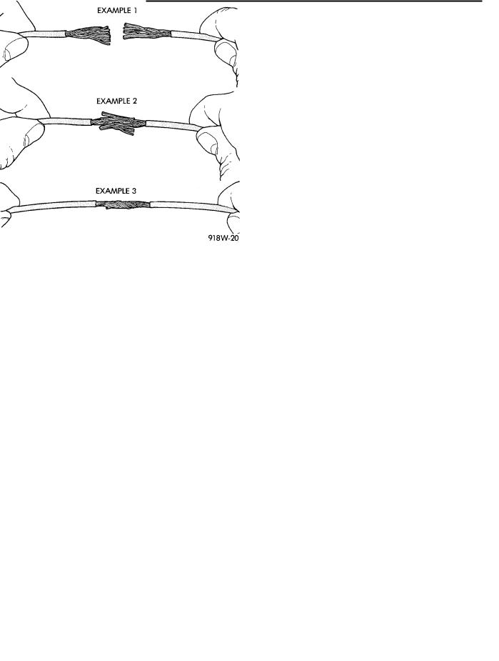
(7)Spread the strands of wire apart on each of the exposed wires (Fig. 10 example 1).
(8)Push the two ends of the wire together until the strands of wire are close to the insulation (Fig. 10 example 2).
(9)Twist the wires together (Fig. 10 example 3).
(10)Solder the wires together using rosin core type solder only. Do not use acid core type solder.
(11)Center the heat shrink tubing over the joint and heat using a heat gun. Heat the joint until the tubing is tightly sealed and sealant comes out of both ends of the tubing.
Fig. 9 Fusible Link Chart
HARNESS REPAIR
FUSIBLE LINK REPLACEMENT
CAUTION: Do not replace blown fusible links with a |
|
standard wire. Only use fusible type wire with hypa- |
|
lon insulation or damage to the electrical system |
|
could occur. Also make sure correct gauge of wiring |
|
is used. Refer to the wiring diagrams for proper |
|
gauge and color. |
Fig. 10 Wire Repair |
.
(12)Secure the fusible link to the existing ones to prevent chafing or damage to the insulation.
(13)Connect battery and test all affected systems.
WIRING REPAIR
When replacing or repairing a wire, it is important that the correct gauge be used as shown in the wiring diagrams. The wires must also be held securely in place to prevent damage to the insulation.
(1)Disconnect battery negative cable.
(2)Remove 1 inch of insulation from each end the
wire.
(3)Place a piece of heat shrink tubing over one of side of the wire. Make sure the tubing will be long enough to cover and seal the entire repair area.
(4)Spread the strands of the wire apart on each part of the exposed wires (Fig. 10 example 1).
(5)Push the two ends of wire together until the strands of wire are close to the insulation (Fig. 10 example 2).
(6)Twist the wires together (Fig. 10 example 3).
(7)Solder the connection together using rosin core type solder only. Do not use acid core solder.
(8)Center the heat shrink tubing over the joint and heat using a heat gun. Heat the joint until the tubing is tightly sealed and sealant comes out of both ends of the tubing.
(9)Secure the wire to the existing ones to prevent chafing or damage to the insulation.
(10)Connect battery and test all affected systems.
CONNECTOR REPLACEMENT
(1)Disconnect battery.
(2)Disconnect the connector that is to be repaired from its mating half.
(3)Remove connector locking wedge (Fig. 11).
Fig. 11 Connector Locking Wedge Tab
(4)Position the connector locking finger away from the terminal while pulling on the wire to remove the terminal from the connector (Fig. 12).
(5)Reset the terminal locking tang, if it has one.
WIRING DIAGRAMS 8W - 5
(6)Insert the removed wire in the same cavity on the repair connector.
(7)Repeat steps four thru six for each wire in the connector, being sure that all wires are inserted into the proper cavities. For additional connector pin out identification refer to the wiring diagrams.
(8)Insert the connector locking wedge into the repaired connector.
(9)Connect connector to its mating half.
(10)Connect battery and test all affected systems.
Fig. 12 Connector Locking Finger and Locking
Wedge
CONNECTOR AND TERMINAL ASSEMBLY REPLACEMENT
(1)Disconnect Battery.
(2)Disconnect the connector being repaired from its mating half.
(3)Cut off the existing wire connector directly behind the insulator and remove six inches of tape from the harness.
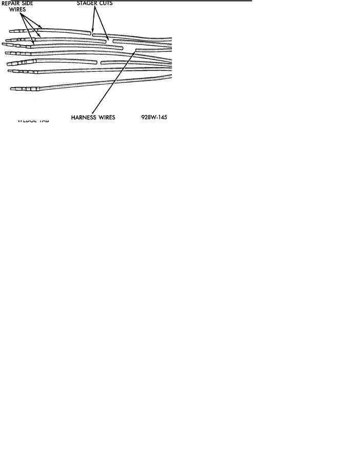
(4)Stagger cut all wires on the harness side about 1/2 inch apart (Fig. 13).
Fig. 13 Stagger Cutting Wires

8W - 6 WIRING DIAGRAMS
(5)Remove 1 inch of insulation from each wire on the harness side.
(6)Stagger cut the matching wires on the repair connector assembly in the opposite order as was done on the harness side of the repair (allow extra length for soldered connections). Check that the overall length is the same as the original (Fig. 13).
(7)Remove 1 inch of insulation from each wire.
(8)Place a piece of heat shrink tubing over one of side of the wire. Make sure the tubing will be long enough to cover and seal the entire repair area.
(9)Spread the strands of the wire apart on each part of the exposed wires (Fig. 10 example 1).
(10)Push the two ends of wire together until the strands of wire are close to the insulation (Fig. 10 example 2).
(11)Twist the wires together (Fig. 10 example 3).
(12)Solder the connection together using rosin core type solder only. Do not use acid core solder.
(13)Center the heat shrink tubing over the joint and heat using a heat gun. Heat the joint until the tubing is tightly sealed and sealant comes out of both ends of the tubing.
(14)Repeat steps 8 thru 13 for each wire.
(15)Re-tape the wire harness starting 1-1/2 inches behind the connector and 2 inches past the repair.
(16)Reconnect the repaired connector.
(17)Connect battery and test all affected systems.
TERMINAL REPLACEMENT
(1)Disconnect battery.
(2)Disconnect the connector being repaired form its mating half.
(3)Remove connector locking wedge (Fig. 11).
(4)Position the connector locking finger away from the terminal while pulling on the wire to remove the terminal from the connector (Fig. 12).
(5)Cut the wire 6 inches from the back of the connector.
(6)Remove 1 inch of insulation from the wire on the harness side.
(7)Select a wire from the terminal repair assembly that best matches the color wire being repaired.
.
(8)Cut the repair wire to the proper length and remove 1 inch of insulation.
(9)Place a piece of heat shrink tubing over one of side of the wire. Make sure the tubing will be long enough to cover and seal the entire repair area.
(10)Spread the strands of the wire apart on each part of the exposed wires (Fig. 10 example 1).
(11)Push the two ends of wire together until the strands of wire are close to the insulation (Fig. 10 example 2).
(12)Twist the wires together (Fig. 10 example 3).
(13)Solder the connection together using rosin core type solder only. Do not use acid core solder.
(14)Center the heat shrink tubing over the joint and heat using a heat gun. Heat the joint until the tubing is tightly sealed and sealant comes out of both ends of the tubing.
(15)Insert the repaired wire into the connector.
(16)Install the connector locking wedge and reconnect the connector to its mating half.
(17)Re-tape the wire harness starting 1-1/2 inches behind the connector and 2 inches past the repair.
(18)Connect battery and test all affected systems.
SYMBOLS, FUSES AND ABBREVIATIONS
Various symbols are used throughout the wiring diagrams. These symbols can be identified by referring to the symbol identification chart (Fig. 14).
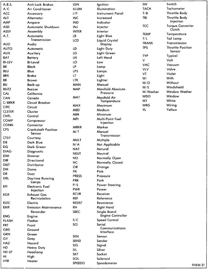
Certain abbreviations are also used in the diagrams. These have been developed in such a way that there meaning should be clear. Refer to the abbreviations chart for an explanation of the terms used (Fig. 15).
For fuse and relay bank information refer to (Fig 16).
CAUTION: When replacing a blown fuse it is important to replace it with a fuse having the correct amperage rating. The use of a fuse with a rating other than indicated may result in an electrical overload. If a proper rated fuse continues to blow, it indicates a problem that should be corrected.

. |
|
WIRING DIAGRAMS 8W - 7 |
|
Fig. 14 Symbol Identification
8W - 8 WIRING DIAGRAMS |
|
. |
|
Fig. 15 Abbreviation Chart

. |
|
WIRING DIAGRAMS 8W - 9 |
|
Fig. 16 Fuse Block and Relay Bank AS
8W - 10 WIRING DIAGRAMS |
|
. |
|
. |
|
WIRING DIAGRAMS 8W - 11 |
|
COMPONENT IDENTIFICATION
Caption |
Fig. |
Body Wiring Left Side . . . . . . . . . . . . . . . . . . . . . . . . . . .1
Body Wiring Right Side . . . . . . . . . . . . . . . . . . . . . . . .6, 7
Door Wiring (Body) . . . . . . . . . . . . . . . . . . . . . . . . . . . .9
Door Wiring . . . . . . . . . . . . . . . . . . . . . . . . . . . . . . . .10
Engine Compartment Wiring 2.5L . . . . . . . . . . . . . . . . . . .19
Engine Compartment Wiring 3.0L . . . . . . . . . . . . . . . . . . .20
Engine Compartment Wiring 3.3L . . . . . . . . . . . . . . . .21, 22
Engine Wiring 2.5L . . . . . . . . . . . . . . . . . . . . . . . . . . . .26
Engine Wiring 3.0L . . . . . . . . . . . . . . . . . . . . . . . . . . . .27
Engine Wiring 3.3L . . . . . . . . . . . . . . . . . . . . . . . . . . . .28
Front End Wiring . . . . . . . . . . . . . . . . . . . . . . . . . . . . .16
Fuel Tank/AWD Wiring . . . . . . . . . . . . . . . . . . . . . . . . . .14
Ground Strap Locations . . . . . . . . . . . . . . . . . . . . . . . . .18
Caption |
Fig. |
Instrument Panel Wiring . . . . . . . . . . . . . . . . . . . . . . . |
.12 |
Instrument Panel Wiring (Connections) . . . . . . . . . . . . . . |
.13 |
Liftgate Wiring . . . . . . . . . . . . . . . . . . . . . . . . . . . . . |
.15 |
Overhead Console Wiring . . . . . . . . . . . . . . . . . . . . . . |
. .4 |
Power Seat Wiring . . . . . . . . . . . . . . . . . . . . . . . . . . . |
. .8 |
Rear A/C Heater Wiring . . . . . . . . . . . . . . . . . . . . . . . . |
. .5 |
Roof Wiring Left Side . . . . . . . . . . . . . . . . . . . . . . . . . |
. .2 |
Roof Wiring Right Side . . . . . . . . . . . . . . . . . . . . . . . . |
. .3 |
Steering Column Wiring . . . . . . . . . . . . . . . . . . . . . . . . |
.11 |
Transmission Wiring 2.5L . . . . . . . . . . . . . . . . . . . . . . |
.23 |
Transmission Wiring 3.0L . . . . . . . . . . . . . . . . . . . . . . |
.24 |
Transmission Wiring 3.3L . . . . . . . . . . . . . . . . . . . . . . |
.25 |
Underhood Lamp Wiring . . . . . . . . . . . . . . . . . . . . . . . |
.17 |

8W - 12 WIRING DIAGRAMS |
|
. |
|
Fig. 1 Body Left Side Wiring
. |
|
WIRING DIAGRAMS 8W - 13 |
|
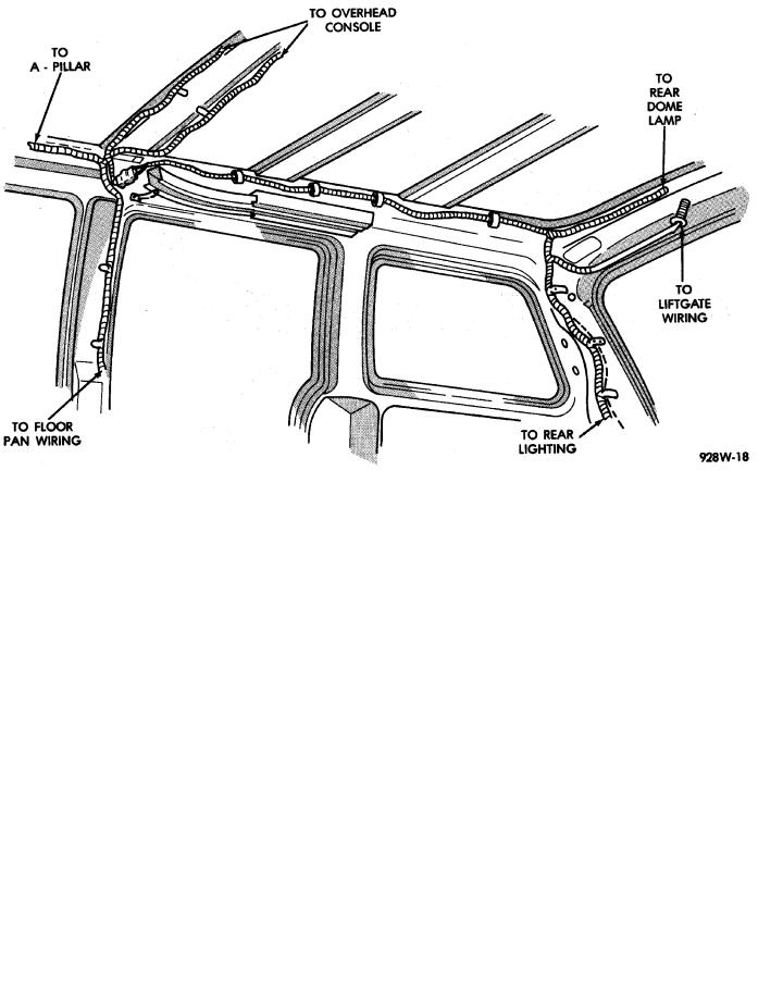
Fig. 2 Roof Wiring Left Side
Fig. 3 Roof Wiring Right Side
8W - 14 WIRING DIAGRAMS |
|
. |
|
Fig. 4 Overhead Console Wiring
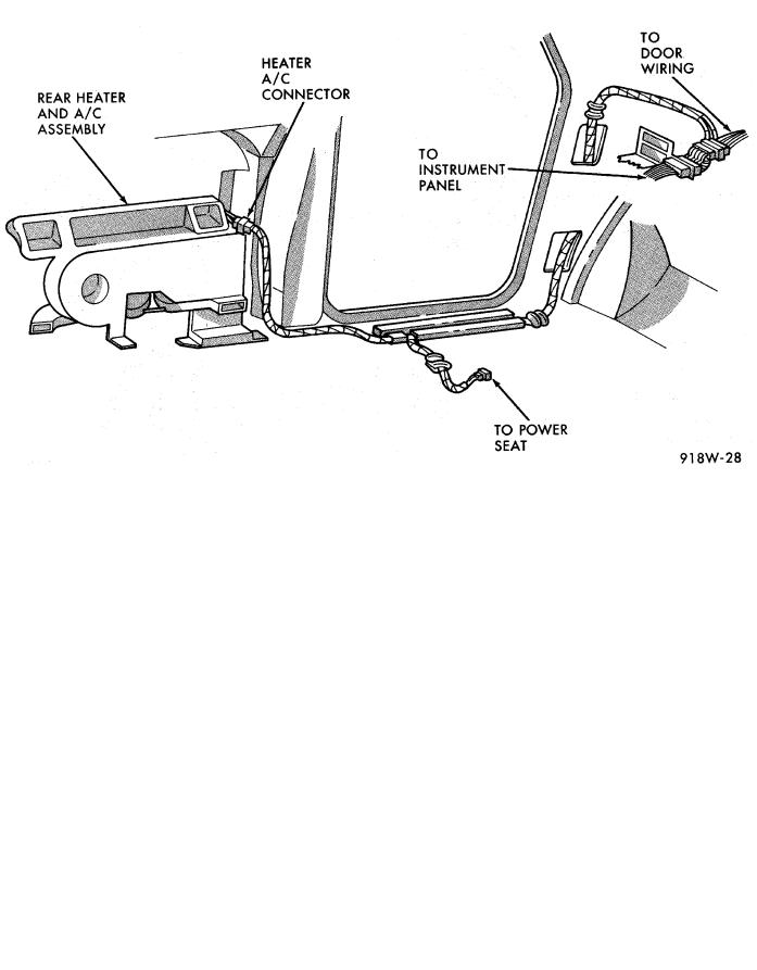
Fig. 5 Rear A/C Heater Wiring
. |
|
WIRING DIAGRAMS 8W - 15 |
|
Fig. 6 Body Wiring Right Side
Fig. 7 Body Wiring Right Side
8W - 16 WIRING DIAGRAMS |
|
. |
|
Fig. 8 Power Seat Wiring
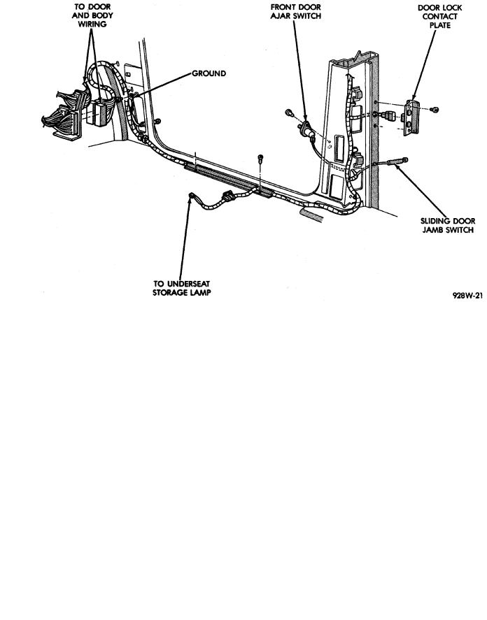
Fig. 9 Door Wiring (Body Side)
. |
|
WIRING DIAGRAMS 8W - 17 |
|
Fig. 10 Door Wiring
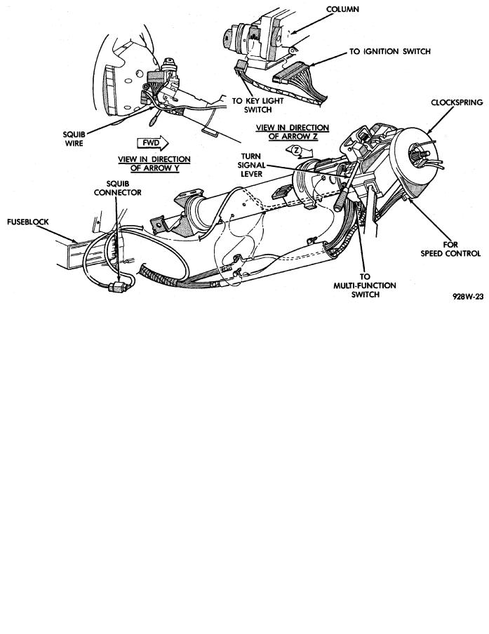
Fig. 11 Steering Column Wiring

8W - 18 WIRING DIAGRAMS |
|
. |
|
Fig. 12 Instrument Panel Wiring

. |
|
WIRING DIAGRAMS 8W - 19 |
|
Instrument Panel Wiring (Connections)

8W - 20 WIRING DIAGRAMS |
|
. |
|
Fig. 14 Fuel Tank/AWD Wiring
. |
|
WIRING DIAGRAMS 8W - 21 |
|
Fig. 15 Liftgate Wiring
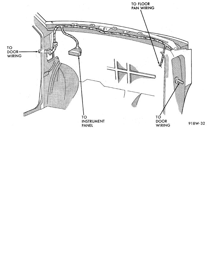
Fig. 16 Front End Wiring
8W - 22 WIRING DIAGRAMS |
|
. |
|
Fig. 17 Underhood Lamp Wiring
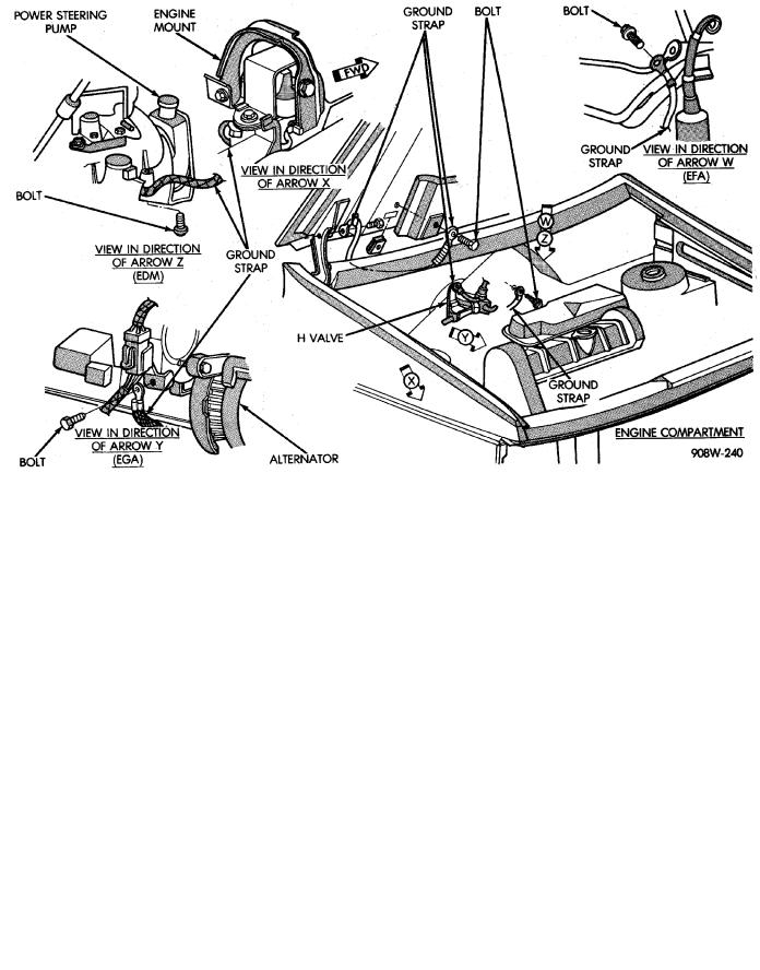
Fig. 18 Ground Strap Locations

. |
|
WIRING DIAGRAMS 8W - 23 |
|
Fig. 19 Engine Compartment Wirign 2.5L

8W - 24 WIRING DIAGRAMS |
|
. |
|
Fig. 20 Engine Compartment Wirign 3.0L

. |
|
WIRING DIAGRAMS 8W - 25 |
|
Fig. 21 Engine Compartment Wiring 3.3L

8W - 26 WIRING DIAGRAMS |
|
. |
|
Fig. 22 Engine Compartment Wiring 3.3L (Right Side)

. |
|
WIRING DIAGRAMS 8W - 27 |
|
Fig. 23 Transmission Wiring 2.5L

8W - 28 WIRING DIAGRAMS |
|
. |
|
Fig. 24 Transmission Wiring 3.0L

. |
|
WIRING DIAGRAMS 8W - 29 |
|
Fig. 25 Trnasmission Wiring 3.3L

8W - 30 WIRING DIAGRAMS |
|
. |
|
Fig. 26 Engine Wiring 2.5L
Loading...