


200 - 2014
Table of contents
 Loading...
THE CHRYSLER
2014 USER GUIDE

IF YOU ARE THE FIRST REGISTERED RETAIL OWNER OF YOUR
VEHICLE, YOU MAY OBTAIN A COMPLIMENTARY PRINTED COPY
OF THE OWNER’S MANUAL, NAVIGATION/UCONNECT® MANUALS
OR WARRANTY BOOKLET BY CALLING --- (U.S.) OR
--- (CANADA) OR BY CONTACTING YOUR DEALER.
The driver’s primary responsibility is the safe operation of the vehicle. Driving while distracted can
result in loss of vehicle control, resulting in a collision and personal injury. Chrysler Group LLC
strongly recommends that the driver use extreme caution when using any device or feature that
may take their attention o the road. Use of any electrical devices such as cell phones, computers,
portable radios, vehicle navigation or other devices by the driver while the vehicle is moving is
dangerous and could lead to a serious collision. Texting while driving is also dangerous and should
never be done while the vehicle is moving. If you find yourself unable to devote your full attention
to vehicle operation, pull o the road to a safe location and stop your vehicle. Some States or
Provinces prohibit the use of cellular telephones or texting while driving. It is always the driver’s
responsibility to comply with all local laws.
IMPORTANT: This User Guide is intended to familiarize you with the important features of
your vehicle. The DVD enclosed contains your Owner’s Manual, Navigation/Uconnect®
Manuals, Warranty Booklets, Tire Warranty and Roadside Assistance (new vehicles
purchased in the U.S.) or Roadside Assistance (new vehicles purchased in Canada) in
electronic format. We hope you find it useful. Replacement DVD kits may be purchased by
visiting www.techauthority.com. Copyright 2013 Chrysler Group LLC.

TABLE OF CONTENTS
INTRODUCTION/WELCOME
WELCOME FROM CHRYSLER
GROUPLLC ..................2
CONTROLS AT A GLANCE
DRIVER COCKPIT ...............4
INSTRUMENT CLUSTER ...........6
GETTING STARTED
KEYFOB ....................8
REMOTE START ................9
TRUNK LOCK AND RELEASE ........9
SECURITY ALARM ..............10
SEATBELT ...................10
SUPPLEMENTAL RESTRAINT SYSTEM
(SRS)—AIRBAGS ...............11
CHILD RESTRAINTS .............12
FRONTSEATS ................15
REAR SEATS ..................17
HEATEDSEATS ................17
TILT/TELESCOPING STEERING
COLUMN ...................18
OPERATING YOUR VEHICLE
ENGINE BREAK-IN
RECOMMENDATIONS ............19
TURN SIGNAL/LIGHTS LEVER . . . ....20
WIPER/WASHER LEVER ...........21
SPEED CONTROL ..............22
MANUAL CLIMATE CONTROLS .....24
AUTOMATIC TEMPERATURE
CONTROLS (ATC) ..............25
POWER SUNROOF .............26
WIND BUFFETING . . ............27
ELECTRONICS
YOUR VEHICLE'S SOUND SYSTEM ....28
Uconnect® 130 .................30
Uconnect® 130 WITH SiriusXM
SATELLITE RADIO ..............32
Uconnect® 430/430N ..............35
Uconnect® 730N . ...............44
SiriusXM SATELLITE RADIO/TRAVEL
LINK.......................55
STEERING WHEEL AUDIO CONTROLS
SETTING THE ANALOG CLOCK .....59
iPod®/USB/MP3 CONTROL .........60
Uconnect® PHONE ...............61
Uconnect® VOICE COMMAND . . .....64
Bluetooth® STREAMING AUDIO ......66
ELECTRONIC VEHICLE INFORMATION
CENTER (EVIC ) ...............67
PROGRAMMABLE FEATURES .......67
UNIVERSAL GARAGE DOOR OPENER
(HomeLink®) ..................69
POWER OUTLETS . .............72
..59
UTILITY
TRAILER TOWING WEIGHTS
(MAXIMUM TRAILER WEIGHT
RATINGS) ...................73
RECREATIONAL TOWING
(BEHIND MOTORHOME, ETC.) ......74
WHAT TO DO IN EMERGENCIES
ROADSIDE ASSISTANCE ..........75
INSTRUMENT CLUSTER WARNING
LIGHTS ....................75
IF YOUR ENGINE OVERHEATS . . . . . . 79
JACKING AND TIRE CHANGING .....80
BATTERY LOCATION ............86
JUMP-STARTING ...............86
SHIFT LEVER OVERRIDE ..........89
TOWING A DISABLED VEHICLE .....89
FREEING A STUCK VEHICLE .......90
EVENT DATA RECORDER (EDR) . . ....91
MAINTAINING YOUR VEHICLE
OPENING THE HOOD . . . ........92
ENGINE COMPARTMENT .........93
FLUIDSANDCAPACITIES .........95
MAINTENANCE SCHEDULE ........97
MAINTENANCE RECORD . ........100
FUSES .....................101
TIRE PRESSURES ...............103
WHEEL AND WHEEL TRIM CARE ....104
EXTERIOR BULBS ..............104
CONSUMER ASSISTANCE
CHRYSLER GROUP LLC
CUSTOMER CENTER ...........105
CHRYSLER CANADA INC.
CUSTOMER CENTER ...........105
ASSISTANCE FOR THE HEARING
IMPAIRED ..................105
PUBLICATIONS ORDERING ........105
REPORTING SAFETY DEFECTS IN
THEUNITEDSTATES ............106
MOPAR® ACCESSORIES
AUTHENTIC ACCESSORIES
BYMOPAR® .................107
INDEX
...................108
FREQUENTLY ASKED
QUESTIONS
FAQ’s ......................111

INTRODUCTION/WELCOME
WELCOME FROM CHRYSLER GROUP LLC
Congratulations on selecting your new Chrysler Group LLCvehicle. Be assured that it represents
precision workmanship, distinctive styling, and high quality - all essentials that are traditional to
our vehicles.
Your new Chrysler Group LLC vehicle has characteristics to enhance the driver's control under
some driving conditions. These are to assist the driver and are never a substitute for attentive
driving. They can never take the driver's place. Always drive carefully.
Your new vehicle has manyfeatures for the comfortand convenience of you and your passengers.
Some of these should not be used when driving because they take your eyes from the road or
your attention fromdriving. Never text while driving or take your eyes morethan momentarily off
the road.
This guide illustrates and describes the operation of features and equipment that are either
standard or optional on this vehicle. This guide may also include a description of features and
equipment that are no longer available or were not ordered on this vehicle. Please disregard any
features and equipment described in this guide that are not available on this vehicle. Chrysler
Group LLC reserves the right to make changes in design and specifications and/or make
additions to or improvements to its products without imposing any obligation upon itself to install
them on products previously manufactured.
This User Guide has been prepared to help you quickly become acquainted with the important
features of your vehicle. It contains most things you will need to operate and maintain the vehicle,
including emergency information.
The DVD includes a computer application containing detailed owner's information which can be
viewed on a personal computer or MAC computer. The multimedia DVD also includes videos
which can be played on any standard DVD player (including the Uconnect® Touchscreen
Radios). Additional DVD operational information is located on the back of the DVD sleeve.
For complete owner information, refer to your Owner's Manual on the DVD in the owner’s
kit provided at the time of new vehicle purchase. For your convenience, the information
contained on the DVD may also be printed and saved for future reference.
Chrysler Group LLC is committed to protecting our environment and natural resources. By
converting from paper to electronic delivery for the majority of the user information for your
vehicle, together we greatly reduce the demand for tree-based products and lessen the stress on
our environment.
2
INTRODUCTION/WELCOME
VEHICLES SOLD IN CANADA
With respect to any vehicles sold in Canada, the name Chrysler Group LLC shall be deemed to
be deleted and the name Chrysler Canada Inc. used in substitution.
WARNING!
• Pedals that cannot move freely can cause loss of vehicle control and increase the risk of
serious personal injury.
• Always make sure that objects cannot fall into the driver foot well while the vehicle is
moving. Objects can become trapped under the brake pedal and accelerator pedal
causing a loss of vehicle control.
• Failure to properly follow floor mat installation or mounting can cause interference with
the brake pedal and accelerator pedal operation causing loss of control of the vehicle.
• Never leave children alone in a vehicle, or with access to an unlocked vehicle. Allowing
children to be in a vehicle unattended is dangerous for a number of reasons. A child or
others could be seriously or fatally injured. Children should be warned not to touch the
parking brake, brake pedal or the shift lever.
• Never use the ‘PARK’ position as a substitute for the parking brake. Always apply the
parking brake fully when parked to guard against vehicle movement and possible injury or
damage.
• Refer to your Owner's Manual on the DVD for further details.
USE OF AFTERMARKET PRODUCTS (ELECTRONICS)
The use of aftermarket devices including cell phones, MP3 players, GPS systems, or chargers
may affect the performance of on-board wireless features including Keyless Enter-N-Go™ and
Remote Start range. If you are experiencing difficulties with any of your wireless features, try
disconnecting your aftermarket devices to see if the situation improves. If your symptoms persist,
please see an authorized dealer.
CHRYSLER, DODGE, JEEP, RAM TRUCK, SRT, ATF+4, MOPAR and Uconnect are registered trademarks of Chrysler Group LLC.
COPYRIGHT ©2013 CHRYSLER GROUP LLC
3

CONTROLS AT A GLANCE
DRIVER COCKPIT
1. Electronic Vehicle Information Center (EVIC) Controls pg. 67
2. Turn Signal/Lights Lever (behind steering wheel) pg. 20
3. Instrument Cluster pg. 6
4. Electronic Vehicle Information Center (EVIC) Display pg. 6
5. Speed Control pg. 22
6. Wiper/Washer Lever pg. 21
7. Ignition Switch (behind steering wheel)
8. Your Vehicle's Sound System pg. 28
9. Switch Panel
• Electronic Stability Control (ESC) OFF pg. 75
• Hazard Switch
10. Automatic Climate Controls pg. 25
4

CONTROLS AT A GLANCE
11. Glove Compartment
12. Power Outlet pg. 72
13. Shift Lever
14. Hood Release pg. 92
15. Power Window Switches
16. Power Door Lock Switches
17. Power Mirror Switch
5

CONTROLS AT A GLANCE
INSTRUMENT CLUSTER
1. Temperature Gauge
2. Electronic Vehicle Information Center (EVIC) Display
3. Fuel Door Location
4. Fuel Gauge
Warning Lights
- Low Fuel Warning Light
- Charging System Light**
- Oil Pressure Warning Light**
- Anti-Lock Brake (ABS) Light**
- Air Bag Warning Light**
- Electronic Throttle Control
(ETC) Light
- Tire Pressure Monitoring System
(TPMS) Light
(See page 75 for more information.)
6
BRAKE
- Engine Temperature WarningLight
- Transmission Temperature
Warning Light
- Seat Belt Reminder Light
- Brake Warning Light**
-
Malfunction Indicator Light
(MIL)**
- Electronic Stability Control
(ESC) Activation/Malfunction
Indicator Light**
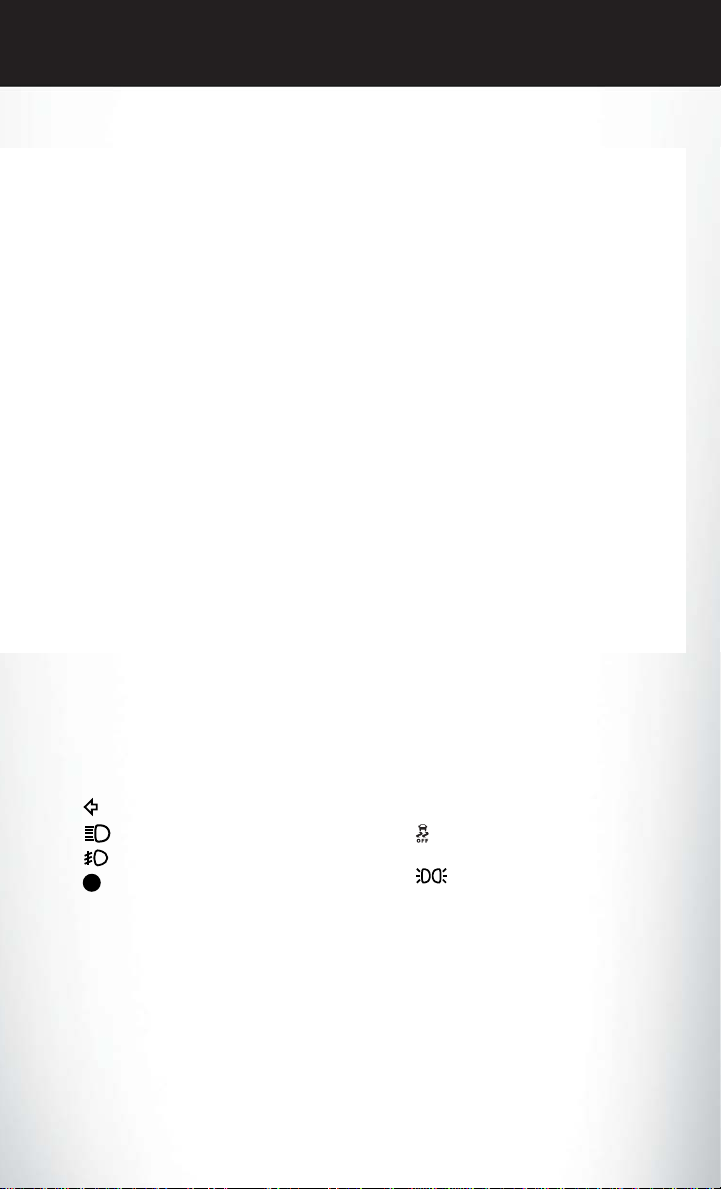
CONTROLS AT A GLANCE
5. Speedometer
6. Tachometer
7. Selected Gear
Indicators
- Turn Signal Indicators
- High Beam Indicator
- Front Fog Light Indicator
- Vehicle Security Indicator*
CRUISE
- Cruise Indicator
- Electronic Stability Control
(ESC) Off Indicator
- Park/Headlight ON Indicator
Odometer Messages
door - Door Ajar CHANgE OIL* - Change Engine Oil
dECK - Trunk Ajar gASCAP - Fuel Cap Fault
HOTOIL* - Engine Oil is over temperature LoW tirE - Low Tire Pressure
* If equipped ** Bulb Check with Key On
7

GETTING STARTED
KEY FOB
Locking And Unlocking The Doors
• Press and release the LOCK button on the
RKE transmitter to lock both doors. The
turn signal lights will flash and the horn will
chirp to acknowledge the signal.
• Press and release the UNLOCK button
on the RKE transmitter once to unlock the
driver’s door (EVIC can be setup for driver
door first, otherwise this will unlock all
doors), or press the unlock button twice
within five seconds to unlock all doors.
The turn signal lights will flash to acknowledge the unlock signal. The illuminated
entry system will also turn on.
• All doors can be programmed to unlock
on the first press of the UNLOCK button.
Refer to Programmable Features in this
guide.
Opening The Trunk
• Press the Trunk Release button on the transmitter two times within five seconds to open
the trunk.
1 — Trunk Release
2 — Unlock Door(s)
3 — Lock Door(s)
4 — Remote Start
Panic Alarm
• Press the PANIC button once to turn the panic alarm on.
• Wait approximately three seconds and press the button a second time to turn the panic
alarm off.
WARNING!
• When leaving the vehicle, always remove the Key Fob from the ignition and lock your
vehicle.
• Never leave children alone in a vehicle, or with access to an unlocked vehicle. Allowing
children to be in a vehicle unattended is dangerous for a number of reasons. A child or
others could be seriously or fatally injured. Children should be warned not to touch the
parking brake, brake pedal or the shift lever.
• Do not leave the Key Fob in the vehicle, or in a location accessible to children. A child
could operate power windows, other controls, or move the vehicle.
8
GETTING STARTED
REMOTE START
x
• Press the REMOTE START button
the REMOTE START button a third time shuts the engine off.
• To drive the vehicle, press the UNLOCK button, insert the key in the ignition and turn to the
ON/RUN position.
• With remote start, the engine will only run for 15 minutes (timeout) unless the ignition key is
placed in the ON/RUN position.
• The vehicle must be started with the key after two consecutive timeouts.
• Do not start or run an engine in a closed garage or confined area. Exhaust gas contains
Carbon Monoxide (CO) which is odorless and colorless. Carbon Monoxide is poisonous
and can cause you or others to be severely injured or killed when inhaled.
• Keep Key Fob transmitters away from children. Operation of the Remote Start System,
windows, door locks or other controls could cause you and others to be severely injured or
killed.
TRUNK LOCK AND RELEASE
• Use the Remote Keyless Entry (RKE) transmitter to open the trunk from outside the vehicle.
From inside the vehicle the trunk lid can be released by pressing the TRUNK RELEASE
button located on the instrument panel to the left of the steering wheel.
NOTE:
The shift lever must be in PARK for this button to operate.
• To unlatch the trunk lid from outside the vehicle, press and release the TRUNK button on the
RKE transmitter two times.
• With the ignition switch in the ON/RUN position, the word “dECK” will display in place of the
odometer display indicating that the trunk is open. The odometer display will reappear once
the trunk is closed or if the trip button is depressed.
• With the ignition switch in the LOCKposition or with the key out, the word “dECK” will display
until the trunk is closed.
• On EVIC-equipped vehicles, the words “Trunk Ajar” will display.
Trunk Emergency Release
• As a security measure,a Trunk Internal EmergencyRelease lever is built into the trunk latching
mechanism. In the event of an individual being locked inside the trunk, the trunk can be simply
opened by pulling on the glow-in-the-dark handle attached to the trunk latching mechanism.
2
on the Key Fob twice within five seconds. Pressing
WARNING!
WARNING!
Do not allow children to have access to the trunk, either by climbing into the trunk from
outside, or through the inside of the vehicle. Always close the trunk lid when your vehicle is
unattended. Once in thetrunk, young children may not be able to escape,even if they entered
through the rear seat. If trapped in the trunk, children can die from suffocation or heat stroke.
9

GETTING STARTED
SECURITY ALARM
To Arm:
• Lock the door using either the power door lock switch (one door must be open) or the LOCK
button on the Remote Keyless Entry (RKE) transmitter (doors can be open or closed), and
close all doors.
NOTE:
The VehicleSecurity Alarm will not arm if you lock the doors with the manual door lock plungers.
• The Vehicle Security Light in the instrument cluster will flash for 16 seconds. This shows that
the Vehicle Security Alarm is arming. During this period, if a door is opened, the ignition is
cycled to ON/RUN, or the power door locks are unlocked in any manner, the VehicleSecurity
Alarm will automatically disarm.
NOTE:
• During the 16-second arming period, if a door is opened or the ignition is cycled to ON/RUN,
the Vehicle Security Alarm will automatically disarm.
• Once armed, the Vehicle Security Alarm disables the unlock switch on the driver door trim
panel and passenger door trim panel.
To Disarm The System:
• Press the Key Fob UNLOCK button or cycle the ignition to the ON/START position.
• The Vehicle Security Alarm is designed to protect your vehicle; however, you can create
conditions where the Vehicle Security Alarm will give you a false alarm. If one of the previously
described arming sequences has occurred, the Vehicle Security Alarm will arm regardless of
whether you are in the vehicle or not. If you remain in the vehicle and open a door, the alarm
will sound. If this occurs, disarm the Vehicle Security Alarm.
• If the Vehicle Security Alarm is armed and the battery becomes disconnected the Vehicle
Security Alarm will remain armed when the battery is reconnected. The exterior lights will
flash, and the horn will sound. If this occurs, disarm the Vehicle Security Alarm.
SEAT BELT
• Be sure everyone in your vehicle is in a seat and using a seat belt properly.
• Position the lap belt across your thighs, below your abdomen. To remove slack in the lap
portion, pull up a bit on the shoulder belt. To loosen the lap belt if it is too tight, tilt the latch
plate and pullon the lap belt. A snug belt reduces the risk of sliding under the belt in a collision.
• Position the shoulder belt on your chest so that it is comfortable and not resting on your neck.
The retractor will withdraw any slack in the belt.
• A shoulder belt placed behind you will not protect you from injury during a collision. You are
more likely to hit your head in a collision if you do not wear your shoulder belt. The lap and
shoulder belt are meant to be used together.
10
GETTING STARTED
• A belt that is too loose will not protect you properly. In a sudden stop you could move too far
forward, increasing the possibility of injury. Wear your seat belt snugly.
• A frayed or torn belt could rip apart in a collision and leave you with no protection. Inspect the
belt system periodically, checking for cuts, frays, or loose parts. Damaged parts must be
replaced immediately.Do not disassemble or modify the system. Seat belt assemblies must be
replaced after a collision if they have been damaged (bent retractor, torn webbing, etc.).
• The seat belts for both front seating positions are equipped with pretensioning devices that
are designed to remove slack from the seat belt in the event of a collision.
• A deployed pretensioner or a deployed air bag must be replaced immediately.
WARNING!
In a collision, you and your passengers can suffer much greater injuries if you are not buckled
up properly. You can strike the interior of your vehicle or other passengers, or you can be
thrown out of the vehicle. Always be sure you and others in your vehicle are buckled up
properly.
SUPPLEMENTAL RESTRAINT SYSTEM (SRS) — AIR BAGS
• This vehicle has Advanced Front Air Bags for both the driver and right front passenger as a
supplement to the seat belt restraint system. The Advanced Front Air Bags will not deploy in
every type of collision.
• Advanced FrontAir Bags are designed to provide additional protection by supplementing the
seat belts in certain frontal collisions depending on several factors, including the severity and
type of collision. Advanced Front Air Bags are not expected to reduce the risk of injury in rear,
side, or rollover collisions.
• This vehicle may be equipped with Supplemental Side Air Bag Inflatable Curtains to protect
the driver, front and rear passengers sitting next to a window.
• This vehicle is equipped with Supplemental Seat-Mounted Side Air Bags to provide enhanced
protection to help protect an occupant during a side impact.
• If the Air Bag Warning Light
have the vehicle ser viced by an authorized service center immediately.
• Refer to the Owner's Manual on the DVD for further details regarding the Supplemental
Restraint System (SRS).
is not on during starting, stays on, or turns on while driving,
11
GETTING STARTED
WARNING!
• Relying on the air bags alone could lead to more severe injuries in a collision. The air bags
work with your seat belt to restrain you properly. In some collisions, the air bags won't
deploy at all. Always wear your seat belts even though you have air bags.
• Being too close to the steering wheel or instrument panel during Advanced Front Air Bag
deployment could cause serious injury, including death. Air bags need room to inflate.
Sit back, comfortably extending your arms to reach the steering wheel or instrument
panel.
•
Supplemental Side Air Bag Inflatable Curtains and Supplemental Seat-Mounted Side Air
Bags need room to inflate. Do not lean against the door or window. Sit upright in the center
of the seat.
• Being too close to the Supplemental Side Air Bag Inflatable Curtain and/or SeatMounted Side Air Bag during deployment could cause you to be severely injured or killed.
• Do not drive your vehicle after the air bags have deployed. If you are involved in another
collision, the air bags will not be in place to protect you.
• After any collision, the vehicle should be taken to an authorized dealer immediately.
CHILD RESTRAINTS
• Children 12 years or younger should ride properly buckled up in a rear seat, if available.
According to crash statistics,children are safer when properly restrained in the rear seats rather
than in the front.
• Every state in the United States and all Canadian provinces require that small children ride in
proper restraint systems. This is the law, and you can be prosecuted for ignoring it.
NOTE:
• For additional information, refer to www.seatcheck.org or call 1–866–SEATCHECK (1–866–
732–8243).
• Canadian residents, should refer to Transport Canada’s website for additional information:
http://www.tc.gc.ca/eng/roadsafety/safedrivers-childsafety-index-53.htm
LATCH — Lower Anchors And Tethers For CHildren
• Your vehicle is equipped with the child restraint anchorage system called LATCH, which
stands for Lower Anchors and Tethers for CHildren.
• The rear outboard seating positions have lower anchors and top tether anchors. The rear
center seating position has a top tether anchor only.
• You may use the LATCH anchorage system until the combined weight of the child and the
child restraint is 65 lbs (29.5 kg). Use the seat belt and tether anchor instead of the LATCH
system once the combined weight is more than 65 lbs (29.5 kg).
12

GETTING STARTED
• The lower anchorages are round bars that are found at the rear of the seat cushion where
it meets the seatback, below the anchorage symbols on the seatback. They are just visible
when you lean into the rear seat to install the child restraint. You will easily feel them if you run
your finger along the gap between the seatback and seat cushion.
In addition, there are tether strap an-
•
chorages behind each rear seating position
located in the panel between the rear seatback and the rear window. These tether
strap anchorages are under a plastic cover
with the tether anchorage symbol on it.
Do not install child restraints with rigid lower
•
attachments in the center seating position.
Only install this type of child restraint in the
outboard seating positions. Child restraints
with flexible, webbing mounted lower attachments can be installed in any rear seating
position. In the center position, the inner
anchorages are 15.4 inches (392 mm) apart.
Installing The Child Restraint Using The LATCH Lower Anchors
NOTE:
Never “share” a LATCH anchorage with two or more child restraints.
1. Loosen the adjusters on the lower straps and on the tether strap of the child seat so that you
can more easily attach the hooks or connectors to the vehicle anchorages.
2. Attach the lower hooks or connectors of the child restraint to the lower anchorages in the
selected seating position.
3. If the child restraint has a tether strap, connect it to the top tether anchorage. See below for
directions to attach a tether anchor.
4. Tighten all of the straps as you push the child restraint rearward and downward into the seat.
Remove slack in the straps according to the child restraint manufacturer’s instructions.
5. Test that the child restraint is installed tightly by pulling back and forth on the child seat at the
belt path. It should not move more than 1 inch (25.4 mm) in any direction.
13

GETTING STARTED
Installing The Child Restraint Using The Vehicle Seat Belts
• The seat belts in the passenger seating positions are equipped with a Switchable Automatic
Locking Retractor (ALR) that is designed to keep the lap portion of the seat belt tight around
the child restraint. Any seat belt system will loosen with time, so check the belt occasionally,
and pull it tight if necessary.
• Always use the tether anchor when using the seat belt to install a forward facing child restraint,
up to the recommended weight limit of the child restraint.
To Install A Child Seat Using An ALR:
1. Pull enough of the seat belt webbing from the retractor to pass it through the belt path of the
child restraint. Do not twist the belt webbing in the belt path.
2. Slide the latch plate into the buckle until you hear a “click.”
3. Pull on the webbing to make the lap portion tight against the child seat.
4. To lock the seat belt, pull down on the shoulder part of the belt until you have pulled all the seat
belt webbing out of the retractor. Then, allow the webbing to retract back into the retractor.
As the webbing retracts, you will hear a clicking sound. This means the seat belt is now in the
Automatic Locking mode.
5. Try to pullthe webbing out of the retractor. If it is locked, you should notbe able to pull out any
webbing. If the retractor is not locked, repeat the last step.
6. Finally,pull up on any extra webbing to tighten the lap portion around the child restraint while
you push the child restraint rearward and downward into the vehicle seat.
7.
If the child restraint has a top tether strap and the seating position has a top tether anchorage,
connect the tether strap to the anchorage and tighten the tether strap. See below for directions
to attach a tether anchor.
8. Test that the child restraint is installed tightly by pulling back and forth on the child seat at the
belt path. It should not move more than 1 inch (25.4 mm) in any direction.
Installing The Top Tether Strap (With Either Lower Anchors Or Vehicle Seat Belt):
• When installing a forward-facing child restraint, always secure the top tether strap, up to the
tether anchor weight limit, whether the child restraint is installed with the lower anchors or the
vehicle seat belt.
1. Rotate or lift the cover to access the anchor directly behind the seat where you are placing the
child restraint.
2. Route the tether strap to provide the most direct path for the strap between the anchor and
the child seat.
14

GETTING STARTED
3. If your vehicle is equipped with adjustable rear head restraints, raise the head restraint, and
where possible, route the tether strap under the head restraint and between the two posts.
If not possible, lower the head restraint and pass the tether strap around the outboard side of
the head restraint.
4. Attach the tether strap hook of the child restraint to the top tether anchorage and remove
slack in the tether strap according to the child restraint manufacturer’s instructions.
WARNING!
• In a collision, an unrestrained child, even a tiny baby, can become a projectile inside the
vehicle. The force required to hold even an infant on your lap could become so great that
you could not hold the child, no matter how strong you are. The child and others could be
severely injured or killed. Any child riding in your vehicle should be in a proper restraint for
the child's size.
• Rearward-facing child seats must never be used in the front seat of a vehicle with a front
passenger air bag. An air bag deployment could cause severe injury or death to infants in
this position.
• Only use a rearward-facing child restraint in a vehicle with a rear seat.
• Improper installation of a child restraint to the LATCHanchoragescan lead to failureof an
infant or child restraint. The child could be severely injured or killed. Follow the manufacturer’s directions exactly when installing an infant or child restraint.
• An incorrectly anchored tether strap could lead to increased head motion and possible
injury to the child. Use only the anchor positions directly behind the child seat to secure a
child restraint top tether strap.
• If your vehicleis equipped with asplit rear seat, make sure the tether strap does not slip into
the opening between the seatbacks as you remove slack in the strap.
FRONT SEATS
Power Seat
• The power seat switch, located on the outboard side of the seat near thefloor,controls
forward/back, up/down, and tilt adjustment.
• The recline switch controls the seatback
recliner.
15
GETTING STARTED
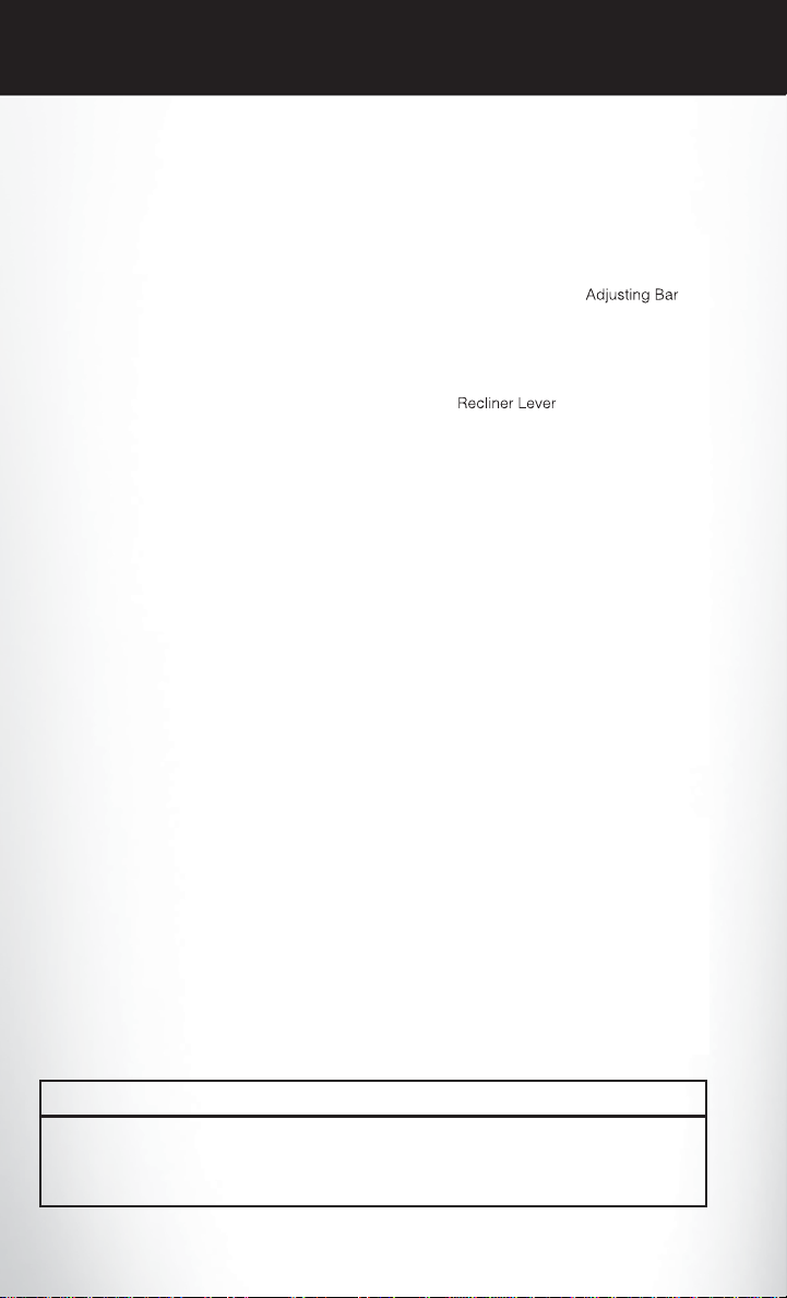
Manual Seat Adjustment
Forward/Rearward
• Lift up on the adjusting bar located at the
front of the seat near the floor and release it
when the seat is at the desired position.
Then, using body pressure, move forward
and backward on the seat to be sure that the
seat adjusters have latched.
Recliner
• Lift the recliner lever located on the outboard side of the seat, lean back and release
at the desired position.
Lumbar Support
• The lumbar adjust lever is on the outboard
side of the seatback. Rotate the lumbar
adjust lever downward to increase the lumbar support or upward to decrease the lumbar support as desired.
Driver’s Seat Height Adjustment
• The height adjustment control lever is located on the outboard side of the seat. Raise
the lever to raise the seat. Lower the lever to
lower the seat.
CAUTION!
Do not place any article under a power seat or impede its ability to move as it may cause
damage to the seat controls. Seat travel may become limited if movement is stopped by an
obstruction in the seat’s path.
16

GETTING STARTED
WARNING!
• Adjusting a seat while the vehicle is moving is dangerous. The sudden movement of the
seat could cause you to lose control. Theseat belt might notbe properly adjusted, and you
could be severely injured or killed. Only adjust a seat while the vehicle is parked.
• Do not ride with the seatback reclined so that the seat belt is no longer resting against your
chest. In a collision, you could slide under the seat belt and be severely injured or killed.
Use the recliner only when the vehicle is parked.
REAR SEATS
Folding Rear Seatback
•
To fold the rear seatback forward, pull on the
loops to fold down either or both seatbacks.
When returning the rear seatback to the upright position, be sure the seatback is latched.
HEATED SEATS
Front Heated Seats
• The controls for the front heated seats are
located in the center console above the
climate controls.
• Press the switch once to select High-level
heating. Press the switch a second time to
select Low-level heating. Press the switch a
third time to shut the heating elements Off.
• If the High-level setting is selected, the system will automatically switch to Low-level
after approximately 30 minutes. The Lowlevel setting will turn Off automatically after
approximately 30 minutes.
17
GETTING STARTED
WARNING!
• Persons who are unable to feel pain to the skin because of advanced age, chronic illness,
diabetes, spinal cord injury, medication, alcohol use, exhaustion or other physical conditions must exercise care when using the seat heater. It may cause burns even at low
temperatures, especially if used for long periods of time.
• Do not place anything on the seat that insulates against heat, such as a blanket or cushion.
This may cause the seat heater to overheat. Sitting in a seat that has been overheated
could cause serious burns due to the increased surface temperature of the seat.
TILT/TELESCOPING STEERING COLUMN
• The tilt/telescoping control lever is located
below the steering wheel at the end of the
steering column.
• Push down on the lever to unlock the steering column.
• To tilt the steering column, move the steering wheel upward or downward as desired.
• To lengthen or shorten the steering column,
pull the steering wheel outward or push it
inward as desired.
• Pull upward on the lever to lock the column
firmly in place.
WARNING!
Do not adjust the steering wheel while driving. The tilt/telescoping adjustment must be
locked while driving. Adjusting the steering wheel while driving or driving without the
tilt/telescoping adjustment locked could cause the driver to lose control of the vehicle. Failure
to follow this warning may result in you and others being severely injured or killed.
18

OPERATING YOUR VEHICLE
ENGINE BREAK-IN RECOMMENDATIONS
• A long break-in period is not required for the engine and drivetrain (transmission and axle) in
your vehicle.
• Drive moderately during the first 300 miles (500 km). After the initial 60 miles (100 km),
speeds up to 50 or 55 mph (80 or 90 km/h) are desirable.
• While cruising, brief full-throttle acceleration within the limits of local traffic laws contributes
to a good break-in. Wide-open throttle acceleration in low gear can be detrimental and should
be avoided.
• The engine oil installed in the engine at the factory is a high-quality energy conserving type
lubricant. Oil changes should be consistent with anticipated climate conditions under which
vehicle operations will occur. For the recommended viscosity and quality grades, refer to
“Maintaining Your Vehicle.”
NOTE:
A new engine may consume some oil during its first few thousand miles (kilometers) of operation.
This should be considered a normal part of the break-in and not interpreted as an indication of an
engine problem or malfunction.
CAUTION!
Never use Non-Detergent Oil or Straight Mineral Oil in the engine or damage may result.
19
OPERATING YOUR VEHICLE
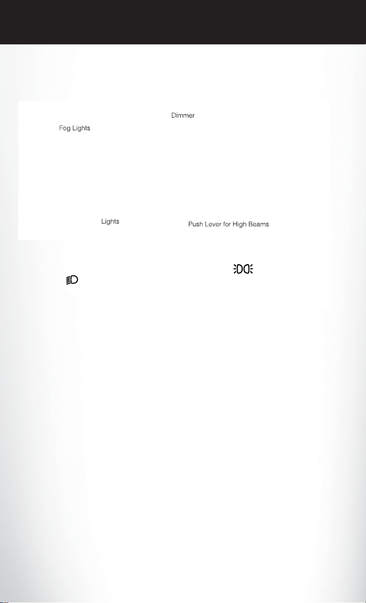
TURN SIGNAL /LIGHTS LEVER
Headlights/Parking Lights/Automatic Headlights
• Rotate the end of the lever to the first detent for parking lights , the second detent for
headlights
• When set to AUTO,the system automatically turns the headlights on or off based on ambient
light levels.
Instrument Panel Dimmer
• Rotate the center portion of the lever to the extreme bottom position to fully dim the
instrument panel lights and prevent the interior lights from illuminating when a door is opened.
• Rotate the center portion of the lever up to increase the brightness of the instrument panel
lights when the parking lights or headlights are on.
• Rotate the center portion of the lever upward to the next detent position to brighten the
odometer and radio controls when the parking lights or headlights are on.
• Rotate the center portion of the lever upwardto the last detent to turn on the interior lighting.
, and the third detent for AUTO.
Flash To Pass
• Pull the lever toward you to activate the high beams. The high beams will remain on until the
lever is released.
High Beam Operation
• Push the lever forward to activate the high beams.
NOTE:
For safe driving, turn off the high beams when oncoming traffic is present to prevent headlight
glare and as a courtesy to other motorists.
20

OPERATING YOUR VEHICLE
Front Fog Lights
• The front fog light switch is on the multifunction lever. To activate the front fog lights, turn on
the parking lights or the low beam headlights and pull out the end of the multifunction lever.
Turn Signals/Lane Change Assist
• Tap the lever up or down once and the turn signal (right or left) will flash three times and
automatically turn off.
WIPER/WASHER LEVER
Front Wipers
Intermittent, Low And High Operation
• Rotate the end of the lever to the first detent position for one of five intermittent settings, the
second for low wiper operation and the third detent for high wiper operation.
Mist
• Pull down on the lever and release when a single wipe is desired.
NOTE:
The mist featuredoes not activatethe washer pump; therefore,no washer fluid will be sprayed on
the windshield. The wash function must be activated in order to spray the windshield with washer
fluid.
Washer Operation
• Pull the lever toward you and hold for as long as spray is desired.
21
OPERATING YOUR VEHICLE
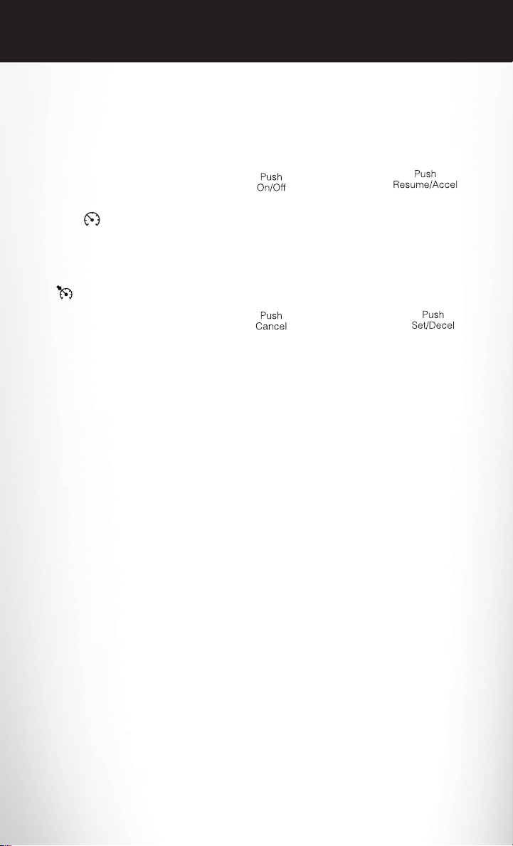
SPEED CONTROL
• The Speed Control switches are located on the steering wheel.
Cruise ON/OFF
• Push the ON/OFF button to activate the
Speed Control.
• CRUISE
cluster to indicate the Speed Control is on.
• Push the ON/OFF button a second time to
turn the system off.
SET
•
With the Speed Control on, push and release
the SET – button to set a desired speed.
Accel/Decel
To Increase Speed
• When the Electronic Speed Control is set, you can increase speed by pushing the RES +
button.
• The speed increment shown is dependant on the speed of U.S. (mph) or Metric (km/h) units:
U.S. Speed (mph)
• Pressing the RES + button once will result in a 1 mph increase in set speed. Each subsequent
tap of the button results in an increase of 1 mph.
• If the button is continually pressed, the set speed will continue to increase until the button is
released, then the new set speed will be established.
Metric Speed (km/h)
• Pressing the RES + button once will result in a 2 km/h increase in set speed. Each subsequent
tap of the button results in an increase of 2 km/h.
• If the button is continually pressed, the set speed will continue to increase until the button is
released, then the new set speed will be established.
will appear on the instrument
22
OPERATING YOUR VEHICLE
To Decrease Speed
• When the Electronic Speed Control is set, you can decrease speed by pushing the SET -
button.
• The speed decrement shown is dependant on the speed of U.S. (mph) or Metric (km/h) units:
U.S. Speed (mph)
• Pressing the SET - button once will result in a 1 mph decrease in set speed. Eachsubsequent
tap of the button results in a decrease of 1 mph.
• If the button is continually pressed, the set speed will continue to decrease until the button
is released, then the new set speed will be established.
Metric Speed (km/h)
• Pressing the SET -button once will resultin a 2 km/hdecrease in set speed.Eachsubsequent
tap of the button results in a decrease of 2 km/h.
• If the button is continually pressed, the set speed will continue to decrease until the button
is released, then the new set speed will be established.
Resume
• To resume a previously selected set speed in memory, push the RES + button and release.
Cancel
• Push the CANCEL button, or apply the brakes to cancel the set speed and maintain the set
speed memory.
• Push the ON/OFF button to turn the system off and erase the set speed memory.
WARNING!
• Leaving the Electronic Speed Control system on when not in use is dangerous. You could
accidentally set the system or cause it to go faster than you want. You could lose control
and have a collision. Always leave the Electronic Speed Control system off when you are
not using it.
• Electronic Speed Control can be dangerous where the system cannot maintain a constant
speed. Your vehicle could go too fast for the conditions, and you could lose control.
A collision could be the result. Do not use Electronic Speed Control in heavy traffic or on
roads that are winding, icy, snow-covered or slippery.
23
OPERATING YOUR VEHICLE
MANUAL CLIMATE CONTROLS
Air Recirculation
• Use Recirculation for maximum A/C operation.
• For window defogging, turn the Recirculation button off.
• Recirculation is allowed in floor and defrost/floor (mix modes) for approximately five minutes.
Heated Mirrors
• The mirrors are heated to melt frost or ice. This feature is activated whenever you turn on the
rear window defroster.
24
OPERATING YOUR VEHICLE
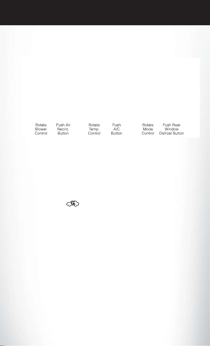
AUTOMATIC TEMPERATURE CONTROLS (ATC)
Automatic Operation
• Turn the Mode and Blower Controls to the AUTO position.
• Select the desired temperature by rotating the Temperature Control.
• The system will maintain the set temperature automatically.
Air Conditioning (A/C )
• If the air conditioning button is pressed while in the AUTOmode, the indicator light may flash
three times to indicate the cabin air is being controlled automatically.
Air Recirculation
• Use Recirculation for maximum A/C operation.
• For window defogging, turn the Recirculation button off.
• If the Recirculation button is pressed while in the AUTO mode, the indicator light may flash
three times to indicate the cabin air is being controlled automatically.
Heated Mirrors
• The mirrors are heated to melt frost or ice. This feature is activated whenever you turn on the
rear window defroster.
25

OPERATING YOUR VEHICLE
POWER SUNROOF
• The power sunroof switch is located on the
overhead console.
Opening Sunroof
Express Open
• Press the switch rearward and release it
within one-half second. The sunroof will
fully open and stop automatically.
Manual Open
• Press and hold the switch rearward to open
the sunroof. Any release of the switch will
stop the movement, and the sunroof will
remain in a partially open position until the
switch is pressed again.
Venting Sunroof
• Press and releasethe button and thesunroof
will open to the vent position. This is called
“Express Vent” and will occur regardless of
sunroof position. During Express Vent operation, any movement of the switch will stop the
sunroof.
1 — Opening Sunroof
2 — Venting Sunroof
3 — Closing Sunroof
Closing Sunroof
Express Closing
• Press the switch forward and release it within one-half second. The sunroof will fully close
automatically from any position.
Manual Closing
• Press and hold the switch forward to close the sunroof. Any release of the switch will stop the
movement, and the sunroof will remain in a partially closed position until the switch is pressed
again.
26
OPERATING YOUR VEHICLE
Pinch Protection Feature
• This feature will detect an obstruction in the opening of the sunroof during Express Close
operation. If an obstruction in the path of the sunroof is detected, the sunroof will automatically retract. Remove the obstruction if this occurs. Next, press the switch forward and release
to Express Close.
NOTE:
If three consecutive sunroof close attempts result in Pinch Protect reversals, the fourth close
attempt will be a Manual Close movement with Pinch Protect disabled.
WARNING!
• Never leave children alone in a vehicle, or with access to an unlocked vehicle. Never leave
the Key Fob in or near the vehicle, or in a location accessible to children. Occupants,
particularly unattended children, can become entrapped by the power sunroof while
operating the power sunroof switch. Such entrapmentmay result in serious injury or death.
• In a collision, there is a greater risk of being thrown from a vehicle with an open sunroof.
You could also be severely injured or killed. Alwaysfasten your seat belt properly and make
sure all passengers are properly secured.
• Do not allow small children to operate the sunroof. Never allow your fingers, other body
parts, or any object to project through the sunroof opening. Injury may result.
WIND BUFFETING
• Wind buffeting can be described as a helicopter-type percussion sound. If buffeting occurs
with the rear windows open, adjust the front and rear windows together.
• If buffeting occurs with the sunroof open, adjust the sunroof opening, or ad just any window.
This will minimize buffeting.
27

ELECTRONICS
YOUR VEHICLE'S SOUND SYSTEM
1. Uconnect® Voice Command Button pg. 64
2. Uconnect® Phone Button pg. 61
3. Steering Wheel Audio Controls (Left) pg. 59
4. Steering Wheel Audio Controls (Right) pg. 59
28
Loading...