


Imperial 1959
CONTENTS
General Specifications 1
Section I—Suspension 4
Section II—Axle—Rear 16
Section III—Brakes 17
Section IV—Accessory Belt Drives 23
Section V—Cooling System 26
Section VI—Electrical System 27
Section VII—Engine 41
Section VIII—Fuel and Exhaust System 70
Section IX—Frame 74
Section X—Steering 76
Section XI—Transmission 80
Section XII—Universal Joints and Propeller Shaft 83
Section XIII—Wheels and Tires 84
Section XIV—Body and Sheet Metal—Town and Country Models 85
Section XV—Lubrication 88
Section XVI—Radio and Heater 88
Section XVII—Heater—Air Conditioning 97
MyMopar.com
CHRYSLER SERVICE MANUAL
SERVICING THE 1959 CHRYSLER AND IMPERIAL
GENERAL SPECIFICATIONS—1
This supplement contains advanced service information
on
perial Models. Only changes and improvements affecting
are included.
procedures will remain the same as those
If
the information desired cannot
be
found
for
corresponding models covered
Chrysler and Imperial Service Manual D-16350.
In order
Service Manual D-l 6350, the corresponding
The supersedence
The service tools referred
Company, 17640 Grand River, Detroit 27, Michigan,
Extra copies
Order from Chrysler Division, P.O.
to
use this supplement to best advantage with
or
of
these models is as follows:
Chrysler Models:
Windsor
Saratoga
New Yorker
Imperial Models
Custom,
and LeBaron
of
this Supplement
Crown,
to in
this manual are available through the Miller Manufacturing
are
available at $2.00 each, under part number D-l6798.
Box
1958
LC-1
LC-2
LC-3
1958
LY-1
1658, Detroit 31, Michigan.
the
superseding car models must be understood.
U.S.A.,
the new 1959 Chrysler^ and Im-
the
servicing
in
this supplement
of the new
the
models
servicing
in the 1958
previous Chrysler and Imperial
1959
MC-1
MC-2
MC-3
1959
MY-1
unless otherwise specified.
CHRYSLER DIVISION
Chrysler Corporation
DETROIT 31, MICHIGAN
Chrysler Corporation reserves
ments
in its
manufactured.
D-l 6798 12M-SD & TO-10-58
product without imposing
the
right
to
make changes
any
obligations upon itself
in
design
to
or to
make additions
install them
on its
products previously
to or
LITHO
improve-
IN
U.S.A.
MyMopar.com
2—GENERAL SPECIFICATIONS
CHRYSLER SERVICE MANUAL
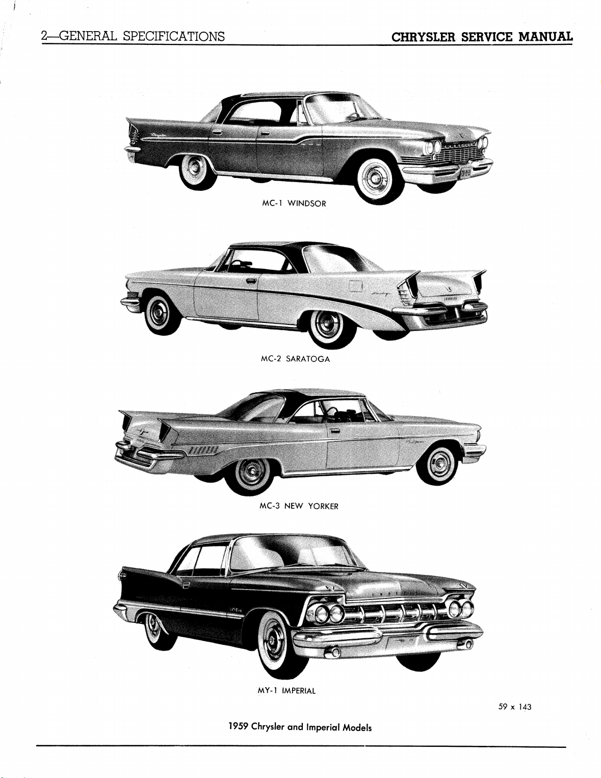
MC-l WINDSOR
MC-2 SARATOGA
MC-3 NEW YORKER
MY-1 fMPERiAL
1959 Chrysler and Imperial Models
59 x 143
MyMopar.com
CHRYSLER SERVICE MANUAL
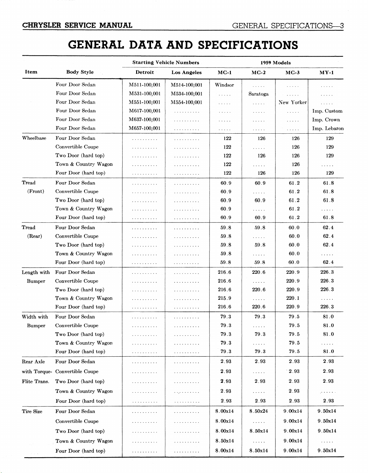
GENERAL DATA AND SPECIFICATIONS
GENERAL SPECIFICATIONS—3
Item Body Style
Four Door Sedan
Four Door Sedan
Four Door Sedan
Four Door Sedan
Four Door Sedan
Four Door Sedan
Wheelbase Four Door Sedan
Convertible Coupe
Two Door (hard top)
Town & Country Wagon
Four Door (hard top)
Tread Four Door Sedan
(Front) Convertible Coupe
Two Door (hard top)
Town & Country Wagon
Four Door (hard top)
Tread Four Door Sedan
(Rear) Convertible Coupe
Two Door (hard top)
Town & Country Wagon
Four Door (hard top)
Length with Four Door Sedan
Bumper Convertible Coupe
Two Door (hard top)
Town & Country Wagon
Four Door (hard top)
Width with Four Door Sedan
Bumper Convertible Coupe
Two Door (hard top)
Town & Country Wagon
Four Door (hard top)
Rear Axle Four Door Sedan
with Torque- Convertible Coupe
Flite Trans. Two Door (hard top)
Town & Country Wagon
Four Door (hard top)
Tire Size Four Door Sedan
Convertible Coupe
Two Door (hard top)
Town & Country Wagon
Four Door (hard top)
Starting Vehicle Numbers
Detroit
M511-100,001
M531-100,001
M551-100,001
M617-100,001
M637-100,001
M657-100,001
Los Angeles
M514-100,001
M534-100,001
M554-100,001
MC-1
Windsor
122
122
122
122
122
60.9
60.9
60.9
60.9
60.9
59.8
59.8
59.8
59.8
59.8
216.6
216.6
216.6
215.9
216.6
79.3
79.3
79.3
79.3
79.3
2.93
2.93
2.93
2.93
2.93
8.00x14
8.00x14
8.00x14
8.50x14
8.00x14
1959 Models
MC-2
Saratoga
126
126
126
60.9
60.9
60.9
59.8
59.8
59.8
220.6
220.6
220.6
79.3
79.3
79.3
2.93
2.93
2.93
8.50x24
8.50x14
8.50x14
MC-3
New Yorker
126
126
126
126
126
61.2
61.2
61.2
61.2
61.2
60.0
60.0
60.0
60.0
60.0
220.9
220.9
220.9
220.1
220.9
79.5
79.5
79.5
79.5
79.5
2.93
2.93
2.93
2.93
2.93
9.00x14
9.00x14
9.00x14
9.00x14
9.00x14
MyMopar.com
MY-1
Imp.
Imp.
Imp.
9.50x14
9.50x14
9.50x14
9.50x14
Custom
Crown
Lebaron
129
129
129
129
61.8
61.8
61.8
61.8
62.4
62.4
62.4
62.4
226.3
226.3
226.3
226.3
81.0
81.0
81.0
81.0
2.93
2.93
2.93
2.93
4—SUSPENSION
CHRYSLER SERVICE MANUAL
Section I
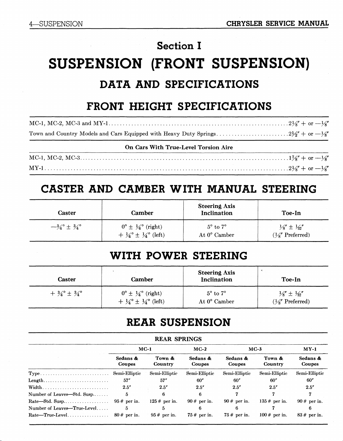
SUSPENSION (FRONT SUSPENSION)
DATA AND SPECIFICATIONS
FRONT HEIGHT SPECIFICATIONS
MC-1,
MC-2, MC-3 and MY-1
Town and Country Models and Cars Equipped with Heavy Duty Springs
On Gars With True-Level Torsion Aire
MC-1,
MC-2,
MY-1
CASTER AND CAMBER WITH MANUAL STEERING
MC-3..
.iyg"+or
•
2Vs"+0T
Caster
~H° ± H°
Caster Camber
Type
Length
Width
Number of Leaves—Std. Susp
Rate—Std. Susp
Number of Leaves—True-Level. . .
Rate—True-Level
Steering Axis
Camber
0° ± M° (right)
+ H° ± H° (left)
Inclination
5° to 7°
At 0° Camber
(Vs"
WITH POWER STEERING
Steering Axis
Inclination
0°± M° (right)
Ji°.± M°(left)
5° to 7°
At 0° Camber
REAR SUSPENSION
REAR SPRINGS
MC-1
Sedans &
Coupes
Semi-Elliptic Semi-Elliptic Semi-Elliptic Semi-Elliptic Semi-Elliptic
57"
2.5"
5
95
# per in.
5
80 # per in.
Town &
Country
57"
2.5"
125
# per in.
95
# per in.
6
5
MC-2
Sedans &
Coupes
60"
2.5"
6
90
# per in.
6
75
# per in.
Sedans &
Coupes
60"
2.5"
7
90
# per in.
6
75
# per in.
MC-3
Town &
Country
60"
2.5"
135
# per in.
100
# per in.
7
7
Toe-In
y%
± w
Preferred)
Toe-In
± W
Preferred)
Semi-Elliptic
90
83
MY-1
Sedans &
Coupes
60"
2.5"
7
# per in.
6
# per in.
MyMopar.com
CHRYSLER SERVICE
MANUAL
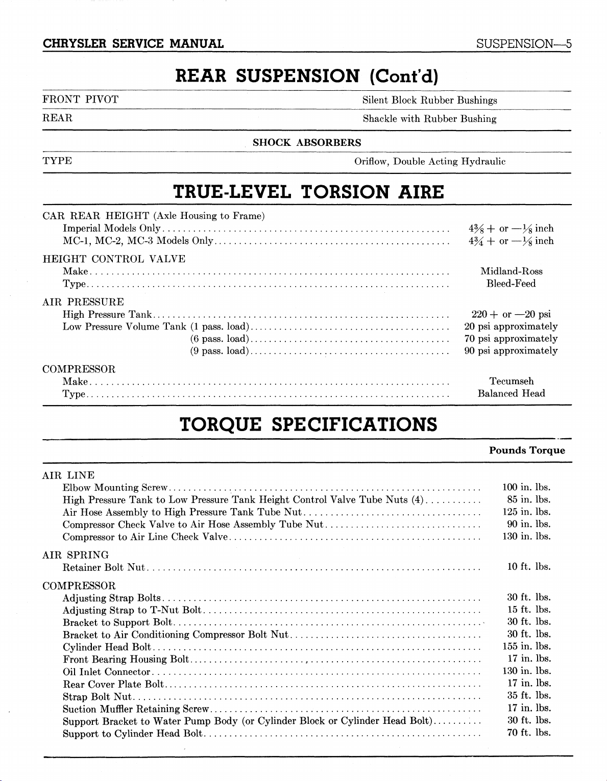
REAR SUSPENSION (Cont'd)
SUSPENSION—5
FRONT PIVOT
REAR
SHOCK ABSORBERS
TYPE
Silent Block Rubber'
Shackle with Rubber
Oriflow, Double Acting
Bushings
Bushing
Hydraulic
TRUE-LEVEL TORSION AIRE
CAR REAR HEIGHT (Axle Housing
Imperial Models Only
MC-1,
MC-2, MC-3 Models Only 4%
HEIGHT CONTROL VALVE
Make Midland-Ross
Type Bleed-Feed
AIR PRESSURE
High Pressure Tank 220
Low Pressure Volume Tank
COMPRESSOR
Make Tecumseh
Type Balanced Head
4% + or
to
Frame)
(1
pass, load)
(6 pass, load) 70
(9 pass, load)
20 psi
90 psi
+ or — y% inch
+ or
approximately
psi
approximately
approximately
—y% inch
—20
psi
TORQUE SPECIFICATIONS
AIR LINE
Elbow Mounting Screw 100
High Pressure Tank
Air Hose Assembly
Compressor Check Valve
Compressor
AIR SPRING
Retainer Bolt
COMPRESSOR
Adjusting Strap Bolts
Adjusting Strap
Bracket
Bracket
Cylinder Head Bolt 155
Front Bearing Housing Bolt
Oil Inlet Connector 130
Rear Cover Plate Bolt
Strap Bolt
Suction Muffler Retaining Screw
Support Bracket
Support
to Air
to
Support Bolt
to Air
Nut 35 ft. lbs.
to
Cylinder Head Bolt 70
to
Low Pressure Tank Height Control Valve Tube Nuts
to
High Pressure Tank Tube
to Air
Line Check Valve 130
Nut
10
30 ft. lbs.
to
T-Nut Bolt 15
30 ft. lbs.
Conditioning Compressor Bolt
17 in. lbs.
to
Water Pump Body
Hose Assembly Tube
f
17 in. lbs.
(or
Nut
125
Nut 90 in. lbs.
Nut 30 ft. lbs.
17 in. lbs.
Cylinder Block
or
Cylinder Head Bolt) 30
(4) 85 in. lbs.
Pounds Torque
in. lbs.
in. lbs.
in. lbs.
ft. lbs.
ft. lbs.
in. lbs.
in. lbs.
ft. lbs.
ft. lbs.
MyMopar.com
6—SUSPENSION
CHRYSLER SERVICE MANUAL
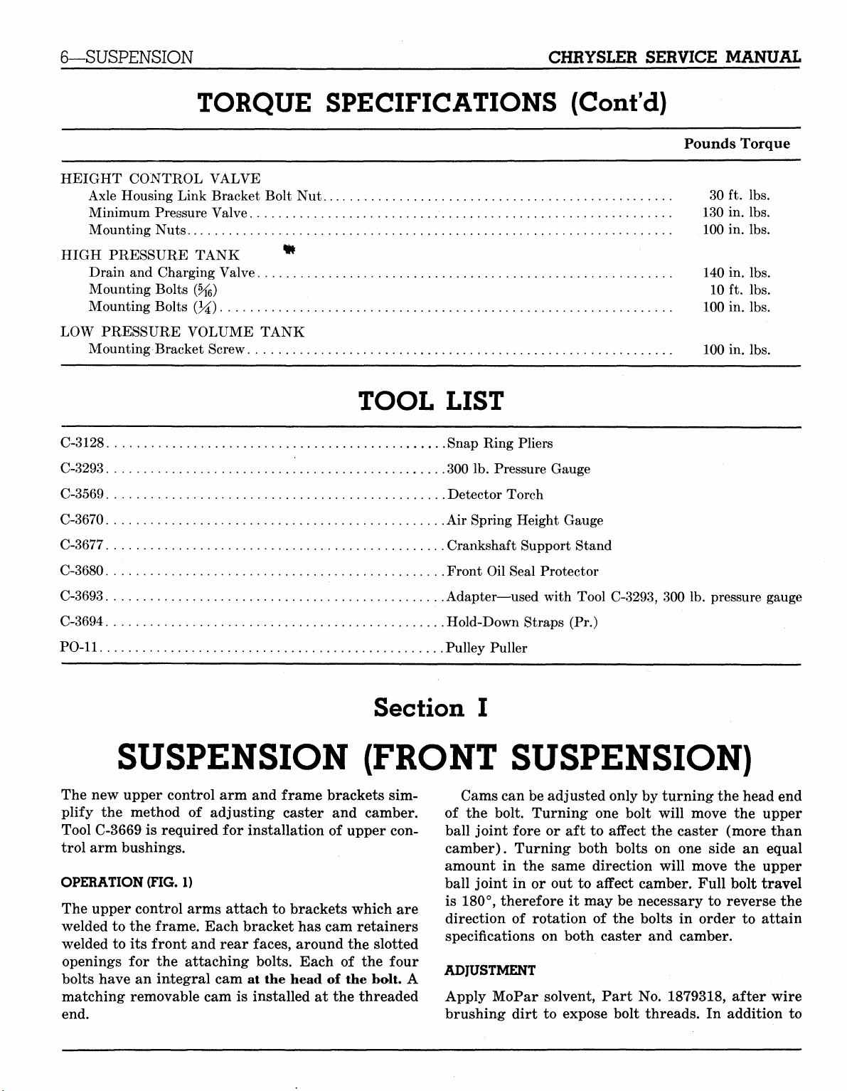
TORQUE SPECIFICATIONS (Cont'd)
HEIGHT CONTROL VALVE
Axle Housing Link Bracket Bolt
Minimum Pressure Valve 130
Mounting Nuts 100
Nut 30 ft. lbs.
Pounds Torque
in. lbs.
in. lbs.
HIGH PRESSURE TANK
Drain
and
Charging Valve 140 in.
Mounting Bolts (%>) 10
Mounting Bolts
LOW PRESSURE VOLUME TANK
Mounting Bracket Screw 100
(%)
*
100
TOOL LIST
C-3128 Snap Ring Pliers
C-3293 300
C-3569 Detector Torch
C-3670
C-3677 Crankshaft Support Stand
C-3680 Front
C-3693 Adapter—used with Tool C-3293,
C-3694 Hold-Down Straps
PO-11 Pulley Puller
Air
lb.
Pressure Gauge
Spring Height Gauge
Oil
Seal Protector
(Pr.)
300 lb.
lbs.
ft. lbs.
in. lbs.
in. lbs.
pressure gauge
SUSPENSION (FRONT SUSPENSION)
The
new
upper control
plify
the
method
Tool C-3669
trol arm bushings.
OPERATION (FIG.
The upper control arms attach
welded
welded
openings
bolts have
matching removable cam
end.
is
required
to the
to its
frame. Each bracket has cam retainers
front and rear faces, around
for the
an
integral
arm and
of
adjusting caster
for
installation
1)
attaching bolts. Each
cam at the
is
installed
frame brackets
and
of
upper con-
to
brackets which
the
of the
head
of the
at the
Section
sim-
camber.
are
slotted
four
bolt.
A
threaded
I
Cams can be adjusted only
of
the
bolt. Turning
ball joint fore
camber). Turning both bolts
amount
ball joint
is 180°, therefore
direction
specifications
ADJUSTMENT
Apply MoPar solvent, Part
brushing dirt
in the
or aft to
in or out to
of
rotation
on
to
one
bolt will move
affect
same direction will move
affect camber. Full bolt travel
it
may
be
necessary
of the
both caster
expose bolt threads.
bolts
No.
by
turning the head
the
the
caster (more than
on one
and
side
an
the
to
reverse
in
order
camber.
1879318, after wire
In
addition
to
MyMopar.com
end
upper
equal
upper
the
attain
to
CHRYSLER SERVICE MANUAL
SUSPENSION—7
RONT ADJUSTING JOLT
59x120 *&' .•- mmi
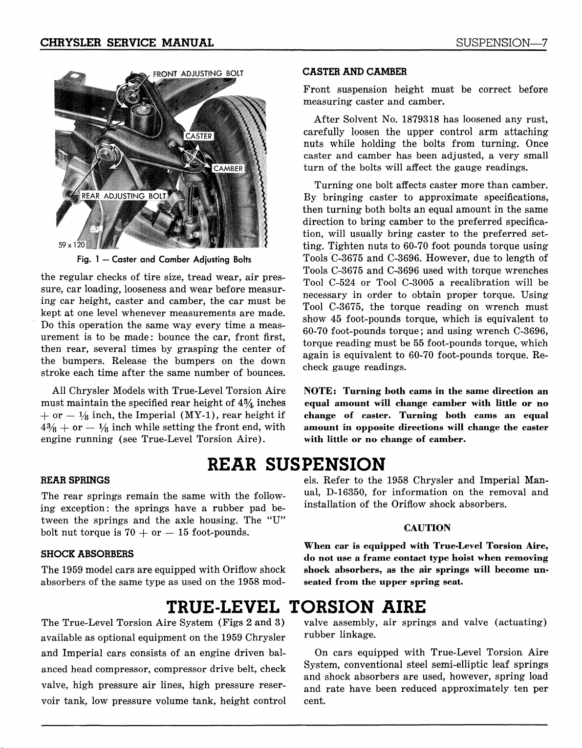
Fig.
1 — Caster and Camber Adjusting Bolts
the regular checks of tire size, tread wear, air pressure,
car loading, looseness and wear before measuring car height, caster and camber, the car must be
kept at one level whenever measurements are made.
Do this operation the same way every time a measurement is to be made: bounce the car, front first,
then rear, several times by grasping the center of
the bumpers. Release the bumpers on the down
stroke each time after the same number of bounces.
CASTER AND CAMBER
Front suspension height must be correct before
measuring caster and camber.
After Solvent No. 1879318 has loosened any rust,
carefully loosen the upper control arm attaching
nuts while holding the bolts from turning. Once
caster and camber has been adjusted, a very small
turn of the bolts will affect the gauge readings.
Turning one bolt affects caster more than camber.
By bringing caster to approximate specifications,
then turning both bolts an equal amount in the same
direction to bring camber to the preferred specification, will usually bring caster to the preferred setting. Tighten nuts to 60-70 foot pounds torque using
Tools C-3675 and C-3696. However, due to length of
Tools C-3675 and C-3696 used with torque wrenches
Tool C-524 or Tool C-3005 a recalibration will be
necessary in order to obtain proper torque. Using
Tool C-3675, the torque reading on wrench must
show 45 foot-pounds torque, which is equivalent to
60-70 foot-pounds torque; and using wrench C-3696,
torque reading must be 55 foot-pounds torque, which
again is equivalent to 60-70 foot-pounds torque. Recheck gauge readings.
All Chrysler Models with True-Level Torsion Aire
must maintain the specified rear height of 4% inches
-f or — i/8 inch, the Imperial (MY-1), rear height if
4%
+ or — % inch while setting the front end, with
engine running (see True-Level Torsion Aire).
REAR SUSPENSION
REAR SPRINGS
The rear springs remain the same with the following exception: the springs have a rubber pad between the springs and the axle housing. The "U"
bolt nut torque is 70 + or — 15 foot-pounds.
SHOCK ABSORBERS
The 1959 model cars are equipped with Oriflow shock
absorbers of the same type as used on the 1958 mod-
TRUE-LEVEL TORSION AIRE
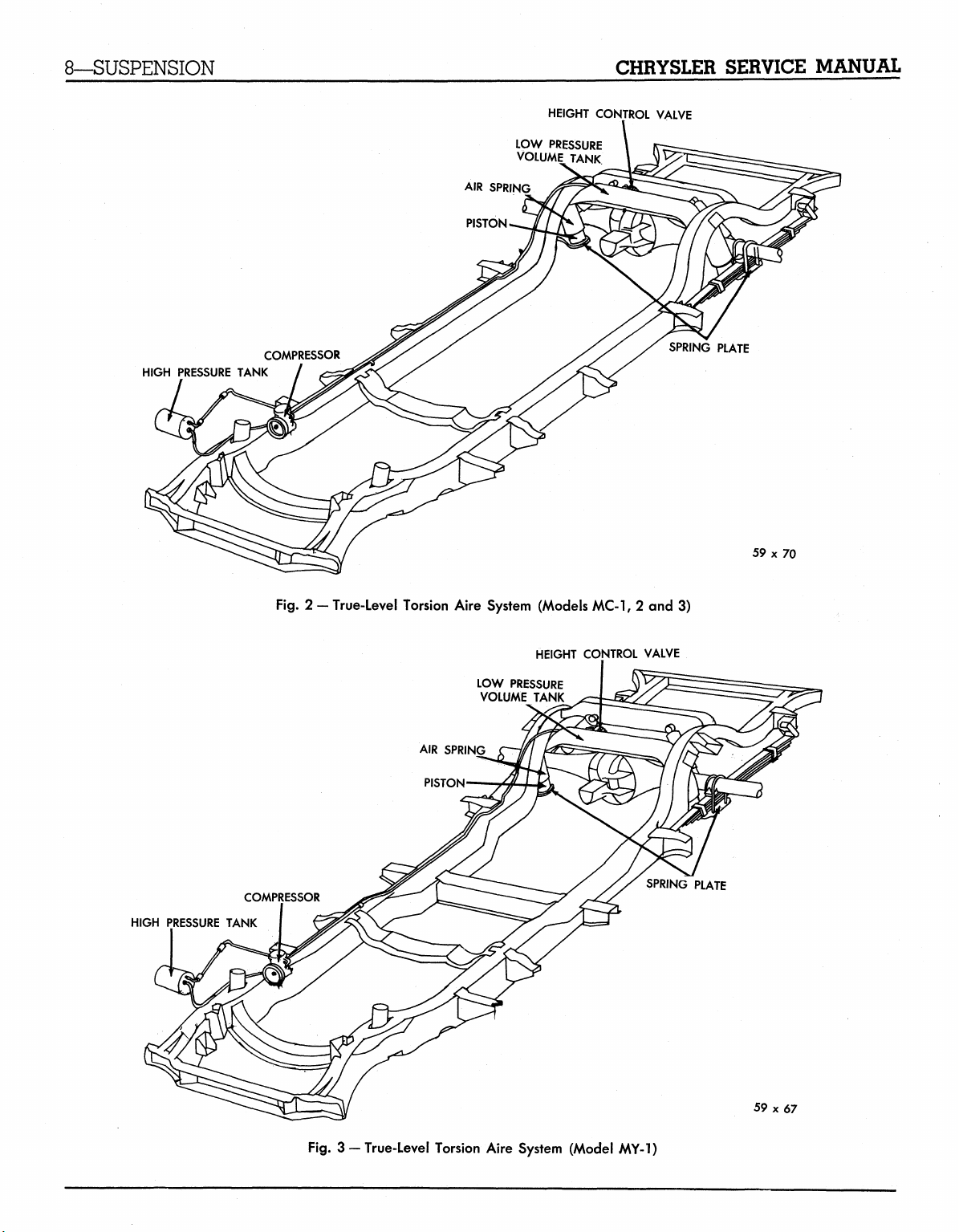
The True-Level Torsion Aire System (Figs 2 and 3)
available as optional equipment on the 1959 Chrysler
and Imperial cars consists of an engine driven bal-
anced head compressor, compressor drive belt, check
valve, high pressure air lines, high pressure reser-
voir tank, low pressure volume tank, height control
NOTE;
equal amount will change camber with little or no
change of caster. Turning both cams an equal
amount in opposite directions will change the caster
with little or no change of camber.
els.
ual,
Turning both cams in the same direction an
Refer to the 1958 Chrysler and Imperial Man-
D-16350, for information on the removal and
installation of the Oriflow shock absorbers.
CAUTION
When car is equipped with True-Level Torsion Aire,
do not use a frame contact type hoist when removing
shock absorbers, as the air springs will become unseated from the upper spring seat.
valve assembly, air springs and valve (actuating)
rubber linkage.
On cars equipped with True-Level Torsion, Aire
System, conventional steel semi-elliptic leaf springs
and shock absorbers are used, however, spring load
and rate have been reduced approximately ten per
cent.
MyMopar.com
8—SUSPENSION
CHRYSLER SERVICE MANUAL
HEIGHT CONTROL VALVE
LOW PRESSURE
VOLUME TANK
AIR SPRING
PISTON.
HIGH PRESSURE TANK
COMPRESSOR
Fig.
2 - True-Level Torsion Aire System (Models MC-1, 2 and 3)
HEIGHT CONTROL VALVE
LOW PRESSURE
VOLUME TANK
SPRING PLATE
59 x 70
HIGH PRESSURE TANK
COMPRESSOR
Fig.
3 —True-Level Torsion Aire System (Model MY-1)
SPRING PLATE
59x67
MyMopar.com
CHRYSLER SERVICE MANUAL
SUSPENSION—9
CHECK VALVE
PRESSURE LINE
SUCTION MUFFLER
59x75
OIL INLET LINE
CONNECTION
CYLINDER HEAD
VALVE PLATE
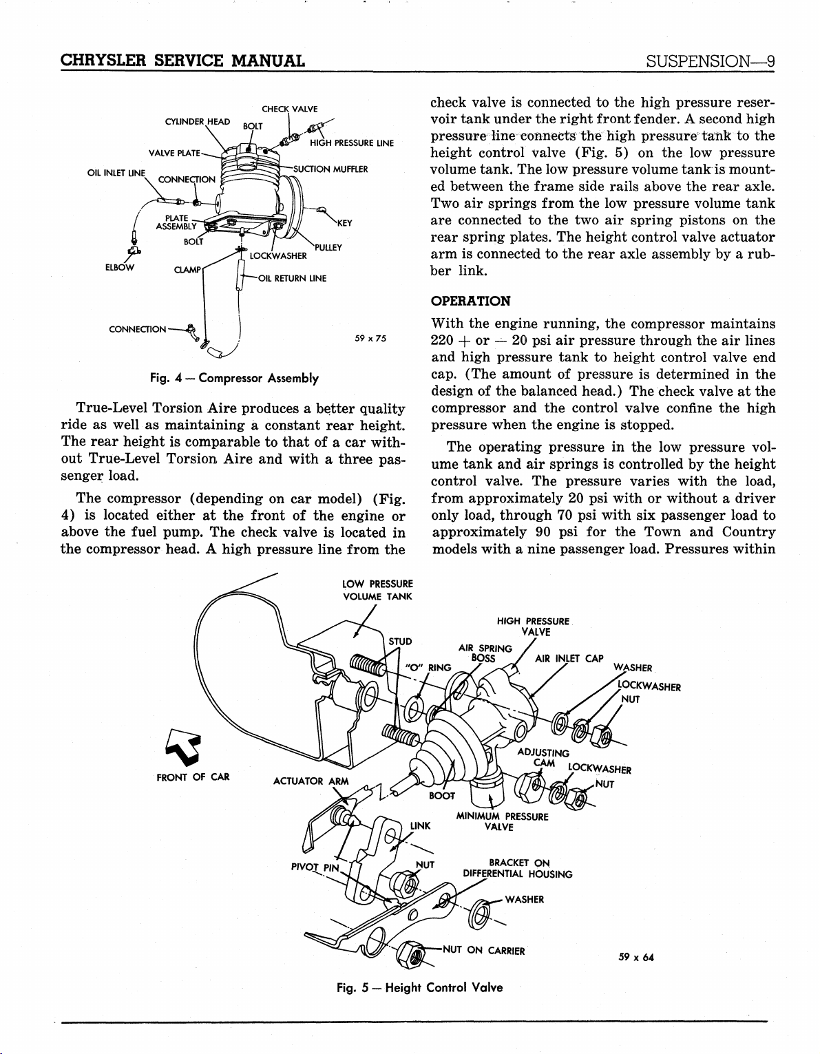
Fig.
4 — Compressor Assembly
True-Level Torsion Aire produces a better quality
ride as well as maintaining a constant rear height.
The rear height is comparable to that of a car without True-Level Torsion Aire and with a three passenger load.
The compressor (depending on car model) (Fig.
4) is located either at the front of the engine or
above the fuel pump. The check valve is located in
the compressor head. A high pressure line from the
check valve is connected to the high pressure reservoir tank under the right front fender. A second high
pressure line connects the high pressure" tank to the
height control valve (Fig. 5) on the low pressure
volume tank. The low pressure volume tank is mounted between the frame side rails above the rear axle.
Two air springs from the low pressure volume tank
are connected to the two air spring pistons on the
rear spring plates. The height control valve actuator
arm is connected to the rear axle assembly by a rubber link.
OPERATION
With the engine running, the compressor maintains
220 + or — 20 psi air pressure through the air lines
and high pressure tank to height control valve end
cap.
(The amount of pressure is determined in the
design of the balanced head.) The check valve at the
compressor and the control valve confine the high
pressure when the engine is stopped.
The operating pressure in the low pressure volume tank and air springs is controlled by the height
control valve. The pressure varies with the load,
from approximately 20 psi with or without a driver
only load, through 70 psi with six passenger load to
approximately 90 psi for the Town and Country
models with a nine passenger load. Pressures within
FRONT OF CAR
LOW PRESSURE
VOLUME TANK
HIGH PRESSURE
BRACKET ON
DIFFERENTIAL HOUSING
•NUT ON CARRIER
VALVE
ADJUSTING
CAM
LOCKWASHER
CAP
NUT
WASHER
LOCKWASHER
NUT
59x64
Fig.
5 —Height Control Valve
MyMopar.com
10—SUSPENSION
CHRYSLER SERVICE MANUAL
this range vary instantly as the car moves over
chuck holes and expansion strips in the road surface,
in order to maintain the constant rear height. Since
these pressures are variable, it is not necessary to
test them.
The height control valve contains a minimum pres-
sure valve to maintain 8-15 psi in the air springs
SERVICE PROCEDURES
MAINTENANCE
The high pressure air tank (located under the right
front fender) should be drained at least once a
month. Depress the non-removable core in the drain
valve. (Should it ever be necessary to remove the
valve, remove the high pressure line at the check
valve FIRST.)
TESTING FOR LEAKS (Liquid Soap Method)
With the engine running, apply a diluted liquid soap
solution at the following locations where leaks would
cause bubbles: air springs and seats, height con-
trol valve mounting, air line connections, high pressure air tank, drain valve connection and outlet.
Stop the engine and remove the air line and check
valve from the compressor. Connect the air line and
check valve. Apply air pressure through the tank
drain valve. Coat check valve with soap solution. If
no leak is evident, wipe off soap solution before reinstallation.
Refrigerator Method (Refrigerant 12)
Add 150 pounds of weight to the center area of the
luggage compartment and raise car on a hoist. Discharge the high pressure tank by depressing the
valve core in the valve. Remove the minimum pressure valve from the height control valve. Disconnect
the rubber linkage from the differential housing
bracket and move the actuator arm manually to discharge all air from the low pressure volume tank.
With all air removed from the system, connect the
rubber linkage and install the minimum pressure
valve.
Install adaptor Tool C-3693 between the high
pressure air line and the compressor check valve.
Connect manifold gauge set, Tool C-3627 (used with
air conditioning) on adaptor, Tool C-3693, using
the gauge set suction hose. Attach the refrigerant
tank to the gauge set. Open the suction side of the
gauge set and charge the system with 40 psi of refrigerant 12. Shut off the gauge set and start the car
during a no-load operation as in changing tires by
use of a bumper jack. This pressure prevents damage to the air spring as the jack is lowered and a load
condition restored to the system.
The height control valve also contains a high pressure relief valve (150 psi) to protect the system
under extreme heavy load conditions.
engine. Operate the car engine until normal operat-
ing pressure of 200 + or — 20 psi is obtained.
Using leak detector, Tool C-3659, (used with air
conditioning) check the entire True-Level Torsion
Aire System for leaks and make all necessary repairs.
CAUTION
Be sure no gasoline is leaking from the car system
when checking the True-Level Torsion Aire System
with Tool C-3659.
With the car engine running, purge the refrigerant from the system by disconnecting the rubber
linkage from the differential housing and manually
operating the height control valve actuator arm.
With the refrigerant purged from the system, connect the rubber linkage to its bracket. Shut off the
car engine and again discharge all air from the high
pressure tank. Remove adaptor Tool C-3693 from
the air line and check valve. Connect the air line to
the check valve. Lower the hoist and remove the
weight from the luggage compartment. Operate the
car engine approximately three minutes before removing the car from the hoist.
CHECKING
The vehicle must have recommended tire pressures,
full tank of fuel (or equivalent weight added to luggage compartment over the tank). (Gasoline weighs
approximately 6% pounds per gallon.) The front
suspension height should be correct and equal on
both sides before placing car on level floor with no
passenger load.
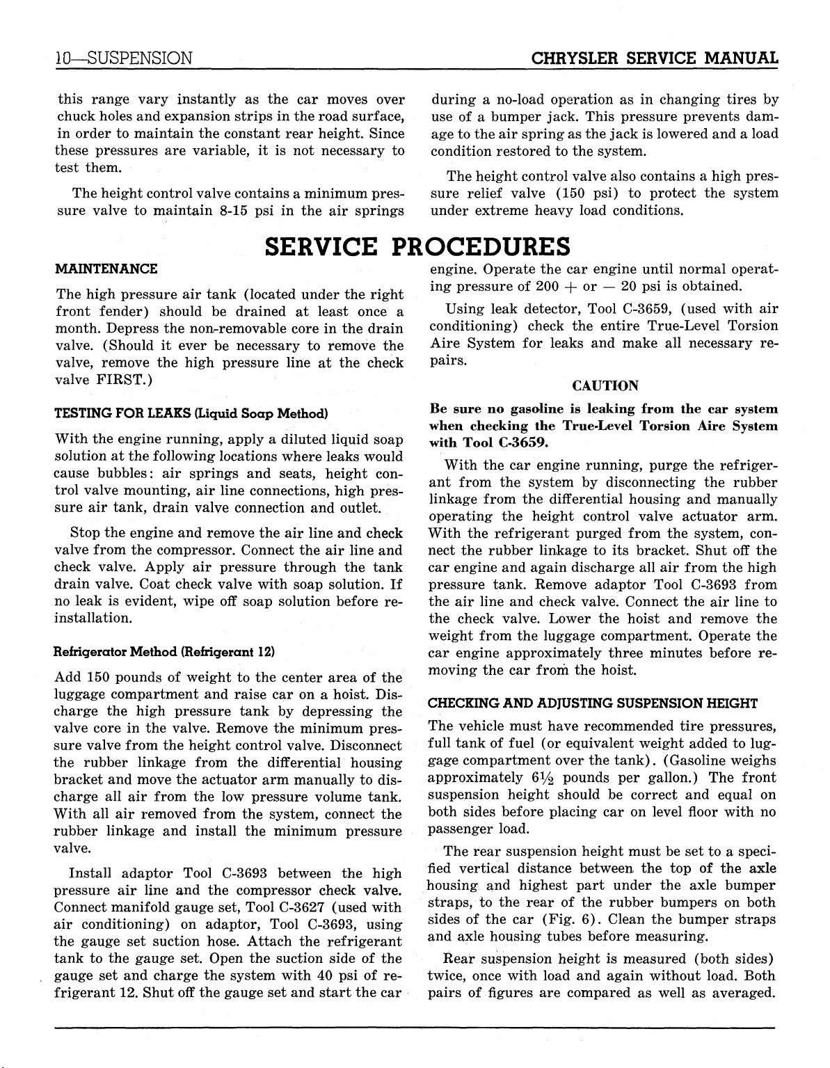
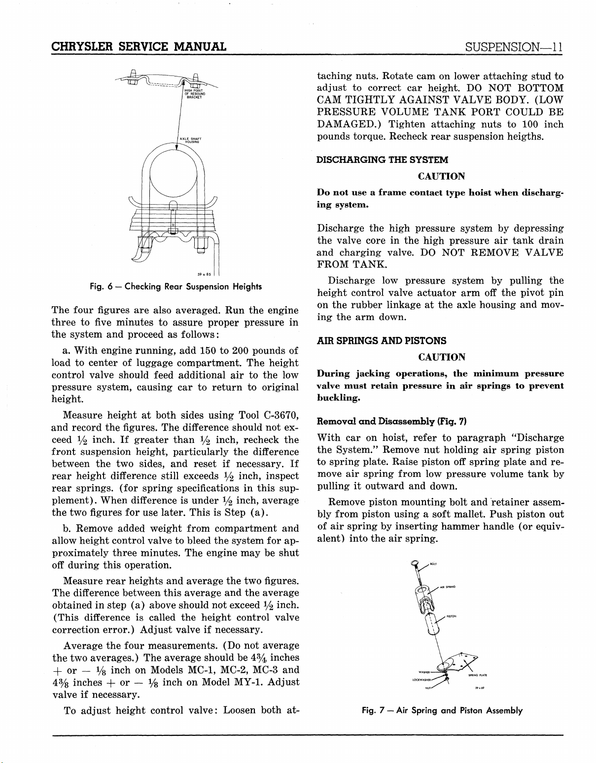
The rear suspension height must be set to a speci-
fied vertical distance between, the top of the axle
housing and highest part under the axle bumper
straps,
sides of the car (Fig. 6). Clean the bumper straps
and axle housing tubes before measuring.
Rear suspension height is measured (both sides)
twice, once with load and again without load. Both
pairs of figures are compared as well as averaged.
AND
ADJUSTING SUSPENSION HEIGHT
to the rear of the rubber bumpers on both
MyMopar.com
CHRYSLER SERVICE MANUAL
SUSPENSION—11
taching nuts. Rotate cam on lower attaching stud to
adjust to correct car height. DO NOT BOTTOM
CAM TIGHTLY AGAINST VALVE BODY. (LOW
PRESSURE VOLUME TANK PORT COULD BE
DAMAGED.) Tighten attaching nuts to 100 inch
pounds torque. Recheck rear suspension heigths.
Fig. 6 — Checking Rear Suspension Heights
The four figures are also averaged. Run the engine
three to fiwe minutes to assure proper pressure in
the system and proceed as follows:
a. With engine running, add 150 to 200 pounds of
load to center of luggage compartment. The height
control valve should feed additional air to the low
pressure system, causing car to return to original
height.
Measure height at both sides using Tool C-3670,
and record the figures. The difference should not ex-
ceed */2 inch. If greater than % inch, recheck the
front suspension height, particularly the difference
between the two sides, and reset if necessary. If
rear height difference still exceeds */2 inch, inspect
rear springs, (for spring specifications in this supplement). When difference is under
y%
inch, average
the two figures for use later. This is Step (a).
b.
Remove added weight from compartment and
allow height control valve to bleed the system for approximately three minutes. The engine may be shut
off during this operation.
Measure rear heights and average the two figures.
The difference between this average and the average
obtained in step (a) above should not exceed % inch.
(This difference is called the height control valve
correction error.) Adjust valve if necessary.
Average the four measurements. (Do not average
the two averages.) The average should be 4% inches
+ or — y8 inch on Models MC-1, MC-2, MC-3 and
4%
inches -(-or — Vs inch on Model MY-1. Adjust
valve if necessary.
To adjust height control valve: Loosen both at-
DISCHARGING
THE
SYSTEM
CAUTION
Do not use a frame contact type hoist when discharging system.
Discharge the high pressure system by depressing
the valve core in the high pressure air tank drain
and charging valve. DO NOT REMOVE VALVE
FROM TANK.
Discharge low pressure system by pulling the
height control valve actuator arm off the pivot pin
on the rubber linkage at the axle housing and moving the arm down.
AIR SPRINGS
AND
PISTONS
CAUTION
During jacking operations, the minimum pressure
valve must retain pressure in air springs to prevent
buckling.
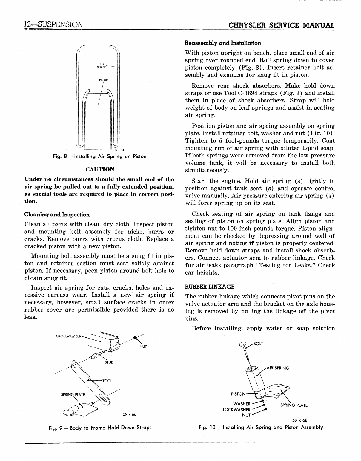
Removal and Disassembly
(Fig.
7)
With car on hoist, refer to paragraph "Discharge
the System." Remove nut holding air spring piston
to spring plate. Raise piston off spring plate and re-
move air spring from low pressure volume tank by
pulling it outward and down.
Remove piston mounting bolt and retainer assembly from piston using a soft mallet. Push piston out
of air spring by inserting hammer handle (or equivalent) into the air spring.
Fig, 7 —
Air
Spring
and
Piston Assembly
MyMopar.com
12—SUSPENSION
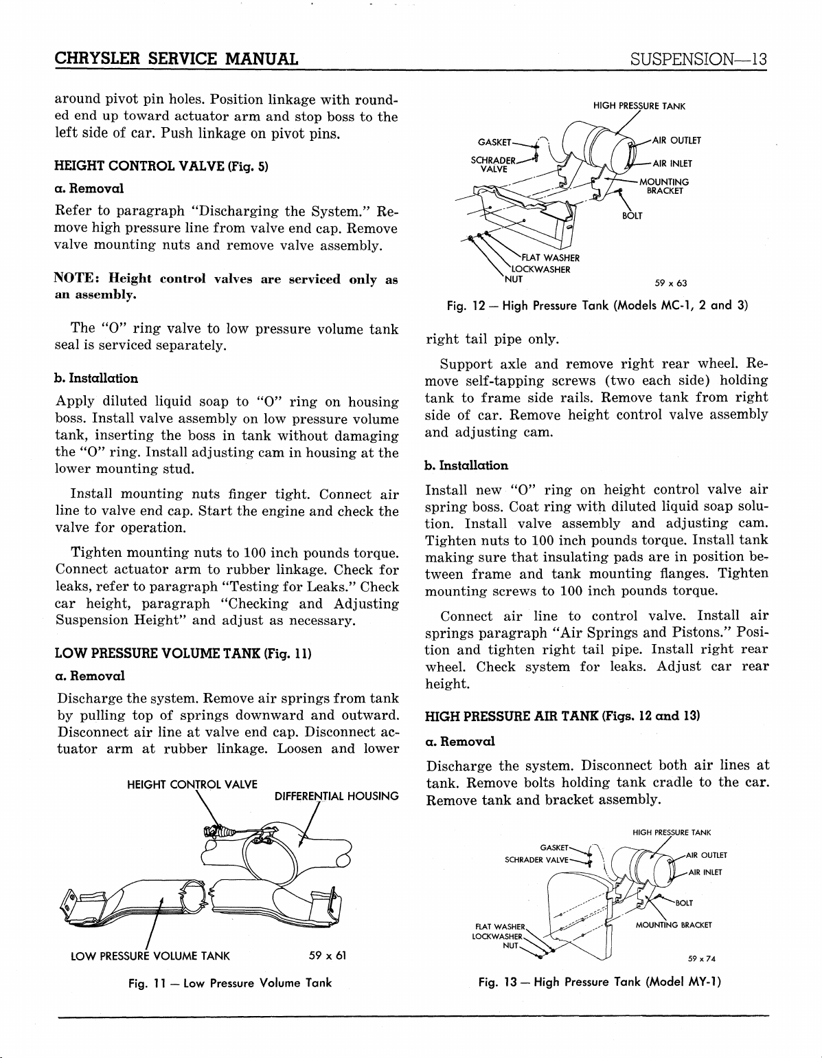
Fig.
8 — Installing Air Spring on Piston
CAUTION
Under no circumstances should the small end of the
air spring be pulled out to a fully extended position,
as special tools are required to place in correct position.
CHRYSLER SERVICE MANUAL
Reassembly and Installation
With piston upright on bench, place small end of air
spring over rounded end. Roll spring down to cover
piston completely (Fig. 8). Insert retainer bolt assembly and examine for snug fit in piston.
Remove rear shock absorbers. Make hold down
straps or use Tool C-3694 straps (Fig. 9) and install
them in place of shock absorbers. Strap will hold
weight of body on leaf springs and assist in seating
air spring.
Position piston and air spring assembly on spring
plate. Install retainer bolt, washer and nut (Fig. 10).
Tighten to 5 foot-pounds torque temporarily. Coat
mounting rim of air spring with diluted liquid soap.
If both springs were removed from the low pressure
volume tank, it will be necessary to install both
simultaneously.
Start the engine. Hold air spring (s) tightly in
position against tank seat (s) and operate control
valve manually. Air pressure entering air spring (s)
will force spring up on its seat.
Cleaning and Inspection
Clean all parts with clean, dry cloth. Inspect piston
and mounting bolt assembly for nicks, burrs or
cracks. Remove burrs with crocus cloth. Replace a
cracked piston with a new piston.
Mounting bolt assembly must be a snug fit in pis-
ton and retainer section must seat solidly against
piston. If necessary, peen piston around bolt hole to
obtain snug fit.
Inspect air spring for cuts, cracks, holes and ex-
cessive carcass wear. Install a new air spring if
necessary, however, small surface cracks in outer
rubber cover are permissible provided there is no
leak.
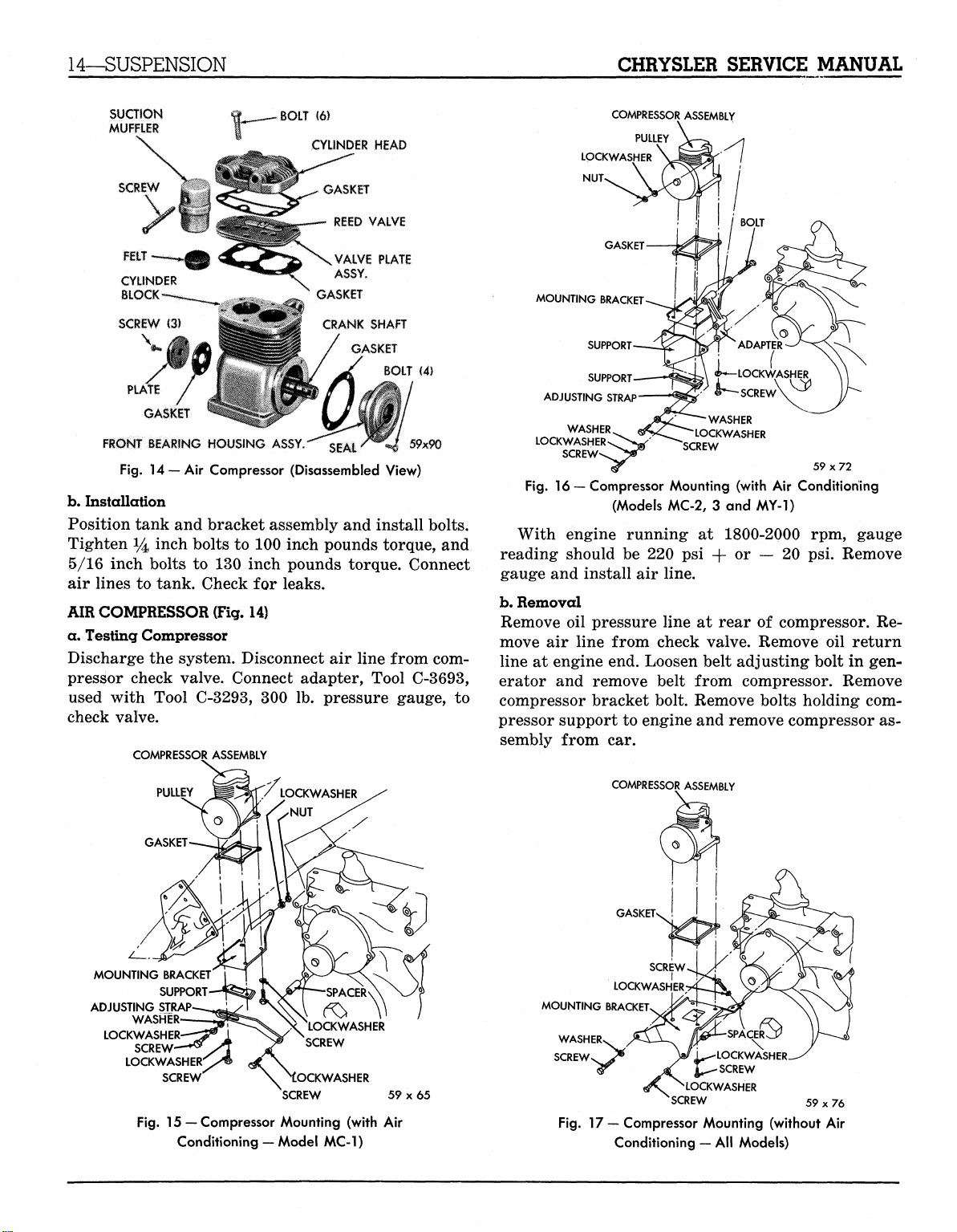
CROSSMEMBER
NUT
Check seating of air spring on tank flange and
seating of piston on spring plate. Align piston and
tighten nut to 100 inch-pounds torque. Piston alignment can be checked by depressing around wall of
air spring and noting if piston is properly centered.
Remove hold down straps and install shock absorbers.
Connect actuator arm to rubber linkage. Check
for air leaks paragraph "Testing for Leaks." Check
car heights.
RUBBER LINKAGE
The rubber linkage which connects pivot pins on the
valve actuator arm and the bracket on the axle hous-
ing is removed by pulling the linkage off the pivot
pins.
Before installing, apply water or soap solution
BOLT
AIRSPRING
59 x 66
Fig.
9 — Body to Frame Hold Down Straps
PISTON
WASHER
LOCKWASHER
Fig.
10 — Installing Air Spring and Piston Assembly
NUT
MyMopar.com
CHRYSLER SERVICE MANUAL
SUSPENSION—13
around pivot
ed
end up
left side
HEIGHT CONTROL VALVE (Fig.
a. Removal
Refer
to
move high pressure line from valve
valve mounting nuts
NOTE:
pin
holes. Position linkage with round-
toward actuator
of car.
Push linkage
arm and
on
paragraph "Discharging
and
remove valve assembly.
Height control valves
stop boss
pivot pins.
5)
the
System."
end
are
serviced only
cap. Remove
an assembly.
The
"0"
ring valve
seal
is
serviced separately.
b.
Installation
Apply diluted liquid soap
boss.
Install valve assembly
tank, inserting
the
the "O" ring. Install adjusting
to low
boss
pressure volume tank
to "0"
on low
in
tank without damaging
ring
on
pressure volume
cam in
housing
lower mounting stud.
Install mounting nuts finger tight. Connect
line
to
valve
end
cap. Start
valve
for
operation.
Tighten mounting nuts
Connect actuator
leaks,
refer
arm to
to
paragraph "Testing
car height, paragraph "Checking
Suspension Height"
LOW PRESSURE VOLUME TANK (Fig.
a. Removal
Discharge
by pulling
Disconnect
tuator
the
top of
air
arm at
HEIGHT CONTROL VALVE
and
system. Remove
springs downward
line
at
rubber linkage. Loosen
the
engine
to 100
and
inch pounds torque.
rubber linkage. Check
for
Leaks." Check
and
adjust
as
necessary.
11)
air
springs from tank
and
valve
end cap.
Disconnect
DIFFERENTIAL HOUSING
Adjusting
and
to the
Re-
as
housing
at the
air
check
the
for
outward.
ac-
lower
HIGH PRESSURE TANK
AIR OUTLET
59x63
2 and 3)
Fig.
GASKET
SCHRADER
VALVE
'FLAT WASHER
\ NLOCKWASHER
NUT
12 -
High Pressure Tank (Models MC-1,
right tail pipe only.
Support axle
move self-tapping screws
tank
to
frame side rails. Remove tank from right
side
of car.
and adjusting
b.
Installation
Install
new "0"
and
remove right rear wheel.
(two
each side) holding
Re-
Remove height control valve assembly
cam.
ring
on
height control valve
air
spring boss. Coat ring with diluted liquid soap solu-
tion. Install valve assembly
Tighten nuts
to 100
inch pounds torque. Install tank
making sure that insulating pads
tween frame
mounting screws
Connect
springs paragraph
tion
and
wheel. Check system
and
tank mounting flanges. Tighten
to 100
air
line
to
"Air
tighten right tail pipe. Install right rear
for
and
adjusting
are in
cam.
position
inch pounds torque.
control valve. Install
Springs
and
Pistons." Posi-
leaks. Adjust
car
be-
air
rear
height.
HIGH PRESSURE AIR TANK (Figs. 12
a. Removal
Discharge
the
system. Disconnect both
tank. Remove bolts holding tank cradle
Remove tank
and
bracket assembly.
and 13)
air
to the car.
lines
at
LOW PRESSURE VOLUME TANK
Fig.
11 — Low
Pressure Volume Tank
59 x 61
GASKET
SCHRADER VALVE
FLAT WASHER
LOCKWASHER
NUT
Fig.
13 - High Pressure Tank (Model
HIGH PRESSURE TANK
AIR OUTLET
AIR INLET
BOLT
MOUNTING BRACKET
59x74
MY-1)
MyMopar.com
14—SUSPENSION
CHRYSLER SERVICE MANUAL
SUCTION
MUFFLER
FELT
CYLINDER
BLOCK
SCREW
C3)
\
FRONT SEARING HOUSING
Fig.
14
—Air Compressor (Disassembled View)
b.
Installation
Position tank and bracket assembly and install bolts.
Tighten 14 i
5/16 inch bolts
ncn
bolts to 100 inch pounds torque, and
to
130 inch pounds torque. Connect
air lines to tank. Check
AIR COMPRESSOR (Fig.
for
14)
BOLT
ASSY.
leaks.
(6)
CYLINDER HEAD
^^
GASKET
REED VALVE
VALVE PLATE
ASSY.
GASKET
CRANK SHAFT
GASKET
SEAL'**
BOLT
59x90
(4)
a. Testing Compressor
Discharge the system. Disconnect
air
line from com-
pressor check valve. Connect adapter, Tool C-3693,
used with Tool C-3293,
300 lb.
pressure gauge,
to
check valve.
COMPRESSOR ASSEMBLY
COMPRESSOR ASSEMBLY
PULLEY
LOCKWASHER
NUT>
BOLT
MOUNTING BRACKET
SUPPORT
SUPPORT
ADJUSTING STRAP
WASHER
LOCKWASHER
Fig.
16 — Compressor Mounting (with Air Conditioning
(Models MC-2, 3 and MY-1)
With engine running
reading should
gauge and install
b.
Removal
Remove
move
line
erator
oil
air
at
engine end. Loosen belt adjusting bolt in gen-
and
be 220 psi
air
line.
pressure line
line from check valve. Remove
remove belt from compressor. Remove
i^LOCKWASHER
«^- SCREW
WASHER
LOCKWASHER
SCREW
at
1800-2000
or
+
at
rear
o
ADAPTER
—
20 psi.
of
compressor.
59x72
rpm,
Remove
oil
gauge
Re-
return
compressor bracket bolt. Remove bolts holding com-
pressor support to engine and remove compressor as-
sembly from
car.
PU
MOUNTING BRACKET
ADJUSTING STRAP
LOCKWASHER
SUPPORT
WASHER
SCREW
LOCKWASHERO^
SCREW
Fig.
15— Compressor Mounting (with Air
Conditioning — Model MC-1)
I I
LOCKWASHER
SCREW
OCKWASHER
SCREW
59x65
COMPRESSOR ASSEMBLY
GASKET
MOUNTING BRACKET
WASHER
SCREWS ^ Vi^
Fig.
17 —
Compressor Mounting (without
Conditioning
LOCKWASHER
JSCREW
*
LOCKWASHER
'SCREW
59x76
— All
Models)
-
Air
MyMopar.com
CHRYSLER SERVICE MANUAL
SUSPENSION—15
c. Installation
(Figs.
15,16 and 17)
With compressor attached to support, attach support
to engine, tightening- bolts to 30 foot pounds torque.
Install compressor bracket. Tighten bolt to 30 foot
pounds torque.
Install belt (see "Accessory Belt Drives" in this
supplement for adjustment). Connect oil pressure
line,
air line and oil return line. Start engine and
check lines for leaks. Test air pressure.
COMPRESSOR RECONDITIONING
The following components parts are available for
service:
(1) Cylinder head and gasket
(2) Valve plate assembly and gasket
(3) Pulley and key
(4) Bottom plate, mounting plate and gasket
(5) Front bearing, housing and oil seal assembly
(6) Check valve assembly
(7) Suction muffler felt
CYLINDER HEAD AND/OR VALVE PLATE ASSEMBLY
Discharge the system. Remove air line from check
valve. Remove cylinder head bolts. Remove cylinder
head and valve plate assembly. If the plate does not
separate from the head, tap the plate lightly with a
soft mallet. Do not pry apart.
Clean piston heads, top of the cylinder block and
head bolt holes, cylinder head and valve plate, using
mineral spirits. Do not use scraper. Inspect pistons
and cylinder walls. If damaged, replace the compressor. If valve plate or cylinder head is damaged,
replace. Remove check valve only if replacement is
necessary.
Use new gaskets when installing valve plate and
cylinder head. Tighten bolts to 155 inch pounds
COMPRESSOR
59x91
TOOL
PULLEY
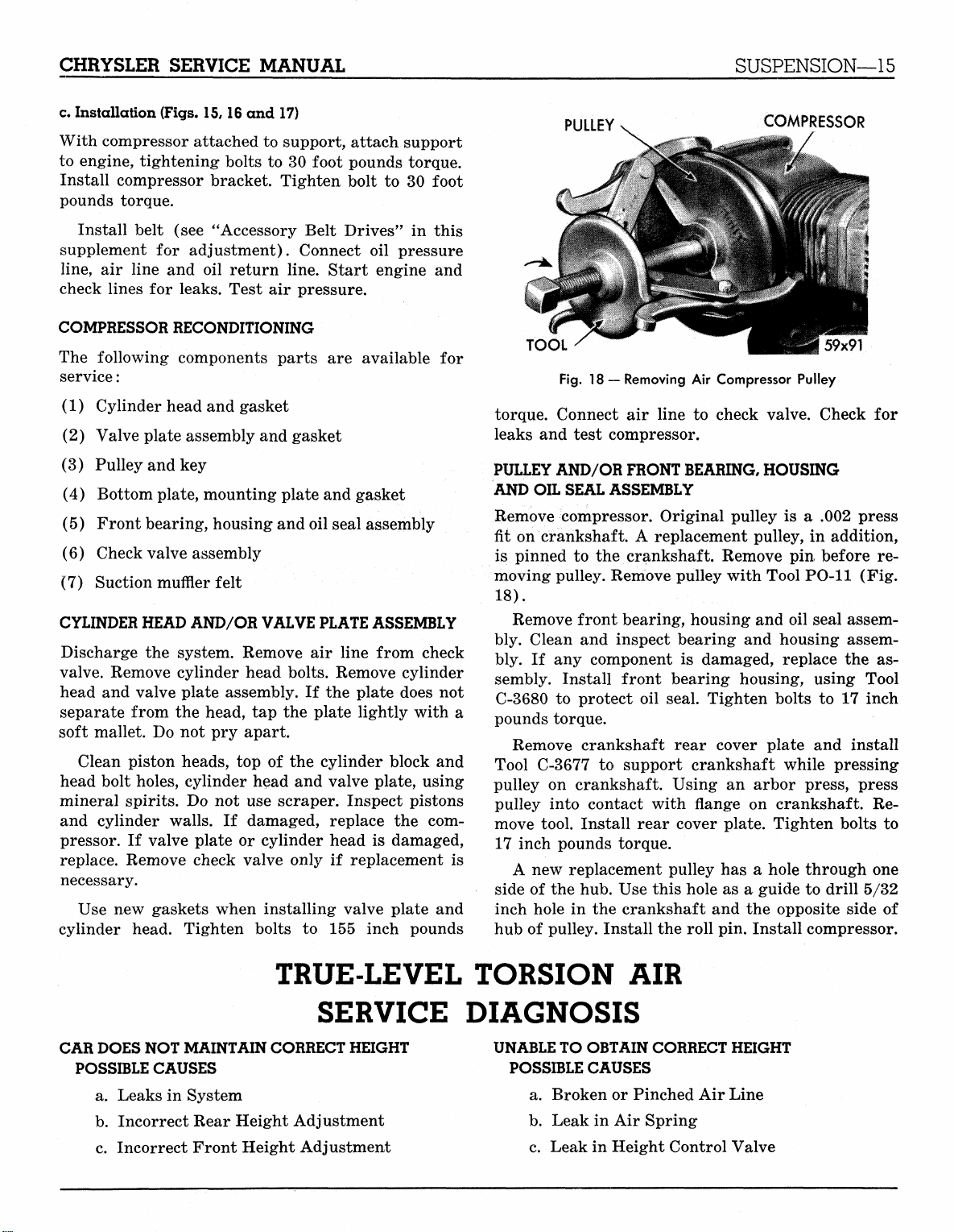
Fig.
18 — Removing Air Compressor Pulley
torque. Connect air line to check valve. Check for
leaks and test compressor.
PULLEY AND/OR FRONT BEARING, HOUSING
AND OIL SEAL ASSEMBLY
Remove compressor. Original pulley is a .002 press
fit on crankshaft. A replacement pulley, in addition,
is pinned to the crankshaft. Remove pin before re-
moving pulley. Remove pulley with Tool PO-11 (Fig.
18).
Remove front bearing, housing and oil seal assem-
bly. Clean and inspect bearing and housing assembly. If any component is damaged, replace the assembly. Install front bearing housing, using Tool
C-3680 to protect oil seal. Tighten bolts to 17 inch
pounds torque.
Remove crankshaft rear cover plate and install
Tool C-3677 to support crankshaft while pressing
pulley on crankshaft. Using an arbor press, press
pulley into contact with flange on crankshaft. Remove tool. Install rear cover plate. Tighten bolts to
17 inch pounds torque.
A new replacement pulley has a hole through one
side of the hub. Use this hole as a guide to drill 5/32
inch hole in the crankshaft and the opposite side of
hub of pulley. Install the roll pin. Install compressor.
TRUE-LEVEL TORSION AIR
CAR
DOES
NOT
MAINTAIN CORRECT
POSSIBLE
a. Leaks in System
b.
c. Incorrect Front Height Adjustment
CAUSES
Incorrect Rear Height Adjustment
SERVICE DIAGNOSIS
HEIGHT
UNABLE TO OBTAIN
POSSIBLE
a. Broken or Pinched Air Line
b.
c. Leak in Height Control Valve
CAUSES
Leak in Air Spring
CORRECT
HEIGHT
MyMopar.com
16—AXLE—REAR
CHRYSLER SERVICE MANUAL
d. Fast Leak in Low Pressure Volume Tank
e. Height Control Valve Out of Adjustment
f. Rubber Linkage Loose or Broken at Differen-
tial
g. Broken Height Control Actuator Arm
LOW AIR PRESSURE
POSSIBLE CAUSES
a. Leak in Air Line
b.
Compressor Belt Broken or Out of Adjust-
ment
c. Slipping Drive Belt
d. Plugged Check Valve
REAR AXLE
DATA AND SPECIFICATIONS
e. Leaking Cylinder Head Gasket
f. Leaking Valve Plate Gasket
g. Cracked Cylinder Head
h. Worn Reed Valves
i. Excessive Cylinder Wall Wear
j.
EXCESSIVE AIR PRESSURE
POSSIBLE CAUSES
a. Carbon Build Up on Cylinder Head
b.
c. Excessive Oil on Top of Piston
Section II
Excessive Piston Ring Wear
Carbon Build Up on Pistons
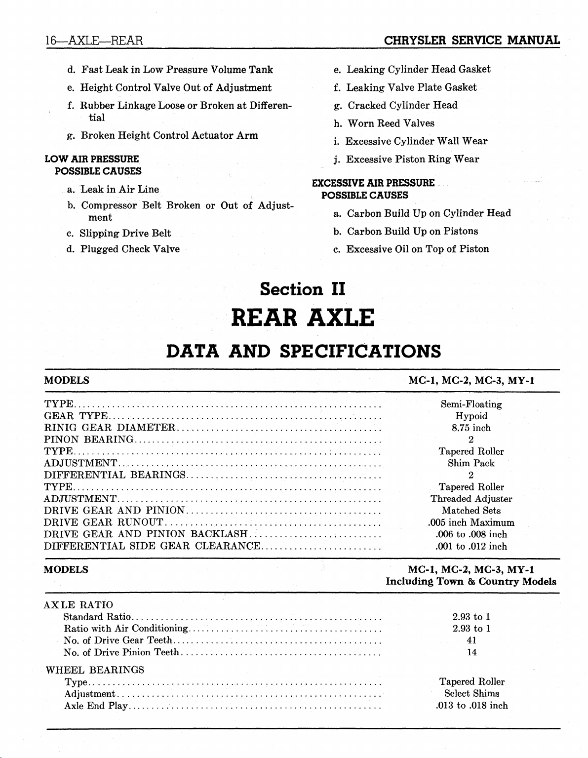
MODELS MC-1, MC-2, MC-3, MY-1
TYPE Semi-Floating
GEAR TYPE -.. Hypoid
RINIG GEAR DIAMETER... 8.75 inch
PINON BEARING 2
TYPE .....: Tapered Roller
ADJUSTMENT Shim Pack
DIFFERENTIAL BEARINGS 2
TYPE Tapered Roller
ADJUSTMENT Threaded Adjuster
DRIVE GEAR AND PINION. Matched Sets
DRIVE GEAR RUNOUT .005 inch Maximum
DRIVE GEAR AND PINION BACKLASH. .006 to .008 inch
DIFFERENTIAL SIDE GEAR CLEARANCE .001 to .012 inch
MODELS MC-1, MC-2, MC-3, MY-1
Including Town
AXLE RATIO
Standard Ratio .. 2.93 to 1
Ratio with Air Conditioning 2.93 to 1
No.
of Drive Gear Teeth 41
No.
of Drive Pinion Teeth 14
8B
Country Models
WHEEL BEARINGS
Type. Tapered Roller
Adjustment Select Shims
Axle End Play .013 to .018 inch
MyMopar.com
CHRYSLER SERVICE MANUAL
BRAKES—17
REAR AXLE
There is no basic design change in the rear axle and
sure grip differential except the larger diameter
pinion shaft is now used on all models for 1959. The
Service Procedures will remain the same on the Rear
Section
Axle and Sure Grip Differential as specified in the
1958 Chrysler and Imperial Service Manual, D-
16350.
III
BRAKES
DATA
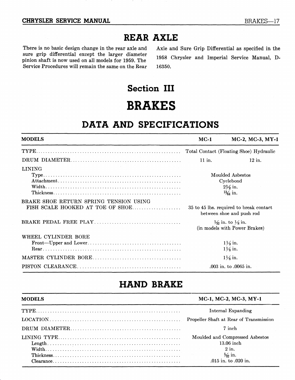
MODELS
TYPE Total Contact (Floating Shoe) Hydraulic
DRUM DIAMETER
LINING
MC-1
... ,
Type Moulded Asbestos
Attachment Cyclebond
Width 2Y2 in.
Thickness
l
AND
SPECIFICATIONS
MC-2, MC-3,
11
in.
12
%i
MY-1
in.
in-
BRAKE SHOE RETURN SPRING TENSION USING
FISH SCALE HOOKED
BRAKE PEDAL FREE PLAY
WHEEL CYLINDER BORE
Front—Upper
Rear
1K mMASTER CYLINDER BORE V/% in.
PISTON CLEARANCE .003
and
AT TOE OF
% in. to J^ in.
Lower 1%
SHOE 35
to
45 lbs. required
between shoe
(in models with Power Brakes)
in. to
to
break contact
and
push
in.
.0065
in.
HAND BRAKE
MODELS MC-1, MC-2, MC-3,
TYPE Internal Expanding
LOCATION Propeller Shaft
DRUM DIAMETER.
LINING TYPE
Length 13.06 inch
Width
2 in.
Thickness
Clearance .015
%
7
,
Moulded
at
Rear
inch
and
Compressed Asbestos
m
in. to
MY-1
of
Transmission
-
.020
in.
MyMopar.com
rod
18—BRAKES
CHRYSLER SERVICE MANUAL
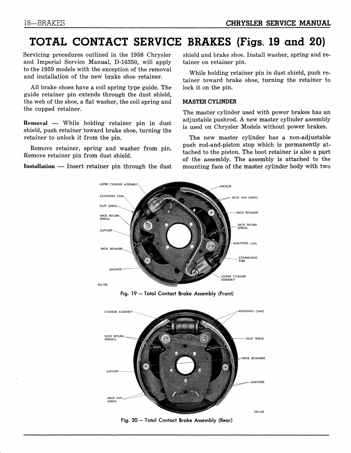
TOTAL CONTACT SERVICE BRAKES
Servicing procedures outlined in the 1958 Chrysler
and Imperial Service Manual, D-16350, will apply
to the 1959 models with the exception of the removal
and installation of the new brake shoe retainer.
All brake shoes have a coil spring type guide. The
guide retainer pin extends through the dust shield,
the web of the shoe, a flat washer, the coil spring and
the cupped retainer.
Removal — While holding retainer pin in dust
shield, push retainer toward brake shoe, turning the
retainer to unlock it from the pin.
Remove retainer, spring and washer from pin.
Remove retainer pin from dust shield.
Installation — Insert retainer pin through the dust
UPPER CYLINDER
ADJUSTING
CAM
DUST SHIELD-v.
SHOE RETURN
SPRING
SUPPORT-^
shield and brake shoe. Install washer, spring and retainer on retainer pin.
While holding retainer pin in dust shield, push retainer toward brake shoe, turning the retainer to
lock it on the pin.
MASTER CYLINDER
The master cylinder used with power brakes has an
adjustable pushrod. A new master cylinder assembly
is used on Chrysler Models without power brakes.
The new master cylinder has a non-adjustable
push rod-and-piston stop which is permanently attached to the piston. The boot retainer is also a part
of the assembly. The assembly is attached to the
mounting face of the master cylinder body with two
(Figs.
.- SHOE
AND
UNING
— SHOE RETAINER
SHOE RETURN
:
SPRING
19 and 20)
SHOE RETAINE
CYLINDER ASSEMBLY
SHOE
RE'
SPRINGS
SUPPORT
SHOE AND
LINING
Fig.
19
—Total Contact Brake Assembly (Front)
^**z~~-
-ADJUSTING
CONNECTING
TUBE
LOWfi? CYLINDER
ADJUSTING CAMS
CAM
DUST SHIELD
SHOE RETAINERS
ANCHORS
Fig.
20 — Total Contact Brake Assembly (Rear)
MyMopar.com
CHRYSLER SERVICE MANUAL
BRAKES—19
screws. No attempt should be made to disassemble
this push rod and piston.
The combined action of the piston return spring
and the pressure in the master cylinder is sufficient
to hold the brake pedal in the "off" position, without
a pedal return spring and pedal stop. The brake
pedal should never be pulled back beyond the limit
controlled by the piston stop. A minimum pull of 50
pounds could pull the piston off the push rod.
PISTON TYPE POWER BRAKE UNIT
The 1959 Chrysler and Imperial Models will have
both the "Bellows Type" Power Brake as well as the
"Piston, Type." The servicing procedure for the "Bellows Type" is the same as that in the 1958 Chrysler
and Imperial Service Manual. The servicing procedure for the "Piston Type" is outlined below:
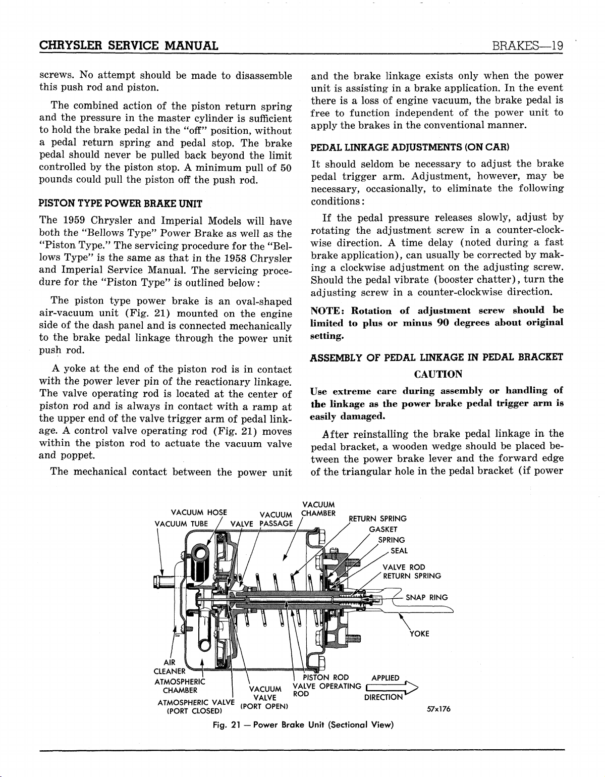
The piston type power brake is an oval-shaped
air-vacuum unit (Fig. 21) mounted on the engine
side of the dash panel and is connected mechanically
to the brake pedal linkage through the power unit
push rod.
A yoke at the end of the piston rod is in contact
with the power lever pin of the reactionary linkage.
The valve operating rod is located at the center of
piston rod and is always in contact with a ramp at
the upper end of the valve trigger arm of pedal linkage.
A control valve operating rod (Fig. 21) moves
within the piston rod to actuate the vacuum valve
and poppet.
The mechanical contact between the power unit
and the brake linkage exists only when the power
unit is assisting in a brake application. In the event
there is a loss of engine vacuum, the brake pedal is
free to function independent of the power unit to
apply the brakes in the conventional manner.
PEDAL LINKAGE ADJUSTMENTS (ON CAR)
It should seldom be necessary to adjust the brake
pedal trigger arm. Adjustment, however, may be
necessary, occasionally, to eliminate the following
conditions:
If the pedal pressure releases slowly, adjust by
rotating the adjustment screw in a counter-clockwise direction. A time delay (noted during a fast
brake application), can usually be corrected by mak-
ing a clockwise adjustment on the adjusting screw.
Should the pedal vibrate (booster chatter), turn the
adjusting screw in a counter-clockwise direction.
NOTE: Rotation of adjustment screw should be
limited to plus or minus 90 degrees about original
setting.
ASSEMBLY OF PEDAL LINKAGE IN PEDAL BRACKET
CAUTION
Use extreme care during assembly or handling of
the linkage as the power brake pedal trigger arm is
easily damaged.
After reinstalling the brake pedal linkage in the
pedal bracket, a wooden wedge should be placed between the power brake lever and the forward edge
of the triangular hole in the pedal bracket (if power
VACUUM HOSE VACUUM CHAMBER
VACUUM TUBE / VALVE PASSAGE
AIR
CLEANER
ATMOSPHERIC
CHAMBER
ATMOSPHERIC VALVE
(PORT CLOSED)
Fig.
VACUUM
VALVE
(PORT OPEN)
21
—Power Brake Unit (Sectional View)
/
VALVE OPERATING
ROD
VACUUM
RETURN SPRING
GASKET
SPRING
SEAL
VALVE
RETURN SPRING
£
DIRECTION
ROD
57x176
MyMopar.com
20—BRAKES
CHRYSLER SERVICE MANUAL
ARBOR f-<
(TOOL) ^
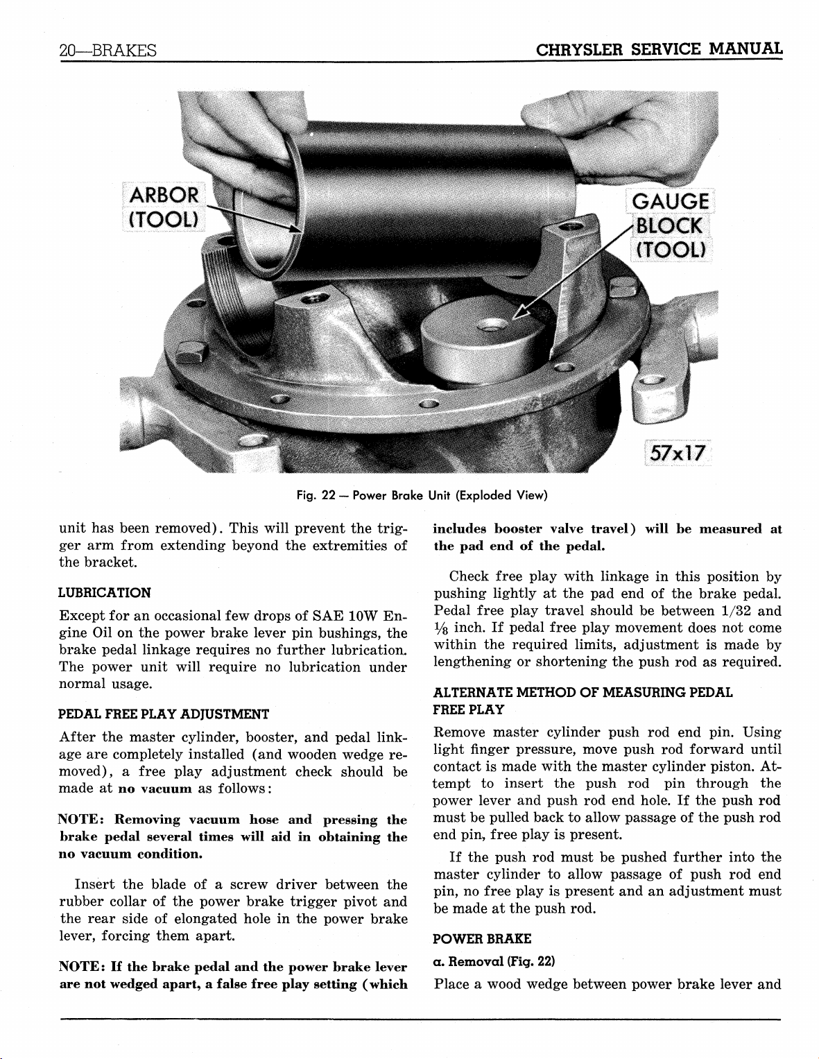
Fig.
22 - Power Brake Unit (Exploded View)
unit has been removed). This will prevent the trigger arm from extending beyond the extremities of
the bracket.
LUBRICATION
Except for an occasional few drops of SAE 10W Engine Oil on the power brake lever pin bushings, the
brake pedal linkage requires no further lubrication.
The power unit will require no lubrication under
normal usage.
PEDAL FREE PLAY ADJUSTMENT
After the master cylinder, booster, and pedal linkage are completely installed (and wooden wedge removed), a free play adjustment check should be
made at no vacuum as follows:
NOTE: Removing vacuum hose and pressing the
brake pedal several times will aid in obtaining the
no vacuum condition.
Insert the blade of a screw driver between the
rubber collar of the power brake trigger pivot and
the rear side of elongated hole in the power brake
lever, forcing them apart.
NOTE: If the brake pedal and the power brake lever
are not wedged apart, a false free play setting (which
GAUGE
BLOCK
(TOOL)
57x17
includes booster valve travel) will be measured at
the pad end of the pedal.
Check free play with linkage in this position by
pushing lightly at the pad end of the brake pedal.
Pedal free play travel should be between 1/32 and
Vs inch. If pedal free play movement does not come
within the required limits, adjustment is made by
lengthening or shortening the push rod as required.
ALTERNATE METHOD OF MEASURING PEDAL
FREE PLAY
Remove master cylinder push rod end pin. Using
light finger pressure, move push rod forward until
contact is made with the master cylinder piston. Attempt to insert the push rod pin through the
power lever and push rod end hole. If the push rod
must be pulled back to allow passage of the push rod
end pin, free play is present.
If the push rod must be pushed further into the
master cylinder to allow passage of push rod end
pin, no free play is present and an adjustment must
be made at the push rod.
POWER BRAKE
a. Removal (Fig. 22)
Place a wood wedge between power brake lever and
MyMopar.com
CHRYSLER SERVICE MANUAL
BRAKES—21
forward edge
prevent trigger
ities
of
NOTE:
hole
If
in
of
triangular hole
arm
bracket.
pedal linkage
dash panel
from extending beyond extrem-
the
trigger
Disconnect vacuum hose
attaching bolts
at
dash panel
power unit assembly.
NOTE: Use care
cross
pin.
b.
Disassembly
Scribe across flange
guide
to
correct assembly (Fig.
NOTE:
Do not
to
prevent loss
of
clamp yoke
tion.
Remove
ing
the
the
cylinder shell
vacuum hose from
CAUTION
The vacuum tube must
(Fig.
4).
diaphragm
Make certain
is in the
the
annular groove
plate assembly.
Install valve
rod
poppet
NOTE: Before installing
the following test.
Depress
to blow through
through
the
valve
the
the
hose indicates
rod and at the
vacuum hose. Failure
properly seated.
VACUUM CYLINDER
AIR CLEANER
COVER
AIR CLEANER
HAIR
NUT (4)
in
pedal bracket,
is
allowed
to
extend through
arm may be
at
power unit. Remove
and
carefully remove
cylinder
of the
and end
pedal linkage
23).
in
vise during any opera-
and
gasket, disconnect-
the air
be in the
bead
cleaner cover.
lowest quadrant
at
outer diameter
of the
and
applying diaphragm.
the
vacuum cylinder, make
same time,
the
poppet assembly
END PLATE
MATING MARKS
damaged.
plate
as a
tube
and
try
to
blow
GASKET
to
of
is
END PLATE SPRING ROD
RETAINER PLATE
POPPET DIAPHRAGM
APPLYING
DIAPHRAGM
VALVE
ROD
APPLYING
SCREW
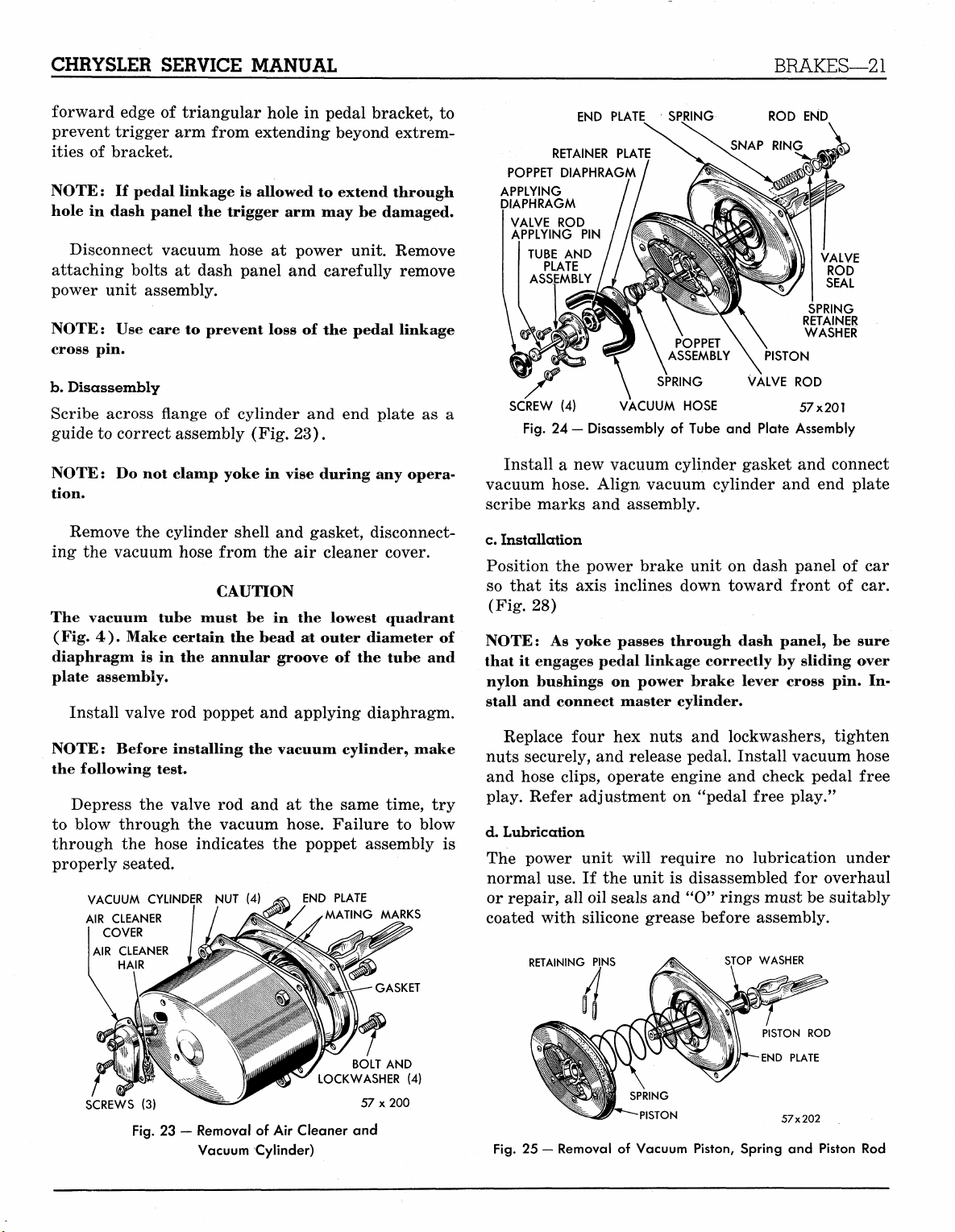
Fig.
Install
PIN
TUBE
AND
PLATE
ASSEMBLY
(4)
24
— Disassembly
a new
SPRING VALVE
VACUUM HOSE 57x201
of
Tube
and
vacuum cylinder gasket
vacuum hose. Align vacuum cylinder
scribe marks
and
assembly.
END
SPRING
RETAINER
WASHER
PISTON
ROD
Plate Assembly
and
and end
c. Installation
Position
so that
(Fig.
NOTE:
that
nylon bushings
stall
nuts securely,
and hose clips, operate engine
play. Refer adjustment
the
power brake unit
its
axis inclines down toward front
28)
As
yoke passes through dash panel,
it
engages pedal linkage correctly
on
power brake lever cross
and
connect master cylinder.
Replace four
hex
nuts
and
and
release pedal. Install vacuum hose
on
"pedal free play."
on
dash panel
by
sliding over
lockwashers, tighten
and
check pedal free
d. Lubrication
The power unit will require
normal use.
or repair,
If the
all
unit
oil seals
is
and
no
lubrication under
disassembled
for
"0" rings must be suitably
coated with silicone grease before assembly.
RETAINING PINS
STOP WASHER
VALVE
ROD
SEAL
connect
plate
of car
of car.
be
sure
pin. In-
overhaul
SCREWS
LOCKWASHER
(3)
Fig.
23 — Removal of Air Cleaner and
Vacuum Cylinder)
BOLT
57 x 200
AND
(4)
PISTON
ROD
END PLATE
57x202
Fig.
25 — Removal of Vacuum Piston, Spring and Piston Rod
MyMopar.com
22—BRAKES
CHRYSLER SERVICE MANUAL
LEATHER PACKING
EXPANDER SPRING
RETAINER PLATE
COTTON WICK
EXPANDER SPRING
SCREW
(6) W 57x203
Fig.
26
— Disassembly
of
Vacuum Piston
PISTON
PISTON PLATE
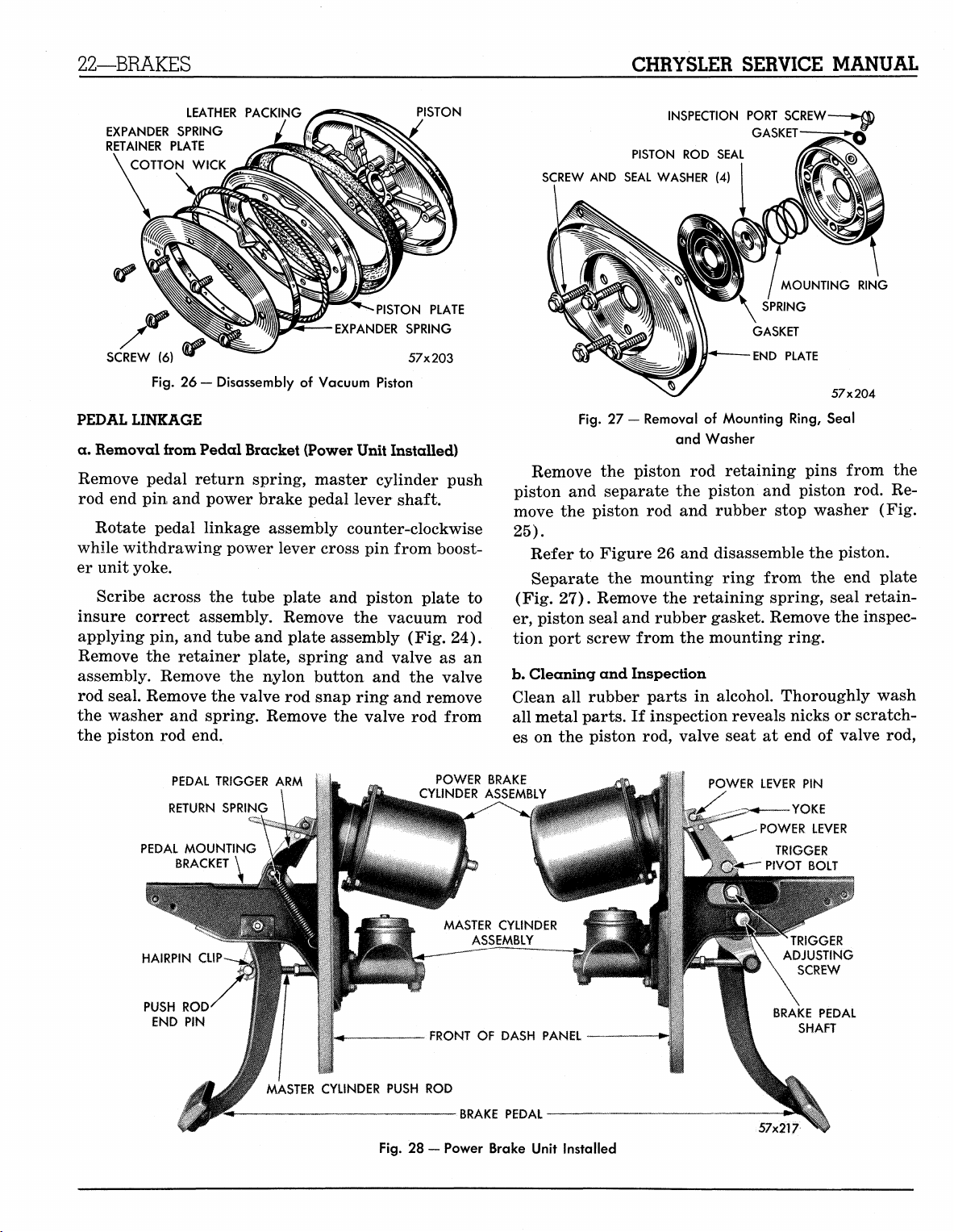
PEDAL LINKAGE
a. Removal from Pedal Bracket (Power Unit Installed)
Remove pedal return spring, master cylinder push
rod end pin and power brake pedal lever shaft.
Rotate pedal linkage assembly counter-clockwise
while withdrawing power lever cross pin from booster unit yoke.
Scribe across the tube plate and piston plate to
insure correct assembly. Remove the vacuum rod
applying pin, and tube and plate assembly (Fig. 24).
Remove the retainer plate, spring and valve as an
assembly. Remove the nylon button and the valve
rod seal. Remove the valve rod snap ring and remove
the washer and spring. Remove the valve rod from
the piston rod end.
INSPECTION PORT SCREW
GASKET
PISTON
ROD
SEAL
SCREW
AND
SEAL WASHER
Fig.
27 —
Removal
(4)
GASKET
END PLATE
of
Mounting Ring, Seal
and Washer
MOUNTING RING
SPRING
57x204
Remove the piston rod retaining pins from the
piston and separate the piston and piston rod. Remove the piston rod and rubber stop washer (Fig.
25).
Refer to Figure 26 and disassemble the piston.
Separate the mounting ring from the end plate
(Fig. 27). Remove the retaining spring, seal retainer, piston seal and rubber gasket. Remove the inspection port screw from the mounting ring.
b.
Cleaning and Inspection
Clean all rubber parts in alcohol. Thoroughly wash
all metal parts. If inspection reveals nicks or scratches on the piston rod, valve seat at end of valve rod,
PEDAL TRIGGER
RETURN SPRING
PEDAL MOUNTING
BRACKET
PUSH
ROD
END
PIN
!
^ . MASTER CYLINDER PUSH
ARM
\
POWER BRAKE
CYLINDER ASSEMBLY
MASTER CYLINDER
FRONT
ROD
Fig.
28 —
Power Brake Unit Installed
ASSEMBLY
OF
DASH PANEL
W
:
POWER LEVER
•——YOKE
POWER LEVER
TRIGGER
*~^" PIVOT BOLT
ADJUSTING
BRAKE PEDAL
MyMopar.com
PIN
TRIGGER
SCREW
SHAFT

CHRYSLER SERVICE MANUAL
ACCESSORY BELT DRIVES—23
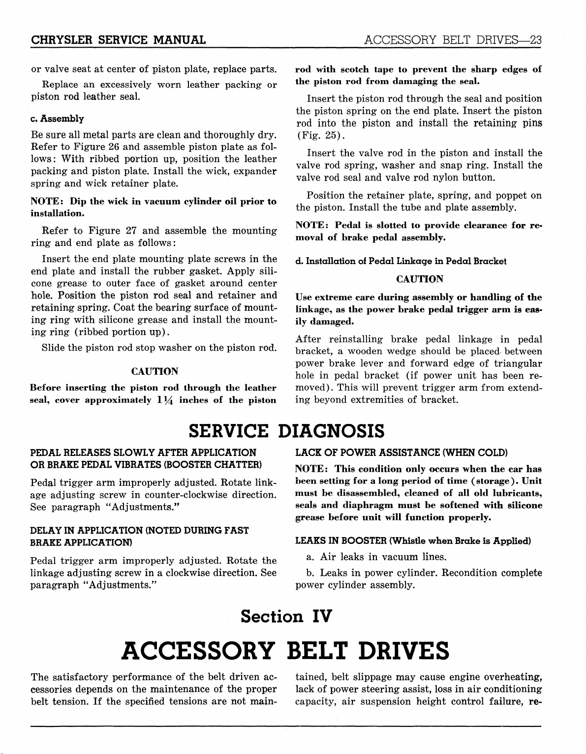
or valve seat at center of piston plate, replace parts.
Replace an excessively worn leather packing or
piston rod leather seal.
c.
Assembly
Be sure all metal parts are clean and thoroughly dry.
Refer to Figure 26 and assemble piston plate as follows:
With ribbed portion up, position the leather
packing and piston plate. Install the wick, expander
spring and wick retainer plate.
NOTE: Dip the wick in vacuum cylinder oil prior to
installation.
Refer to Figure 27 and assemble the mounting
ring and end plate as follows:
Insert the end plate mounting plate screws in the
end plate and install the rubber gasket. Apply sili-
cone grease to outer face of gasket around center
hole.
Position the piston rod seal and retainer and
retaining spring. Coat the bearing surface of mounting1 ring with silicone grease and install the mounting ring (ribbed portion up).
Slide the piston rod stop washer on the piston rod.
CAUTION
Before inserting the piston rod through the leather
seal, cover approximately 1*4 inches of the piston
rod with scotch tape to prevent the sharp edges of
the piston rod from damaging the seal.
Insert the piston rod through the seal and position
the piston spring on the end plate. Insert the piston
rod into the piston and install the retaining pins
(Fig. 25).
Insert the valve rod in the piston and install the
valve rod spring, washer and snap ring. Install the
valve rod seal and valve rod nylon button.
Position the retainer plate, spring, and poppet on
the piston. Install the tube and plate assembly.
NOTE: Pedal is slotted to provide clearance for re-
moval of brake pedal assembly.
d. Installation of Pedal Linkage in Pedal Bracket
CAUTION
Use extreme care during assembly or handling of the
linkage, as the power brake pedal trigger arm is easily damaged.
After reinstalling brake pedal linkage in pedal
bracket, a wooden wedge should be placed between
power brake lever and forward edge of triangular
hole in pedal bracket (if power unit has been removed). This will prevent trigger arm from extending beyond extremities of bracket.
SERVICE DIAGNOSIS
PEDAL RELEASES SLOWLY AFTER APPLICATION
OR BRAKE PEDAL VIBRATES (BOOSTER CHATTER)
Pedal trigger arm improperly adjusted. Rotate linkage adjusting screw in counter-clockwise direction.
See paragraph "Adjustments."
DELAY IN
BRAKE APPLICATION)
Pedal trigger arm improperly adjusted. Rotate the
linkage adjusting screw in a clockwise direction. See
paragraph ''Adjustments."
APPLICATION (NOTED DURING FAST
Section
ACCESSORY BELT DRIVES
The satisfactory performance of the belt driven accessories depends on the maintenance of the proper
belt tension. If the specified tensions are not main-
LACK OF POWER ASSISTANCE (WHEN COLD)
NOTE: This condition only occurs when the car has
been setting for a long period of time ( storage
must be disassembled, cleaned of all old lubricants,
seals and diaphragm must be softened with silicone
grease before unit will function properly.
LEAKS IN
a. Air leaks in vacuum lines.
b.
power cylinder assembly.
BOOSTER (Whistle when Brake is Applied)
Leaks in power cylinder. Recondition complete
).
Unit
IV
tained, belt slippage may cause engine overheating,
lack of power steering assist, loss in air conditioning
capacity, air suspension height control failure, re-
MyMopar.com
CHRYSLER SERVICE MANUAL
ACCESSORY BELT DRIVES—23
or valve seat at center of piston plate, replace parts.
Replace an excessively worn leather packing or
piston rod leather seal.
c.
Assembly
Be sure all metal parts are clean and thoroughly dry.
Refer to Figure 26 and assemble piston plate as follows:
With ribbed portion up, position the leather
packing and piston plate. Install the wick, expander
spring and wick retainer plate.
NOTE: Dip the wick in vacuum cylinder oil prior to
installation.
Refer to Figure 27 and assemble the mounting
ring and end plate as follows:
Insert the end plate mounting plate screws in the
end plate and install the rubber gasket. Apply sili-
cone grease to outer face of gasket around center
hole.
Position the piston rod seal and retainer and
retaining spring. Coat the bearing surface of mounting1 ring with silicone grease and install the mounting ring (ribbed portion up).
Slide the piston rod stop washer on the piston rod.
CAUTION
Before inserting the piston rod through the leather
seal, cover approximately 1*4 inches of the piston
rod with scotch tape to prevent the sharp edges of
the piston rod from damaging the seal.
Insert the piston rod through the seal and position
the piston spring on the end plate. Insert the piston
rod into the piston and install the retaining pins
(Fig. 25).
Insert the valve rod in the piston and install the
valve rod spring, washer and snap ring. Install the
valve rod seal and valve rod nylon button.
Position the retainer plate, spring, and poppet on
the piston. Install the tube and plate assembly.
NOTE: Pedal is slotted to provide clearance for removal of brake pedal assembly.
d. Installation of Pedal Linkage in Pedal Bracket
CAUTION
Use extreme care during assembly or handling of the
linkage, as the power brake pedal trigger arm is eas-
ily damaged.
After reinstalling brake pedal linkage in pedal
bracket, a wooden wedge should be placed between
power brake lever and forward edge of triangular
hole in pedal bracket (if power unit has been removed). This will prevent trigger arm from extending beyond extremities of bracket.
SERVICE DIAGNOSIS
PEDAL RELEASES SLOWLY AFTER APPLICATION
OR BRAKE PEDAL VIBRATES (BOOSTER CHATTER)
Pedal trigger arm improperly adjusted. Rotate linkage adjusting screw in counter-clockwise direction.
See paragraph "Adjustments."
DELAY IN
BRAKE APPLICATION)
Pedal trigger arm improperly adjusted. Rotate the
linkage adjusting screw in a clockwise direction. See
paragraph ''Adjustments."
APPLICATION (NOTED DURING FAST
Section
ACCESSORY BELT DRIVES
The satisfactory performance of the belt driven accessories depends on the maintenance of the proper
belt tension. If the specified tensions are not main-
LACK OF POWER ASSISTANCE (WHEN COLD)
NOTE: This condition only occurs when the car has
been setting for a long period of time ( storage
must be disassembled, cleaned of all old lubricants,
seals and diaphragm must be softened with silicone
grease before unit will function properly.
LEAKS IN
a. Air leaks in vacuum lines.
b.
power cylinder assembly.
BOOSTER (Whistle when Brake is Applied)
Leaks in power cylinder. Recondition complete
).
Unit
IV
tained, belt slippage may cause engine overheating,
lack of power steering assist, loss in air conditioning
capacity, air suspension height control failure, re-
MyMopar.com
24—ACCESSORY BELT DRIVES
CHRYSLER SERVICE MANUAL
duced generator charging rates, and greatly reduced
belt life. To avoid any such adverse effects, the following service procedure should be followed:
1.
Adjust all belts "in use"* to the specified belt
tension at new car preparation.
2.
Readjust all belts at the 2,000 mile inspection
and service.
3.
Check all belts by the deflection method at serv-
icing and readjust if needed,
4.
The new belt tension specifications should be
used on all new belt installations and the above procedure followed thereafter.
There are two methods by which belt tensions can
be properly established:
Torque Method — All generator and power steering
pump belts can be tightened to the specified tension
(see Tension Specifications that follow), by use of a
torque wrench. The generator belts are tensioned by
using a special tool C-3379, and torque wrench. The
power steering belts are tightened by inserting the
torque wrench in the square hole provided in the
bracket. Other belts can also be tightened by this
method if the adjusting bracket has a square hole.
To tighten belts by the torque method, loosen all
mounting bolts and apply the specified torque to the
accessory or idler. Tighten all mounting bolts while
the torque is applied to the accessory. If it is not possible to use the torque wrench because of clearance,
use an extension.
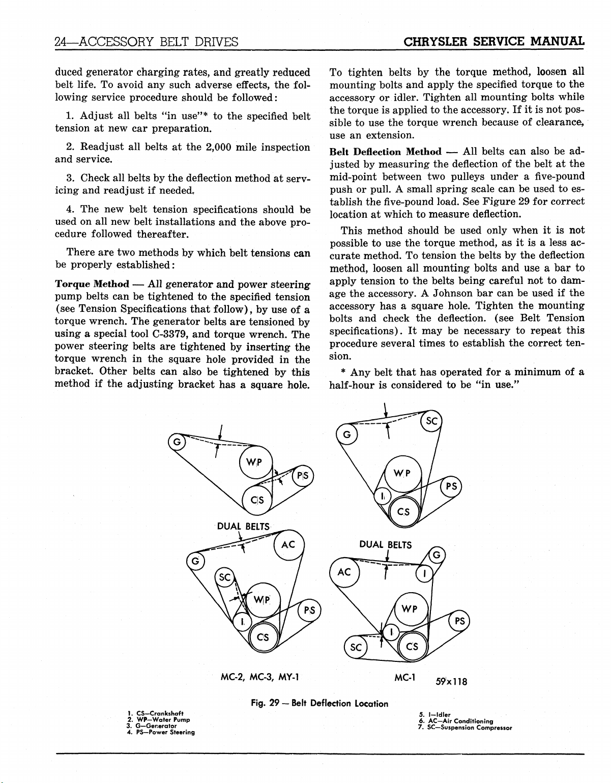
Belt Deflection Method — All belts can also be adjusted by measuring the deflection of the belt at the
mid-point between two pulleys under a five-pound
push or pull. A small spring scale can be used to establish the
five-pound
load. See Figure 29 for correct
location at which to measure deflection.
This method should be used only when it is not
possible to use the torque method, as it is a less accurate method. To tension the belts by the deflection
method, loosen all mounting bolts and use a bar to
apply tension to the belts being careful not to damage the accessory. A Johnson bar can be used if the
accessory has a square hole. Tighten the mounting
bolts and check the deflection, (see Belt Tension
specifications). It may be necessary to repeat this
procedure several times to establish the correct tension.
* Any belt that has operated for a minimum of a
half-hour is considered to be "in use."
1.
CS-Crankshaft
2.
WP-Water Pump
3. G—Generator
4. PS—Power Steering
MC-2,
MC-3, MY-1 MC-1
Fig.
29 — Belt Deflection Location
59xll8
5.
I—Idler
6. AC-Air Conditioning
7. SC—Suspension Compressor
MyMopar.com
CHRYSLER SERVICE MANUAL
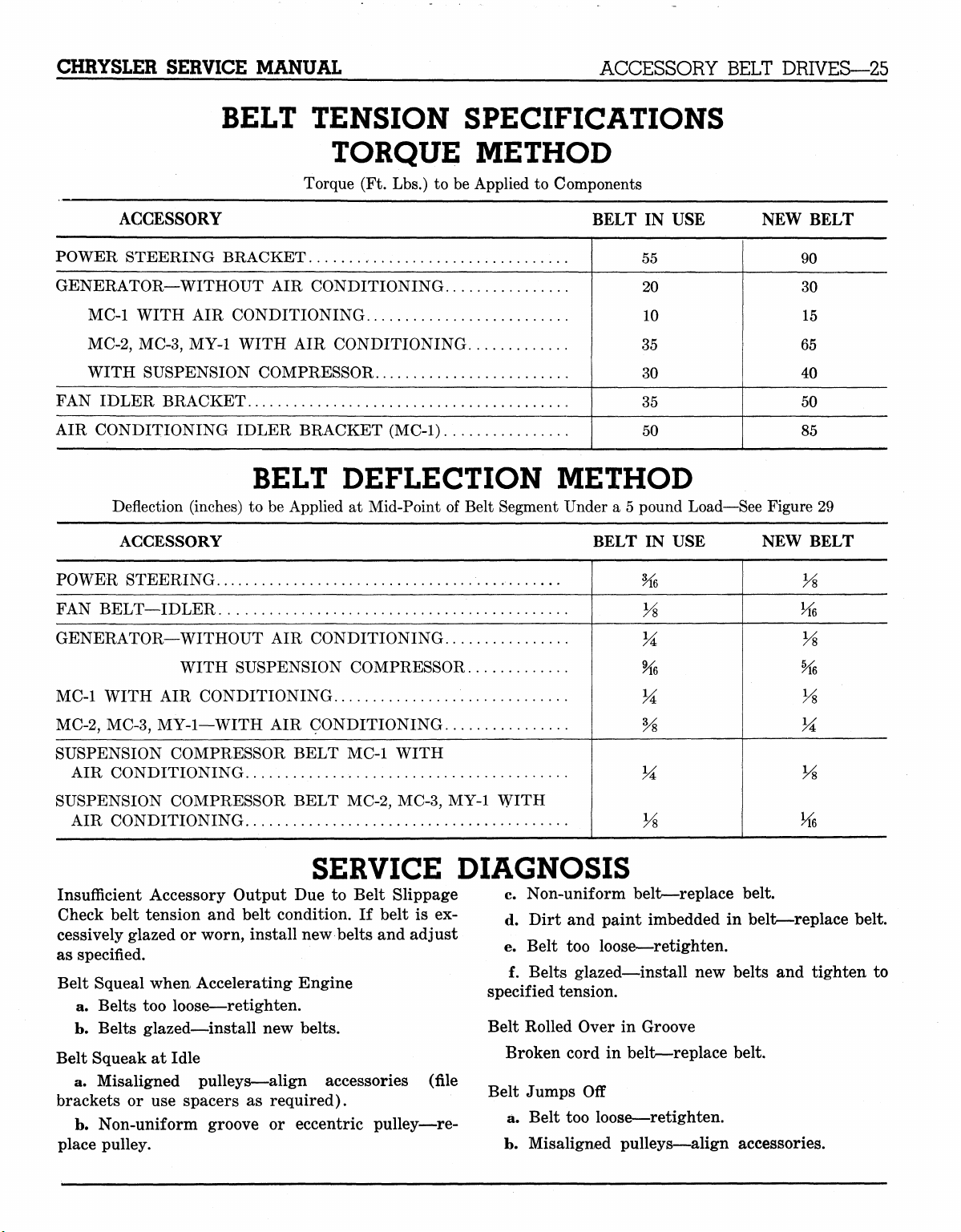
BELT TENSION SPECIFICATIONS
Torque (Ft. Lbs.) to be Applied to Components
ACCESSORY BELT DRIVES—25
TORQUE METHOD
ACCESSORY
POWER STEERING BRACKET
GENERATOR—WITHOUT AIR CONDITIONING
MC-1 WITH AIR CONDITIONING
MC-2,
MC-3, MY-1 WITH AIR CONDITIONING
WITH SUSPENSION COMPRESSOR
FAN IDLER BRACKET
AIR CONDITIONING IDLER BRACKET (MC-1)
BELT DEFLECTION METHOD
Deflection (inches) to be Applied at Mid-Point of Belt Segment Under a 5 pound Load—See Figure 29
ACCESSORY
POWER STEERING
FAN BELT—IDLER
GENERATOR—WITHOUT AIR CONDITIONING
WITH SUSPENSION COMPRESSOR
MC-1 WITH AIR CONDITIONING
MC-2,
MC-3, MY-1—WITH AIR CONDITIONING
SUSPENSION COMPRESSOR BELT MC-1 WITH
AIR CONDITIONING
SUSPENSION COMPRESSOR BELT MC-2, MC-3, MY-1 WITH
AIR CONDITIONING
BELT IN USE
55
20
10
35
30
35
50
NEW BELT
90
30
15
65
40
50
85
BELT IN USE NEW BELT
%,
Vs
VA
%>
Vs
Vs
Vs
Hi
Vs
%
Vs
M
Vs
Hi
SERVICE DIAGNOSIS
Insufficient Accessory Output Due to Belt Slippage
Check belt tension and belt condition. If belt is excessively glazed or worn, install new belts and adjust
as specified.
Belt Squeal when Accelerating Engine
a. Belts too loose—retighten.
b.
Belts glazed—install new belts.
Belt Squeak at Idle
a. Misaligned pulleys—align accessories
brackets or use spacers as required).
b.
Non-uniform groove or eccentric pulley—re-
place pulley.
(file
c. Non-uniform belt—replace belt.
d. Dirt and paint imbedded in belt—replace belt.
e. Belt too loose—retighten.
f. Belts glazed—install new belts and tighten to
specified tension.
Belt Rolled Over in Groove
Broken cord in belt—replace belt.
Belt Jumps Off
a. Belt too loose—retighten.
b.
Misaligned pulleys—align accessories.
MyMopar.com
26—COOLING SYSTEM
CHRYSLER SERVICE MANUAL
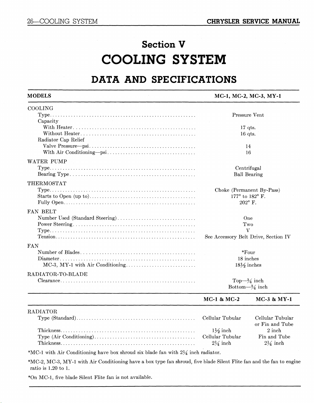
Section V
COOLING SYSTEM
DATA AND SPECIFICATIONS
MODELS MC-1, MC-2, MC-3, MY-1
COOLING
Type Pressure Vent
Capacity
With Heater 17 qts.
Without Heater 16 qts.
Radiator Cap Relief
Valve Pressure—psi 14
With Air Conditioning—psi 16
WATER PUMP
Type Centrifugal
Bearing Type Ball Bearing
THERMOSTAT
Type Choke (Permanent By-Pass)
Starts to Open (up to) 177° to 182° F.
Fully Open 202° F.
FAN BELT
Number Used (Standard Steering) One
Power Steering Two
Type V
Tension See Accessory Belt Drive, Section IV
FAN
Number of Blades , *Four
Diameter 18 inches
MC-3,
MY-1 with Air Conditioning 18J^ inches
RADIATOR-TO-BLADE
Clearance Top—% inch
Bottom—% inch
MC-1 & MG-2 MC-3 & MY-1
RADIATOR
Type (Standard) Cellular Tubular Cellular Tubular
or Fin and Tube
Thickness 1J/2 inch 2 inch
Type (Air Conditioning) Cellular Tubular Fin and Tube
Thickness 2^ inch 2lA inch
*MC-1 with Air Conditioning have box shroud six blade fan with 234 inch radiator.
*MC-2,
*On MC-1, five blade Silent Flite fan is not available.
MC-3, MY-1 with Air Conditioning have a box type fan shroud, five blade Silent Flite fan and the fan to engine
ratio is 1.20 to 1.
MyMopar.com
CHRYSLER SERVICE MANUAL
ELECTRICAL SYSTEM—27
COOLING SYSTEM
The cooling system servicing is the same for 1959
with the exception of the following: The capacity of
the radiator cooling system is 17 quarts with a heater and 16 quarts without a heater.
The radiator oil cooler located in the bottom of the
pan in the radiator tank has a new service proce-
dure.
Testing for Leaks
Remove the two oil cooler lines at the radiator. Con-
nect a pressure gauge to one cooler outlet. Connect
a source of air pressure with a shut-off valve (closed
Section VI
ELECTRICAL SYSTEM
DATA AND SPECIFICATIONS
BATTERY
position) to the other outlet. Do not use pipe sealers
since the sealer may get into transmission oil circuit.
Open valve slightly and admit air pressure not to
exceed 50 psi gauge reading, then close valve. If the
cooler and all fittings are leak
ing will remain constant.
When a leak is detected, remove radiator from car.
Remove radiator lower tank (soft solder). Test the
cooler with 50 psi air pressure in water to locate leak.
Repair the leak using silver solder. If necessary, have
a competent radiator repair shop repair the leak or
install a new cooler.
MG-1,
proof,
MG-2, MG-3, MY-1
the gauge read-
Voltage
Capacity
Terminal Ground
78 Plate 70 Amp Hour
12
Negative
STARTER
MC-1,
MC-2, MC-3, MY-1
Car Model Usage MDT-6002-1770712
Starter Model „ MDT-6002
Voltage 12
No.
of Fields 4
No.
of Poles 4
Brushes 4
Spring Tension 32 to 48 Ounces
Drive Solenoid Shift Overrunning Clutch
End Play .005" Minimum
Free Running Test
Voltage 11
Amperage Draw 80 Amps Minimum
Minimum Speed rpm 3800 Minimum
Stall Torque Test
Torque Foot-Pounds 8.5
Voltage 4
Amperage Draw 350
Pinion to Housing .070" to .120"
Clearance Between Pinion Stop
(with Armature End Play removed)
MyMopar.com
 Loading...