


CHRYSLER
CORPORATION
1993 SERVICE MANUAL
CONCORDE
INTREPID
VISION
To order the special service tools used and illustrated, please refer to the instructions on inside back cover.
NO PART OF THIS PUBLICATION MAY BE REPRODUCED, STORED IN A RETRIEVAL SYSTEM, OR TRANSMITTED, IN ANY FORM OR BY ANY MEANS, ELECTRONIC, MECHANICAL, PHOTOCOPYING, RECORDING, OR OTHERWISE, WITHOUT THE PRIOR WRITTEN PERMISSION OF CHRYSLER CORPORATION.
Chrysler Corporation reserves the right to make changes in design or to make additions to or improvements in its products without imposing any obligations upon itself to install them on its products previously manufactured.
Litho in U.S.A. Copyright © 1992 Chrysler Corporation 15M0692
NEXT PAGE ©
FOREWORD
The information contained in this service manual has been prepared for the professional automotive technician involved in daily repair operations. This manual does not cover theory of operation, which is addressed in service training material. Information describing the operation and use of standard and optional equipment is included in the Owner's Manual provided with the vehicle.
Information in this manual is divided into groups. These groups contain general information, diagnosis, testing, adjustments, removal, installation, disassembly, and assembly procedures for the components.
The Component and System Index of this manual identifies the correct group for the component or system to be serviced. In addition, a Service Manual Comment form is included at the rear of this manual. Use the form to provide Chrysler Corporation with your comments and suggestions.
To assist in locating a group title page, use the Group Tab Locator on the following page. The solid bar after the group title is aligned to a solid tab on the first page of each group. The first page of the group has a contents section that lists major topics within the group.
Throughout this manual, the vehicle family code, LH, is used when descriptions or procedures apply to all three models, Concorde, Intrepid and Vision.
Tightening torques are provided as a specific value throughout this manual. This value represents the midpoint of the acceptable engineering torque range for a given fastener application. These torque values are intended for use in service assembly and installation procedures using the correct OEM fasteners. When replacing fasteners, always use the same type (part number) fastener as removed.
Chrysler Corporation reserves the right to change testing procedures, specifications, diagnosis, repair methods, or vehicle wiring at any time without prior notice or incurring obligation.
NOTE: The acronyms, terminology and nomenclature used to identify emissions related components in this manual may have changed from prior publications. These new terms are in compliance with S.A.E. recommended practice J1930. This terminology standard (J1930) is required to comply with the 1993 California Air Research Board (CARB) requirements.
NEXT PAGE ©
|
GROUP TAB LOCATOR |
|
|
||
|
|
|
|
|
|
|
|
|
|
|
|
|
Introduction |
|
|
|
|
|
|
|
|
|
|
|
|
|
|
|
|
0 |
Lubrication and Maintenance |
|
|
|
|
|
|
|
|
|
|
|
|
|
|
|
|
2 |
Suspension and Driveshaft |
|
|
|
|
|
|
|
|
|
|
|
|
|
|
|
|
5 |
Brakes |
|
|
|
|
|
|
|
|
|
|
|
|
|
|
|
|
7 |
Cooling System |
|
|
|
|
|
|
|
|
|
|
|
|
|
|
|
|
8 |
Electrical |
|
|
|
|
|
|
|
|
|
|
|
|
|
|
|
|
9 |
Engines |
|
|
|
|
|
|
|
|
||
|
|
|
|||
11 |
Exhaust System and Intake Manifold |
|
|
||
|
|
|
|
|
|
|
|
|
|
|
|
13 |
Frame and Bumpers |
|
|
|
|
|
|
|
|
|
|
|
|
|
|
|
|
14 |
Fuel System |
|
|
|
|
|
|
|
|
|
|
|
|
|
|
|
|
19 |
Steering |
|
|
|
|
|
|
|
|
|
|
|
|
|
|
|
|
21 |
Transaxle |
|
|
|
|
|
|
|
|
|
|
|
|
|
|
|
|
22 |
Wheels and Tires |
|
|
|
|
|
|
|
|
|
|
|
|
|
|
|
|
23 |
Body Components |
|
|
|
|
|
|
|
|
|
|
|
|
|
|
|
|
24 |
Heating and Air Conditioning |
|
|
|
|
|
|
|
|
|
|
|
|
|
|
|
|
25 |
Emission Control Systems |
|
|
|
|
|
|
|
|
|
|
|
|
|
|
|
|
|
Component and System Index |
|
|
|
|
|
|
|
|
||
|
|
|
|||
Service Manual Comment Forms |
(Rear of Manual) |
|
|||
|
|
|
|
|
|

LUBRICATION AND MAINTENANCE 0 - 1
LUBRICATION AND MAINTENANCE
CONTENTS
|
page |
|
page |
CHASSIS AND BODY . . . . . . . . . . . . . . . . . . . |
. 15 |
ENGINE . . . . . . . . . . . . . . . . . . . . . . . . . . . . . . |
. . 7 |
DRIVETRAIN . . . . . . . . . . . . . . . . . . . . . . . . . . |
. 13 |
GENERAL INFORMATION . . . . . . . . . . . . . . . . |
. . 1 |
GENERAL INFORMATION
INDEX
|
page |
|
page |
Classification of Lubricants . . . . . . . . . . . . . . . . |
. . 1 |
Jump Starting Procedure . . . . . . . . . . . . . . . . . . |
. . 4 |
Fluid Capacities . . . . . . . . . . . . . . . . . . . . . . . . |
. . 2 |
Parts and Lubricant Recommendations . . . . . . . |
. . 1 |
Fuel Usage . . . . . . . . . . . . . . . . . . . . . . . . . . . . |
. . 1 |
Parts Requiring No Lubrication . . . . . . . . . . . . . |
. . 2 |
Hoisting Recommendations . . . . . . . . . . . . . . . . |
. . 4 |
Severe Service . . . . . . . . . . . . . . . . . . . . . . . . . |
. . 1 |
Introduction . . . . . . . . . . . . . . . . . . . . . . . . . . . . |
. . 1 |
Towing Recommendations . . . . . . . . . . . . . . . . . |
. . 5 |
INTRODUCTION
Chrysler Corporation has compiled recommended lubrication and maintenance schedules and procedures to help reduce premature wear or failure over a broad range of operating conditions. When selecting the proper maintenance schedule, the climate and operating conditions must be considered. A vehicle subjected to severe usage requires more frequent service than a vehicle used for general transportation.
PARTS AND LUBRICANT RECOMMENDATIONS
When service is required, Chrysler Corporation recommends that only Mopart brand parts, lubricants and chemicals be used. Mopar provides the best engineered products for servicing Chrysler Corporation vehicles.
SEVERE SERVICE
If a vehicle is operated under any of the following conditions, it is considered severe service.
²Extremely dusty areas.
²50% or more of vehicle operation in 32°C (90°F) or higher temperatures.
²Prolonged idling (such as, vehicle operation in stop and go traffic).
²Frequent short running periods. Not allowing engine to warm to operating temperatures.
²Police or taxi usage.
FUEL USAGE
All Chrysler Corporation engines require the use of unleaded fuel to reduce exhaust emissions. See Engine section of this group and Group 14, Fuel for fuel recommendations.
CLASSIFICATION OF LUBRICANTS
Only lubricants that are endorsed by the following organization should be used to service a Chrysler Corporation vehicle.
²Society of Automotive Engineers (SAE)
²American Petroleum Institute (API)
²National Lubricating Grease Institute (NLGI)
ENGINE OIL
SAE GRADE RATING INDICATES ENGINE OIL VISCOSITY
²SAE 30 = single grade engine oil.
²SAE 5W-30 = multiple grade engine oil.
API QUALITY CLASSIFICATION.
²SG service engine oil is a high quality crankcase lubricant designed for use in all naturally aspirated engines.
²SG/CD service engine oil is a high performance crankcase lubricant designed for use in all gasoline or diesel engines.
GEAR LUBRICANTS
SAE ratings also apply to multiple grade gear lubricants. In addition, API classification defines the lubricants usage.
0 - 2 LUBRICATION AND MAINTENANCE
LUBRICANTS AND GREASES
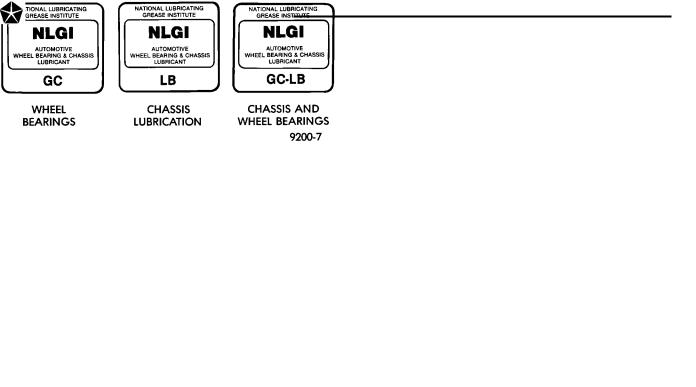
Lubricating grease is rated for quality and usage by the NLGI. All approved products have the NLGI symbol on the label.
At the bottom NLGI symbol is the usage and quality identification letters. Wheel bearing lubricant is identified by the letter ``G''. Chassis lubricant is identified by the letter ``L''. The letter following the usage letter indicates the quality of the lubricant. The following symbols indicate the highest quality.
NLGI SYMBOL
PARTS REQUIRING NO LUBRICATION
Many components on a Chrysler Corporation vehicle require no periodic maintenance. Some components are sealed and permanently lubricated. Rubber
bushings can deteriorate or limit damping ability if lubricated. The following list of components require no lubrication:
²Air Pump
²Generator Bushings
²Drive Belts
²Drive Belt Idler/Tensioner Pulley
²Wheel Bearings
²Rubber Bushings
²Starter Bearings/Bushings
²Suspension Strut Bearings
²Throttle Control Cable
²Throttle Linkage
²Water Pump Bearings
FLUID CAPACITIES
Fuel Tank.............................................. |
68L (18 |
gal.) |
Engine Oil |
|
|
3.3L........................................................... |
4.7L (5 qts.) |
|
3.5L........................................................ |
5.2L (5.5 |
qts.) |
Cooling System |
|
|
3.3L................................................ |
10.74L (10.17 |
qts.) |
3.5L................................................ |
12.46L (11.80 |
qts.) |
Includes heater and coolant pressure bottle |
|
|
Transmission ...................................... |
9.4L (9.9 qts.) |
|
Differential................................................. |
95L (1 qt) |
|

LUBRICATION AND MAINTENANCE 0 - 3
0 - 4 LUBRICATION AND MAINTENANCE
JUMP STARTING PROCEDURE
WARNING: REVIEW ALL SAFETY PRECAUTIONS AND WARNINGS IN GROUP 8A, BATTERY/STARTING/CHARGING SYSTEMS DIAGNOSTICS.
DO NOT JUMP START A FROZEN BATTERY, PERSONAL INJURY CAN RESULT.
DO NOT JUMP START WHEN BATTERY INDICATOR DOT IS YELLOW OR BRIGHT COLOR.
DO NOT ALLOW JUMPER CABLE CLAMPS TO TOUCH EACH OTHER WHEN CONNECTED TO A BOOSTER SOURCE.
DO NOT USE OPEN FLAME NEAR BATTERY. REMOVE METALLIC JEWELRY WORN ON HANDS
OR WRISTS TO AVOID INJURY BY ACCIDENTAL ARCHING OF BATTERY CURRENT.
WARNING: WHEN USING A HIGH OUTPUT BOOSTING DEVICE, DO NOT ALLOW DISABLED VEHICLE'S BATTERY TO EXCEED 16 VOLTS. PERSONAL INJURY OR DAMAGE TO ELECTRICAL SYSTEM CAN RESULT.
CAUTION: When using another vehicle as a booster, do not allow vehicles to touch. Electrical systems can be damaged on either vehicle.
TO JUMP START A DISABLED VEHICLE:
(1) Raise hood on disabled vehicle and visually inspect engine compartment for:
²Battery cable clamp condition, clean if necessary.
²Frozen battery.
²Yellow or bright color test indicator, if equipped.
²Low battery fluid level.
²Generator drive belt condition and tension.
²Fuel fumes or leakage, correct if necessary.
CAUTION: If the cause of starting problem on disabled vehicle is severe, damage to booster vehicle charging system can result.
(2)When using another vehicle as a booster source, turn off all accessories, place gear selector in park or neutral, set park brake or equivalent and operate engine at 1200 rpm.
(3)On disabled vehicle, place gear selector in park or neutral and set park brake or equivalent. Turn OFF all accessories (Keyless Entry system must be turned OFF manually).
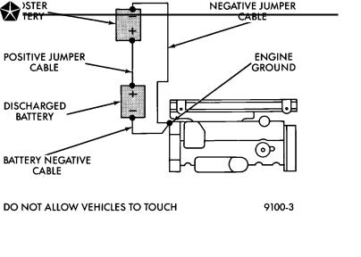
(4)Connect jumper cables to booster battery. RED clamp to positive terminal (+). BLACK clamp to negative terminal (-). DO NOT allow clamps at opposite end of cables to touch, electrical arc will result (Fig. 1). Review all warnings in this procedure.
(5)On disabled vehicle, connect RED jumper cable clamp to positive (+) terminal. Connect BLACK jumper cable clamp to engine ground as close to the ground cable attaching point as possible (Fig. 1).
Fig. 1 Jumper Cable Clamp Connections
CAUTION: Do not crank starter motor on disabled vehicle for more than 15 seconds, starter will overheat and could fail.
(6) Allow battery in disabled vehicle to charge to at least 12.4 volts (75% charge) before attempting to start engine. If engine does not start within 15 seconds, stop cranking engine and allow starter to cool (15 min.), before cranking again.
DISCONNECT CABLE CLAMPS AS FOLLOWS:
²Disconnect BLACK cable clamp from engine ground on disabled vehicle.
²When using a Booster vehicle, disconnect BLACK cable clamp from battery negative terminal. Disconnect RED cable clamp from battery positive terminal.
²Disconnect RED cable clamp from battery positive terminal on disabled vehicle.
HOISTING RECOMMENDATIONS
Refer to Owner's Manual provided with vehicle for proper emergency jacking procedures.
WARNING: THE HOISTING AND JACK LIFTING POINTS PROVIDED ARE FOR A COMPLETE VEHICLE. WHEN THE ENGINE OR REAR SUSPENSION IS REMOVED FROM A VEHICLE, THE CENTER OF GRAVITY IS ALTERED MAKING SOME HOISTING CONDITIONS UNSTABLE. PROPERLY SUPPORT OR SECURE VEHICLE TO HOISTING DEVICE WHEN THESE CONDITIONS EXIST.
CAUTION: Do not position hoisting device on suspension components, damage to vehicle can result.
TO HOIST OR JACK VEHICLE SEE FIG. 2
Fig. 2 Hoisting and Jacking Points
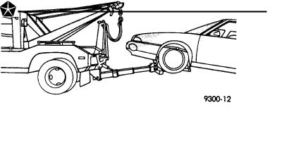
TOWING RECOMMENDATIONS
RECOMMENDED TOWING EQUIPMENT
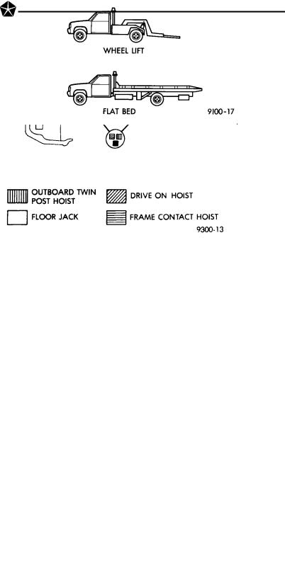
To avoid damage to bumper fascia and air dams use of a wheel lift or flat bed towing device (Fig. 3) is recommended. When using a wheel lift towing device, be sure the rear end of disabled vehicle has at least 100 mm (4 in.) ground clearance. If minimum ground clearance cannot be reached, use a towing dolly. If a flat bed device is used, the approach angle should not exceed 15 degrees.
Fig. 3 Recommended Towing Devices
GROUND CLEARANCE
CAUTION: If vehicle is towed with wheels removed, install lug nuts to retain brake drums or rotors.
A towed vehicle should be raised until lifted wheels are a minimum 100 mm (4 in) from the ground. Be sure there is adequate ground clearance at the oppo-
LUBRICATION AND MAINTENANCE 0 - 5
site end of the vehicle, especially when towing over rough terrain or steep rises in the road. If necessary, remove the wheels from the lifted end of the vehicle and lower the vehicle closer to the ground, to increase the ground clearance at the opposite end of the vehicle. Install lug nuts on wheel attaching studs to retain braking discs.
SAFETY PRECAUTIONS
The following safety precautions must be considered when preparing for and during a vehicle towing operation:
²Do NOT tow vehicle with front wheels on the ground. The transaxle can be damaged.
²Secure loose and protruding parts from a disabled vehicle.
²Always use a safety chain system that is independent of the lifting and towing equipment.
²Do not allow any of the towing equipment to contact the fuel tank of the vehicle being towed.
²Do not go under the vehicle while it is lifted by the towing equipment.
²Do not allow passengers to ride in a vehicle being towed.
²Always observe all state and local laws pertaining to warning signals, night illumination,speed, etc.
²Do not attempt a towing operation that could jeopardize the operator, bystanders or other motorists.
²Do not exceed a towing speed of 48 km/h (30mph).
²Avoid towing distances of more than 24 km (15miles), whenever possible.
²Never attach tow chains or a tow sling to the bumper, steering linkage, or constant velocity joints.
TIE DOWN LOCATIONS FOR FLAT BED TOWING
There are three reinforced elongated holes on each side of the vehicle designed to serve as hold down locations. These locations can safely hold the vehicle to the towing device using T or R-hooks.
²Bottom of the front frame rail forward of the engine cradle.
²Bottom of the forward torque box between the front frame rail and the rocker panel.
²Bottom of the rearward torque box forward of the rear wheel.
FRONT TOWING PROCEDURES
CAUTION: Do Not tow vehicle from the front with sling type towing device. Damage to bumper fascia will result.
Always tow vehicle with front wheels off the ground as shown (Fig. 4).
Use a flat bed towing device when wheel lift towing device is not available.
0 - 6 LUBRICATION AND MAINTENANCE
REAR TOWING PROCEDURES
CAUTION: Do not tow vehicle with the rear end lifted.
If damage to the vehicle prevents front towing, use a flat bed towing device.
CAUTION: Do not push the vehicle with another vehicle as damage to the bumper facia and transaxle can result.
Fig. 4 Towing
|
|
|
|
LUBRICATION AND MAINTENANCE |
0 - 7 |
|
|
|
|
||
|
|
ENGINE |
|
||
|
|
INDEX |
|
||
|
|
page |
|
|
page |
Engine Oil Filter . . . . . . . . . . . . . . . . . . . . . . . . |
. . 8 |
Engine Oil . . . . . . . . . . . . . . . . . . . . . . . . . . |
. . . . . 7 |
||
Battery . . . . . . . . . . . . . . . . . . . . . . . . . . . . . . . |
. 12 |
Frequency of Engine Oil and Filter Changes |
. . . . . 7 |
||
Crankcase Ventilation System . . . . . . . . . . . . . . |
. 10 |
Fuel Filter . . . . . . . . . . . . . . . . . . . . . . . . . . |
. . . . 11 |
||
Drive Belts . . . . . . . . . . . . . . . . . . . . . . . . . . . . |
. 11 |
Fuel Recommendations . . . . . . . . . . . . . . . . |
. . . . 11 |
||
Emission Control System . . . . . . . . . . . . . . . . . . |
. 11 |
Ignition Cables . . . . . . . . . . . . . . . . . . . . . . . |
. . . 11 |
||
Engine Air Cleaner . . . . . . . . . . . . . . . . . . . . . . |
. 10 |
Rubber and Plastic Component Inspection . . . |
. . . 12 |
||
Engine Cooling System . . . . . . . . . . . . . . . . . . . |
. . 9 |
Spark Plugs . . . . . . . . . . . . . . . . . . . . . . . . . |
. . . 11 |
||
FREQUENCY OF ENGINE OIL AND FILTER CHANGES
ENGINE OIL
Road conditions as well as your kind of driving affect the interval at which your oil should be changed. Check the following to determine if any apply to you:
²Frequent short trip driving less than 8 kilometers (5 miles)
²Frequent driving in dusty conditions
²Frequent trailer towing
²Extensive idling (such as vehicle operation in stop and go traffic)
²More than 50% of your driving is at sustained high speeds during hot weather, above 32°C (90°F)
If any of these apply to you then change your engine oil every 4 800 kilometers (3,000 miles) or 3 months, whichever comes first.
If none of these apply to you then change your oil every 12 000 kilometers (7,500 miles) or 6 months, whichever comes first.
If none of these apply and the vehicle is in commercial type service such as, Police, Taxi or Limousine used for highway driving of 40 kilometers (25 miles) or more between stations, the engine oil should be changed every 8 000 kilometers (5,000 miles) or 6 months.
OIL FILTER
The engine oil filter should be replaced with a new filter at every second oil change.
ENGINE OIL
WARNING: NEW OR USED ENGINE OIL CAN BE IRRITATING TO THE SKIN. AVOID PROLONGED OR REPEATED SKIN CONTACT WITH ENGINE OIL. CONTAMINANTS IN USED ENGINE OIL, CAUSED BY INTERNAL COMBUSTION, CAN BE HAZARDOUS TO YOUR HEALTH. THOROUGHLY WASH EXPOSED SKIN WITH SOAP AND WATER.
DO NOT WASH SKIN WITH GASOLINE, DIESEL FUEL, THINNER, OR SOLVENTS, HEALTH PROBLEMS CAN RESULT.
DO NOT POLLUTE, DISPOSE OF USED ENGINE OIL PROPERLY. CONTACT YOUR DEALER OR GOVERNMENT AGENCY FOR LOCATION OF COLLECTION CENTER IN YOUR AREA.
BREAK-IN PERIOD
CAUTION: Wide open throttle operation in low gears, before engine break-in period is complete, can damage engine.
On a Chrysler Corporation vehicle an extended break-in period is not required. Driving speeds of not over 80-90 km/h (50-55 mph) for the first 100 km (60 miles) is recommended. Hard acceleration and high engine rpm in lower gears should be avoided.
SELECTING ENGINE OIL
CAUTION: Do not use non-detergent or straight mineral oil when adding or changing crankcase lubricant. Engine or Turbocharger failure can result.
The factory fill engine oil is a high quality, energy conserving, crankcase lubricant. The Recommended SAE Viscosity Grades chart defines the viscosity grades that must be used based on temperature in the region where vehicle is operated and optional equipment.
Chrysler Corporation recommends that Mopar motor oil, or equivalent, be used when adding or changing crankcase lubricant. The API symbol (Fig. 1) on the container indicates the viscosity grade, quality and fuel economy ratings of the lubricant it contains. Use ENERGY CONSERVING II motor oil with API SERVICE SG or SG/CD classification.
²SG service engine oil is a high quality crankcase lubricant designed for use in all naturally aspirated engines.
²SG/CD service engine oil is a high quality crankcase lubricant designed for use in most naturally aspirated and turbocharged gasoline or diesel engines.
²SAE 5W-30 engine oil is recommended for use in 3.3L engines in temperatures below 38°C (100°F) to
0 - 8 LUBRICATION AND MAINTENANCE
reduce low temperature cranking effort. SAE 5W-30 is recommended for use in 3.5L engines in temperatures below 0°C (32°F). SAE 5W-30 engine oil is NOT recommended for use in 3.5L engines in temperatures above 0°C (32°F).
² SAE 10W-30 engine oil is recommended for use in 3.5L engine in temperatures above -18°C (0°F).
RECOMMENDED VISCOSITY GRADES
Fig. 1 API Symbol
ENGINE OIL ADDITIVES
Chrysler Corporation recommends that Mopar Engine Oil Supplement or equivalent be used when friction and corrosion reducing materials added to the crankcase lubricant is desired.
CRANKCASE OIL LEVEL INSPECTION
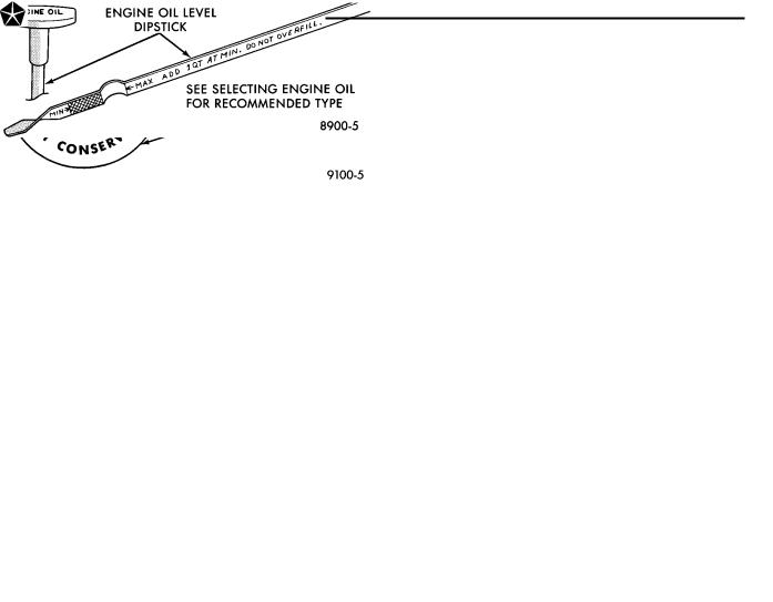
CAUTION: Do not overfill crankcase with engine oil, oil foaming and oil pressure loss can result.
Inspect engine oil level approximately every 800 kilometers (500 miles). Position vehicle on level surface. With engine OFF, allow enough time for oil to settle to bottom of crankcase, remove engine oil level indicator (dipstick) and wipe clean. Install dipstick and verify it is seated in the tube. Remove dipstick, with handle above tip, take oil level reading (Fig. 2). Add oil only if level is below MIN or ADD mark on dipstick.
ENGINE OIL CHANGE
Change engine oil at mileage and time intervals described in Lubrication and Maintenance Schedules.
Fig. 2 Oil Level Indicator DipstickÐTypical
TO CHANGE ENGINE OIL:
(1)Position the vehicle on a level surface.
(2)Hoist and support vehicle on safety stands. Refer to Hoisting and Jacking Recommendations in this group.
(3)Place a suitable 3.8 liter (4 qt.) drain pan under crankcase drain.
(4)Remove drain plug from crankcase and allow oil to drain into pan. Inspect drain plug threads for stretching or other damage. Replace drain plug and gasket if damaged.
(5)Install drain plug in crankcase.
(6)Lower vehicle and fill crankcase with specified type and amount of engine oil described in this section.
(7)Start engine and inspect for leaks.
(8)Stop engine and inspect oil level.
ENGINE OIL FILTER
SELECTING OIL FILTER
Chrysler Corporation recommends a Mopar or equivalent oil filter be used when replacement is required. A replacement filter must be designed to withstand 1756 kPa (256 psi) of internal pressure.
OIL FILTER REMOVAL
(1)Position a drain pan under the oil filter.
(2)Using a suitable oil filter wrench (Fig. 3) loosen filter.
(3)When filter separates from adapter nipple, tip gasket end upward to minimize oil spill. Remove filter from vehicle.
(4)With a wiping cloth, clean the gasket sealing surface (Fig. 4) of oil and grime. Wipe off oil residue from below oil filter adapter.
OIL FILTER INSTALLATION:
(1)Lightly lubricate oil filter gasket with engine oil or chassis grease.
(2)Thread filter onto adapter nipple. When gasket makes contact with sealing surface, tighten filter one full turn. If necessary use a filter wrench, do not over tighten.
(3)Add oil, verify crankcase oil level and start engine. Inspect for oil leaks.
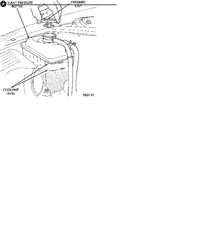
Fig. 3 Remove Oil Filter
Fig. 4 Install Oil Filter
ENGINE COOLING SYSTEM
WARNINGS AND PRECAUTIONS
WARNING: ANTIFREEZE IS AN ETHYLENE GLYCOL BASE COOLANT AND IS HARMFUL IF SWALLOWED OR INHALED. IF SWALLOWED, DRINK TWO GLASSES OF WATER AND INDUCE VOMITING. IF INHALED, MOVE TO FRESH AIR AREA. SEEK MEDICAL ATTENTION IMMEDIATELY. DO NOT STORE IN OPEN OR UNMARKED CONTAINERS. WASH SKIN AND CLOTHING THOROUGHLY AFTER COMING IN CONTACT WITH ETHYLENE GLYCOL. KEEP OUT OF REACH OF CHILDREN.
DISPOSE OF GLYCOL BASE COOLANT PROPERLY, CONTACT YOUR DEALER OR GOVERNMENT AGENCY FOR LOCATION OF COLLECTION CENTER IN YOUR AREA.
DO NOT OPEN A COOLING SYSTEM WHEN THE ENGINE IS AT RUNNING TEMPERATURE, PERSONAL INJURY CAN RESULT.
AVOID RADIATOR COOLING FAN WHEN ENGINE COMPARTMENT RELATED SERVICE IS PERFORMED, PERSONAL INJURY CAN RESULT.
CAUTION: Do not use straight antifreeze as engine coolant, inadequate engine running temperatures can result.
LUBRICATION AND MAINTENANCE 0 - 9
Do not operate vehicle without proper concentration of recommended ethylene glycol coolant, high running temperatures and cooling system corrosion can result.
The engine cooling system will develop internal pressure of 97 to 123 kPa (14 to 18 psi) at normal operating temperature. Allow the vehicle approximately one half hour to cool off before opening the cooling system. As an indicator of pressure, squeeze the upper radiator hose between index finger and thumb. If it collapses with little effort the system would have low internal pressure and should be safe to open to the first safety notch of the coolant pressure bottle cap. Refer to Group 7, Cooling System.
COOLING SYSTEM INSPECTION
Coolant level (Fig. 5) should be inspected when other engine compartment service is performed or when coolant leak is suspected. Coolant pressure bottle level should read between the MIN and MAX marks, located on the side of pressure bottle, when the engine is at normal operating temperature. Cooling system freeze protection should be tested at the onset of the winter season or every 12 months. Service is required if coolant is low, contaminated, rusty or freeze protection is inadequate. To properly test cooling system, see Group 7, Cooling System.
Fig. 5 Coolant Pressure Bottle
The cooling system factory fill is a mixture of 50% Glycol base antifreeze with silicate inhibitor and 50% water. Using a suitable hydrometer, measure antifreeze concentration in the coolant pressure bottle when the engine is cool. If the cooling system has recently been serviced, allow coolant to circulate for at
0 - 10 LUBRICATION AND MAINTENANCE
least 20 minutes before taking hydrometer reading. Properly mixed coolant will protect the cooling system to -37°C (-35°F). If the freeze protection is above -28°C (-20°F), drain enough coolant from the cooling system to allow room to add antifreeze to achieve adequate protection. A mix table on the coolant container indicates the amount of antifreeze required to winterize the cooling system based on the capacity, see Capacity Chart in General Information section of this group.
SELECTING ANTIFREEZE
Chrysler Corporation recommends Mopar Antifreeze/Summer Coolant, or equivalent be used to winterize and protect cooling system.
PRESSURE CAP
The pressure cap must be secure for the engine cooling system to perform properly. Inspect and test pressure cap when cooling system service is performed or when a problem is suspected.
COOLING SYSTEM SERVICE
The cooling system should be drained, flushed and filled with the proper coolant mixture at the intervals described in the Lubrication and Maintenance Schedules. Refer to General Information section of this group. For proper service instructions see Group 7, Cooling System.
ENGINE AIR CLEANER
The engine air cleaner should be serviced at the intervals described in the Lubrication and Maintenance Schedules. Refer to General Information section of this group. Additional information can be found in Group 14, Fuel System and Group 25, Emission System. Inspect all air cleaner hoses or tubes for damage or leaks when other engine compartment service is performed. Replace faulty components.
AIR CLEANER SERVICE
CAUTION: The air cleaner cover must be installed properly for the emissions system and engine controller to function correctly.
Do not immerse paper air filter element or temperature sensor in cleaning solvents, damage can result.
TO SERVICE AIR CLEANER
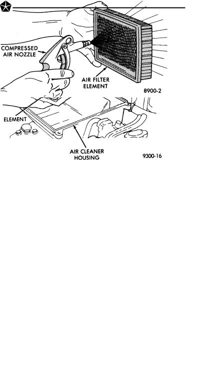
(1)Raise hood of vehicle and inspect all air cleaner components for damage or improper attachment.
(2)Remove air cleaner lid (Fig. 6).
(3)Remove paper air filter element from air cleaner body. Hold a shop light on throttle body side of element. Inspect air intake side of element. If light is visible through element, blow dust from element (Fig. 7) and reuse. If element is saturated with oil or
light is not visible, replace filter. If element is saturated with oil, perform crankcase ventilation system tests. Refer to Group 25, Emission Control Systems for proper procedure.
(4) Clean inside of air cleaner lid and body with vacuum or compressed air. If oily, wash with solvent.
To Install, reverse the preceding operation.
Fig. 6 Air Cleaner
Fig. 7 Cleaning Air Filter Element
CRANKCASE VENTILATION SYSTEM
Engine crankcase pressure and emissions are vented into combustion chambers through the positive crankcase ventilation (PCV) system (Fig. 8 or 9). The PCV system should have enough volume to overcome crankcase pressure created by piston backwash. If a PCV system becomes plugged, the crankcase pressure will increase and force engine oil past the piston rings creating oil consumption. Blockage of PCV system can occur at the vacuum source coupling, PCV valve or a collapsed hose.
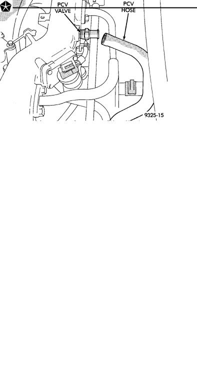
Chrysler Corporation recommends that a PCV valve not be cleaned. A new Mopar or equivalent PCV valve should be installed when servicing is required. Over a period of time, depending on the environment where vehicle is used, deposits build up in the PCV vacuum circuit. PCV system should be inspected at every oil change. Service PCV system if engine oil is discharged into air cleaner.
PCV SYSTEM TEST
Refer to group 25, Emission Control System for proper procedures to test PCV system.
Fig. 8 PCV SystemÐ3.3L Engine
Fig. 9 PCV SystemÐ3.5L Engine
FUEL RECOMMENDATIONS
Use of mid-grade unleaded fuel with minimum octane rating of 89 is recommended. Regular unleaded gasoline having a minimum octane rating of 87 can be used. Regular fuel can reduce engine performance and fuel mileage. Premium unleaded gasoline having a minimum octane rating of 91 can be used if desired. Refer to Group 14, Fuel for additional information.
LUBRICATION AND MAINTENANCE 0 - 11
Chrysler Corporation recommends that only fuel purchased from a reputable retailer be used. Use high quality, unleaded gasoline to provide satisfactory driveability and highest fuel economy. Gasoline containing detergent and corrosion control additives are desireable. If the engine develops spark knock (audible ping), poor performance, hard starting or stalling, purchase fuel from another source. Engine performance can vary when using different brands of gasoline with the same octane rating. Occasional light engine spark knock under heavy acceleration, at low speed or when vehicle is heavily loaded is not harmful. Extended periods of spark knock under moderate acceleration or at cruising speed can damage the engine. The cause of excessive spark knock condition must be diagnosed and corrected. For diagnostic procedures refer to Group 14, Fuel System and Powertrain Diagnostic Procedures manual.
FUEL FILTER
The fuel filter requires service only when a fuel contamination problem is suspected. For proper diagnostic and service procedures refer to Group 14, Fuel System,
IGNITION CABLES
Inspect and test ignition cables when the spark plugs are replaced. Oil and grime should be cleaned from the ignition cables and coil to avoid possible spark plug fouling. Mopar Foamy Engine Degreaser, or equivalent is recommended for cleaning the engine compartment. For proper service and diagnostic procedures refer to Group 8D, Ignition System.
SPARK PLUGS
Ignition spark plugs should be replaced at the mileage interval described in the Lubrication and Maintenance Schedules. Refer to the General Information section of this group. For proper service procedures refer to Group 8D, Ignition Systems.
DRIVE BELTS
Inspect and adjust drive belts at the interval described in the Lubrication and Maintenance Schedules. Refer to General Information section of this group. For proper inspection and adjustment procedures refer to Group 7, Cooling System.
EMISSION CONTROL SYSTEM
Inspect all emission control components and hoses when other under hood service is performed. Refer to emission system Vacuum Hose Label located on the inside of the hood in the engine compartment and Group 25, Emission Control Systems for proper service procedures.

0 - 12 LUBRICATION AND MAINTENANCE
BATTERY
Inspect battery tray, hold down and terminal connections when other under hood service is performed. For proper diagnostic procedures refer to Group 8A, Battery/Starting/Charging System Diagnostics. For service and cleaning procedures refer to Group 8B, Battery/Starter Service.
RUBBER AND PLASTIC COMPONENT INSPECTION
CAUTION: Plastic hoses or wire harness covers will melt or deform when exposed to heat from exhaust system or engine manifolds.
Position plastic or rubber components away from moving parts in engine compartment or under vehicle, or damage will result.
Do not allow rubber engine mounts or other components to become oil contaminated, repair cause of oil contamination and clean area.
All rubber and plastic components should be inspected when engine compartment or under vehicle
service is performed. When evidence of deterioration exists, replacement is required. To reduce deterioration of rubber components, Chrysler Corporation recommends Mopar Foamy Engine Degreaser or equivalent be used to clean engine compartment of oil and road grime.
EXHAUST SYSTEM ISOLATOR AND HANGER
The exhaust system should be inspected when under vehicle service is performed. The exhaust system should not make contact with under body, brake cables, brake/fuel lines, fuel tank or suspension components. Slight cracking in rubber isolator or hanger is acceptable. Severely cracked or broken rubber components must be replaced. For proper service procedures see Group 11, Exhaust System and Intake Manifold.
LUBRICATION AND MAINTENANCE 0 - 13
DRIVETRAIN
INDEX
|
page |
Automatic Transaxle . . . . . . . . . . . . . . . . . . . . . |
. 13 |
Differential . . . . . . . . . . . . . . . . . . . . . . . . . . . . . |
. 13 |
Drive Shaft Boots . . . . . . . . . . . . . . . . . . . . . . . |
. 14 |
AUTOMATIC TRANSAXLE
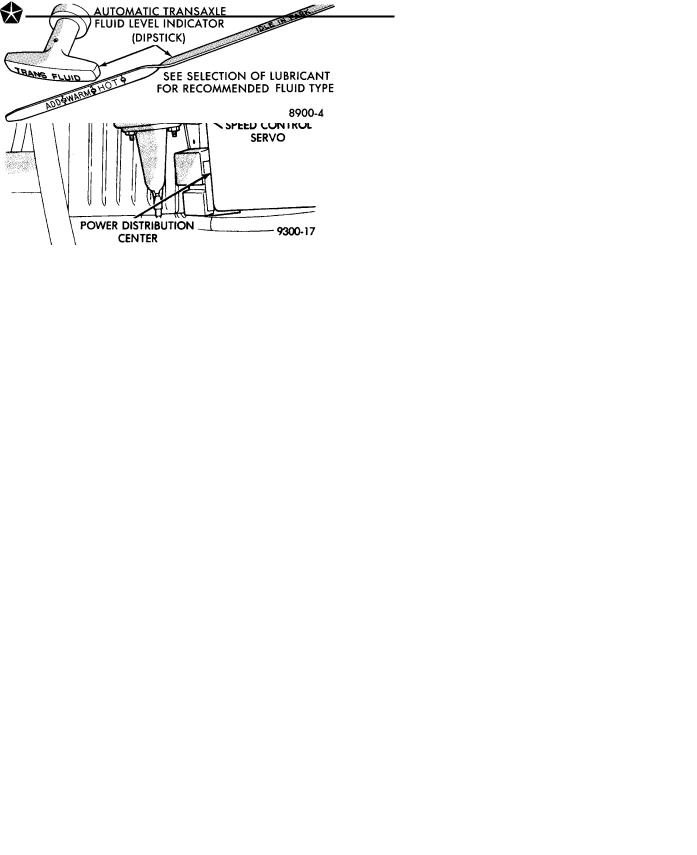
The automatic transaxle should be inspected for fluid leaks and proper fluid level when other under hood service is performed.
CAUTION: To minimize fluid contamination, verify that dipstick is seated in the fill tube after fluid level reading is taken.
TO INSPECT THE TRANSAXLE FLUID LEVEL:
(1)Position the vehicle on a level surface.
(2)Start engine and allow to idle in PARK for at least 60 seconds. The warmer the transaxle fluid, the more accurate the reading.
(3)While sitting in driver seat, apply brakes and place gear selector in each position. Return gear selector to park.
(4)Raise hood and remove transaxle fluid level indicator (dipstick) and wipe clean with a suitable cloth.
(5)Install dipstick and verify it is seated in fill tube (Fig. 1).
CAUTION: Do not overfill automatic transaxle, fluid leak or damage can result.
(6) Remove dipstick, with handle above tip, take fluid level reading (Fig. 2). If the vehicle has been driven for at least 15 minutes before inspecting fluid level, transaxle can be considered hot and reading should be above the WARM mark. If vehicle has run for less than 15 minutes and more than 60 seconds transaxle can be considered warm and reading should be above ADD mark. Add fluid only if level is below ADD mark on dipstick when transaxle is warm.
The automatic transaxle does not require periodic maintenance when used for general transportation. If the vehicle is subjected to severe service conditions, the automatic transaxle will require fluid/filter change and band adjustments every 24 000 km (15,000 miles). For additional information, refer to Severe Service paragraph and Lubrication and Maintenance Schedules in General Information section of this group. The fluid and filter should be changed when water contamination is suspected. If fluid has
|
page |
Tires . . . . . . . . . . . . . . . . . . . . . . . . . . . . . . . . . |
. 14 |
Wheel Bearings . . . . . . . . . . . . . . . . . . . . . . . . . |
. 14 |
foamy or milky appearance, it is probably contaminated. If the fluid appears brown or dark and a foul odor is apparent, the fluid is burned, transaxle requires maintenance or service. A circular magnet located in the transaxle pan, collects metallic particles circulating in the oil. For proper diagnostic and service procedures, refer to Group 21, Automatic Transaxle.
SELECTING AUTOMATIC TRANSAXLE FLUID
Chrysler Corporation recommends Mopar ATF Plus (automatic transmission fluid type 7176) be used to a1dd to or replace automatic transaxle fluid. If ATF Plus is not available use Dexront II or Dexron IIe Automatic Transmission Fluid or equivalent.
Fig. 1 Transaxle Fill tube
Fig. 2 Transaxle DipstickÐTypical
DIFFERENTIAL
The differential should be inspected for oil leaks and proper oil level when other under vehicle service is performed. To inspect the differential oil level, po-
0 - 14 LUBRICATION AND MAINTENANCE
sition the vehicle on a level surface and remove fill plug (Fig. 3). The oil level should be at the bottom edge of oil fill opening.
The differential does not require periodic maintenance when subjected to normal driving conditions. The oil should be changed when water contamination is suspected. If oil has foamy or milky appearance it probably is contaminated. For proper diagnostic and service procedures, refer to Group 21, Transaxle.
SELECTING LUBRICANT
Chrysler Corporation recommends Mopar Gear Lube, SAE 80W-90, or equivalent, be used to fill the differential.
WHEEL BEARINGS
The wheel bearings are permanently sealed, requiring no lubrication. For proper diagnostic and service procedures refer to Group 2, Suspension.
TIRES
The tires should be inspected at every engine oil change for proper inflation and condition. The tires should be rotated at the distance intervals described in the Lubrication and Maintenance Schedules of the General Information section in this group. For tire inflation specifications refer to the Owner's Manual. A Tire Inflation sticker is located in the driver door opening. For proper diagnostic procedures, see Group 22, Wheels and Tires.
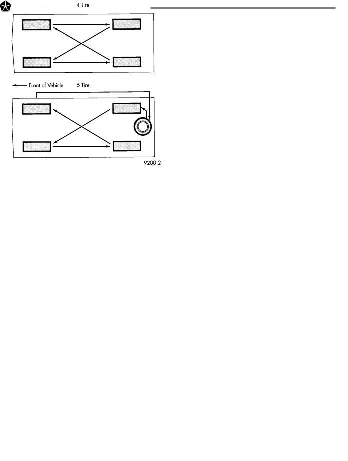
TIRE ROTATION
The Forward Cross rotation method is recommended for use on Chrysler Corporation vehicles (Fig. 5). Other rotation methods can be used, but may not have the benefits of the recommended method. Only the four tire rotation method can be used if the vehicle is equipped with a space saver spare tire.
Fig. 3 Differential Fill Plug
DRIVE SHAFT BOOTS
The front drive shaft constant velocity and tripod joint boots (Fig. 4) should be inspected when other under vehicle service is performed. Inspect boots for cracking, tears, leaks or other defects. If service repair is required, refer to Group 2, Suspension.
Fig. 5 Tire Rotation
Fig. 4 Drive Shaft Boots
|
|
|
|
LUBRICATION AND MAINTENANCE |
0 - 15 |
|
|
|
|
||
|
|
CHASSIS AND BODY |
|
||
|
|
INDEX |
|
||
|
|
page |
|
|
page |
Body Lubrication . . . . . . . . . . . . . . . . . . |
. . . . . . . 16 |
Steering Linkage . . . . . . . . . . . . . . . . . . . . . . |
. . . 15 |
||
Brakes . . . . . . . . . . . . . . . . . . . . . . . . . |
. . . . . . . 15 |
Supplemental Airbag System . . . . . . . . . . . . . |
. . . 16 |
||
Headlamps . . . . . . . . . . . . . . . . . . . . . . |
. . . . . . . 16 |
Suspension Ball Joints . . . . . . . . . . . . . . . . . |
. . . 15 |
||
Power Steering . . . . . . . . . . . . . . . . . . . |
. . . . . . . 15 |
|
|
|
|
STEERING LINKAGE
INSPECTION
The steering linkage and steering gear should be inspected for wear, leaks or damage when other under vehicle service is performed. The rack and pinion steering gear end boots should not have excess oil or grease residue on the outside surfaces or surrounding areas. If boot is leaking, it should be repaired. For proper service procedures refer to Group 19, Steering.
The tie rod end seal should fit securely between the steering knuckle and tie rod end (Fig. 1). The steering linkage should be lubricated at the time and distance intervals described in the Lubrication and Maintenance Schedules. Refer to General Information section of this group.
TIE ROD END LUBRICATION
Lubricate the steering linkage with Mopar Multimileage Lube or equivalent. Using a wiping cloth, clean grease and dirt from around grease fitting and joint seal. Using a grease gun, fill tie rod end until lubricant leaks from around the tie rod end side of the seal (Fig. 1). When lube operation is complete, wipe off excess grease.
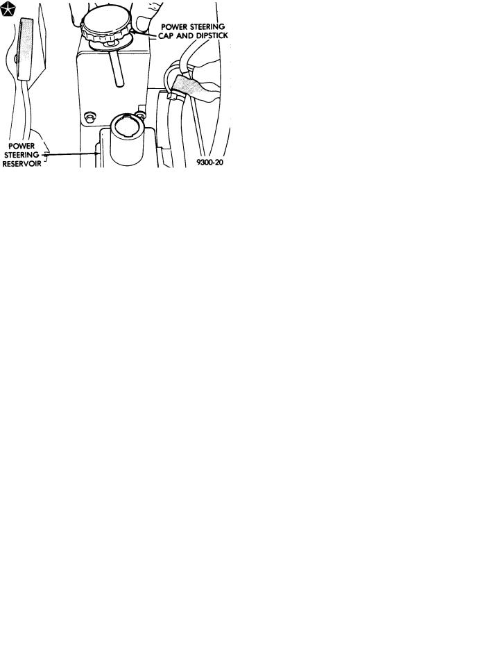
POWER STEERING
The power steering fluid level should be inspected when other under hood service is performed. If the fluid level is low and system is not leaking, use Mopar Power Steering Fluid or equivalent. The power steering system should be inspected for leaks when other under vehicle service is performed. For proper service procedures refer to Group 19, Steering.
The power steering pump drive belt should be inspected at the time and distance interval described in the Lubrication and Maintenance Schedules. Refer to the General Information section of this group.
POWER STEERING FLUID INSPECTION
WARNING: ENGINE MUST NOT BE RUNNING WHEN INSPECTING POWER STEERING FLUID LEVEL, PERSONAL INJURY CAN RESULT.
CAUTION: Do not over fill power steering reservoir when adding fluid, seal damage and leakage can result.
TO INSPECT FLUID LEVEL
(1)Position vehicle on a level surface with engine at normal running temperature.
(2)Turn OFF engine and remove ignition key.
Fig. 1 Tie Rod End Lubrication
SUSPENSION BALL JOINTS
The ball joints are permanently sealed, requiring |
|
|
no lubrication. For proper diagnostic and service pro- |
Fig. 2 Power Steering Reservoir Dipstick |
|
cedures refer to Group 2, Suspension. |
||
|
0 - 16 LUBRICATION AND MAINTENANCE
(3)Using a wiping cloth, clean oil and dirt residue from around power steering reservoir cap.
(4)Remove reservoir cap or dipstick and wipe off
fluid.
(5)Install cap or dipstick.
(6)Remove cap or dipstick. Holding handle or cap above tip of dipstick, read fluid level (Fig. 2). Add fluid if reading is below cold level mark on dipstick.
BRAKES
BRAKE PAD AND LINING INSPECTION
The brake pads and linings should be inspected at distance intervals described in the Lubrication and Maintenance Schedules. Refer to the General Information section of this group. If brake pads or linings appear excessively worn, the brakes would require service. For proper service procedures, refer to Group 5, Brakes.
BRAKE HOSE INSPECTION
WARNING: IF FRONT WHEEL, REAR AXLE, OR AN- TI-LOCK UNIT BRAKE HOSE OUTER COVER IS CRACKED, CHAFED, OR BULGED, REPLACE HOSE IMMEDIATELY. BRAKE FAILURE CAN RESULT.
The front wheel, rear axle and anti-lock unit (if equipped) brake hoses should be inspected at time and distance intervals described in the Lubrication and Maintenance Schedules. Refer to the General Information section of this group. A hose must be replaced if it has signs of cracking, chafing, fatigue or bulging. For proper service procedures, refer to Group 5, Brakes.
BRAKE LINE INSPECTION
The metal brake lines should be inspected when other under vehicle service is preformed. If a line is pinched, kinked, or corroded, it should be repaired. For proper service procedures, refer to Group 5, Brakes.
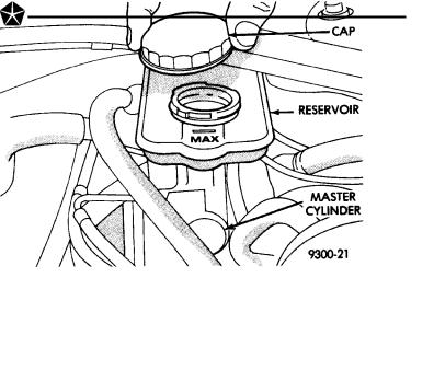
BRAKE RESERVOIR LEVEL INSPECTION
WARNING: DO NOT ALLOW PETROLEUM OR WATER BASE LIQUIDS TO CONTAMINATE BRAKE FLUID, SEAL DAMAGE AND BRAKE FAILURE CAN RESULT.
The brake reservoir level should be inspected when other under hood service is performed. It is normal for the reservoir level to drop as disc brake pads wear. When fluid must be added, use Mopar Brake Fluid or equivalent. Use only brake fluid conforming to DOT 3, Federal, Department of Transportation specification. To avoid brake fluid contamination, use fluid from a properly sealed container.
If fluid level should become low after several thousand kilometers (miles), fill the reservoir to level marks on the side of the reservoir (Fig. 3).
Fig. 3 Brake ReservoirÐTypical
HEADLAMPS
The headlamps should be inspected for intensity and aim whenever a problem is suspected. When luggage compartment is heavily loaded, the headlamp aim should be adjusted to compensate for vehicle height change. For proper service procedures, refer to Group 8L, Lamps.
SUPPLEMENTAL AIRBAG SYSTEM
WARNING: FAILURE TO HAVE THE AIRBAG SYSTEM PROMPTLY SERVICED BY AN AUTHORIZED DEALER SHOULD ONE OF THE FOLLOWING CONDITIONS EXIST CAN LEAD TO POSSIBLE INJURY IN THE EVENT OF AN ACCIDENT.
If the AIRBAG indicator lamp does not light at all, stays lit or lights momentarily or continuously while driving, a malfunction may have occurred. Prompt service is required. Refer to Group 8M, Restraint Systems for proper diagnostic procedures.
BODY LUBRICATION
Body mechanisms and linkages should be inspected, cleaned and lubricated as required to maintain ease of operation and to prevent corrosion and wear.
Before a component is lubricated, oil, grease and dirt should be wiped off. If necessary, use solvent to clean component to be lubricated. After lubrication is complete, wipe off excess grease or oil.
During winter season, external lock cylinders should be lubricated with Mopar Lock Lubricant or equivalent to assure proper operation when exposed to water and ice.
To assure proper hood latching component operation, use engine oil to lubricate the latch, safety
catch and hood hinges when other under hood service is performed. Mopar Multi-purpose Grease or equivalent should be applied sparingly to all pivot and slide contact areas.
USE ENGINE OIL ON
²Door hingesÐPivot points.
²Hood hingesÐPivot points.
LUBRICATION AND MAINTENANCE 0 - 17
² Trunk lid hingesÐPivot points.
USE MOPAR LUBRIPLATE OR EQUIVALENT ON
²Ash receiver slides.
²Door check straps.
²Park brake mechanism.
²Front seat tracks.
²Trunk latch.

SUSPENSION AND DRIVESHAFTS 2 - 1
SUSPENSION AND DRIVESHAFTS
CONTENTS
page
DRIVESHAFTS . . . . . . . . . . . . . . . . . . . . . . . . . 40 FRONT SUSPENSION . . . . . . . . . . . . . . . . . . . . . 4 FRONT SUSPENSION SERVICE PROCEDURES . 6
page
GENERAL INFORMATION . . . . . . . . . . . . . . . . . . 1 REAR SUSPENSION . . . . . . . . . . . . . . . . . . . . . 52 SPECIFICATIONS . . . . . . . . . . . . . . . . . . . . . . . 70
GENERAL INFORMATION
Throughout this group, references may be made to a particular L.H. platform vehicle by letter or number designation. A chart showing the breakdown of these designations is included in the Introduction section at the front of this Service Manual.
The L.H. platform vehicles have a MacPherson gas pressurized strut front suspension design (Fig. 1). The MacPherson strut shock absorber assembly includes the following components. A rubber isolated top mount, seat and bearing assembly and a coil spring insulator. The MacPherson strut assembly is attached to the vehicle at the shock tower using 3 studs which are part of the isolated top mount. The lower end of the MacPherson strut assembly is attached to the upper leg of the steering knuckle. Attachment of the MacPherson strut assembly to the steering knuckle is by 2 serrated bolts. A forged
lower control arm assembly (Fig. 1) is attached to the front cradle and steering knuckle. A tension strut (Fig. 1) connects the lower control arm assembly to the front cradle.
A sealed for life front hub and bearing assembly is attached to the front steering knuckle. The outer C/V joint assembly is splined to the front hub and bearing assembly and is retained by a prevailing torque nut.
CAUTION: ONLY FRAME CONTACT HOISTING EQUIPMENT CAN BE USED ON L.H. PLATFORM VEHICLES. The L.H. platform vehicles have a fully independent rear suspension. The L.H. platform vehicles can not be hoisted using equipment designed to lift a vehicle by the rear axle. If this type of hoisting equipment is used, damage to rear suspension components will occur.

2 - 2 SUSPENSION AND DRIVESHAFTS
Fig. 1 L.H. Platform Front Suspension

SUSPENSION AND DRIVESHAFTS 2 - 3
SUSPENSION/STEERING/DIAGNOSIS FRONT WHEEL DRIVE

2 - 4 SUSPENSION AND DRIVESHAFTS
FRONT SUSPENSION
FRONT SUSPENSION MAJOR COMPONENTS (FIG. 2)
STRUT ASSEMBLY
The front strut and suspension of the vehicle is supported by coil springs positioned around the struts. The springs are contained between an upper seat, located just below the top strut mount assembly (Fig. 2) and a lower spring seat on the strut lower housing.
The top of each strut assembly is bolted to the upper fender reinforcement (shock tower) through a rubber isolated mount.
The bottom of the strut assembly attaches to the top of the steering knuckle with two serrated through bolts and prevailing torque nuts. Caster is a fixed setting (net build) on all vehicles and is not adjustable.
STEERING KNUCKLE
The steering knuckle (Fig. 2) is a single casting with legs machined for attachment to the front strut assembly and lower control arm ball joint. The steering knuckle also has machined abutments on the casting to support and align the front brake caliper assembly. The knuckle also holds the front drive shaft outer C/V joint hub and bearing assembly. The hub is positioned through the bearing and knuckle, with the constant velocity stub shaft splined through the hub. The outer C/V joint is retained to the hub and bearing assembly using a prevailing torque nut.
LOWER CONTROL ARM
The lower control arm (Fig. 2) is a steel forging with 2 rubber bushings isolating the lower control arm from the front cradle assembly. The isolator bushings consist of a metal encased pivot bushing and a solid rubber tension strut bushing. The lower control arm is bolted to the cradle assembly using a pivot bolt through the center of the rubber pivot bushing and at the tension strut isolator bushing (Fig. 2).
The ball joint is an integral part of the control arm and has a non-tapered stud with a notch for clamp
bolt clearance. The stud is clamped and locked into the steering knuckle leg with a clamp bolt. The ball joint used on the L.H. Platform vehicle is non-ser- viceable and if defective must be serviced as part of the lower control arm.
DRIVESHAFTS
A left and right driveshaft is attached inboard to the transaxle differential output (or stub) shaft, and outboard to the driven wheel hub and bearing assembly.
To deliver driving force from the transaxle to the front wheels during turning maneuvers and suspension movement. Both shafts are constructed with constant velocity universal joints at both ends.
Both shafts have a Tripod (sliding) joint at the transaxle end and C/V joints (with splined stub shafts) on the hub ends. Due to the transaxle location the connecting shafts between the C/V joints are of different length and construction. The left shaft is longer than the right. Both the left and right drive shafts are of the solid bar type. No tubular drive shafts are used on any available L.H. platform vehicle and powertrain combinations.
TENSION STRUTS
The L.H. platform vehicle uses a tension strut (Fig. 2) on each side of the vehicles front suspension. The tension strut controls longitudinal (for-and-aft) movement of the front wheels of the vehicles. Controlling the longitudinal movement of the wheels reduces harshness when wheels hit sudden irregularities in the road surface.
STABILIZER BAR (SWAY BAR)
The stabilizer bar (Fig. 2) interconnects the front strut assemblies of the vehicle. The purpose of a stabilizer bar is to control the body roll of the vehicle.
STABILIZER BAR LINK ASSEMBLY
The stabilizer bar link assembly (Fig. 2) is used to attach the stabilizer bar to the front strut assemblies. This reduces the fore-and-aft rate of the sway bar from the rest of the suspension.

SUSPENSION AND DRIVESHAFTS 2 - 5
Fig. 2 L.H. Platform Front Suspension

2 - 6 SUSPENSION AND DRIVESHAFTS
FRONT SUSPENSION SERVICE PROCEDURES
INDEX
|
page |
Ball Joints . . . . . . . . . . . . . . . . . . . . . . . . . . . . . |
. 20 |
Front Suspension Serviceable Components . . . . |
. . 6 |
Front Wheel Alignment . . . . . . . . . . . . . . . . . . . |
. . 6 |
Hub and Bearing Assembly . . . . . . . . . . . . . . . . |
. 34 |
Lower Control Arm Bushing Service . . . . . . . . . |
. 18 |
Lower Control Arm Service . . . . . . . . . . . . . . . . |
. 13 |
Servicing Stabilizer Bar and Bushings . . . . . . . . |
. 21 |
FRONT SUSPENSION SERVICEABLE COMPONENTS
The following components may be replaced either individually or as an assembly.
²Gas pressurized front strut must be replaced as an assembly. The strut is not serviceable. It is not necessary to replace strut assemblies in pairs.
²Strut assembly upper mounts are replaceable.
²Bearing and seat assemblies may be replaced individually.
²Coil springs may be replaced individually from the strut assemblies,
²Coil spring lower isolator may be replaced individually.
²Front wheel hub and bearing assemblies are individually replaceable.
²Front lower control arm assemblies are replaceable. The ball joint is integral to the control arm and will require replacement of the control arm if defective. The ball joint seal is individually replaceable. Lower control arm bushings are serviced as individual components of lower control arm assembly, and do not require replacement of lower control arm if defective.
²Tension struts are replaceable as are the tension strut to cradle assembly isolator bushings. Tension strut washers at the lower control arm and cradle are replaceable, with proper approved replacement parts
ONLY.
²Front stabilizer bar is replaceable. Front stabilizer bar isolator bushings, clamps and stabilizer bar link assemblies are also replaceable.
²Driveshaft seal and boot replacement, is the only service to be performed on the driveshaft assembly. Any failure of an internal driveshaft component will require replacement of the driveshaft assembly.
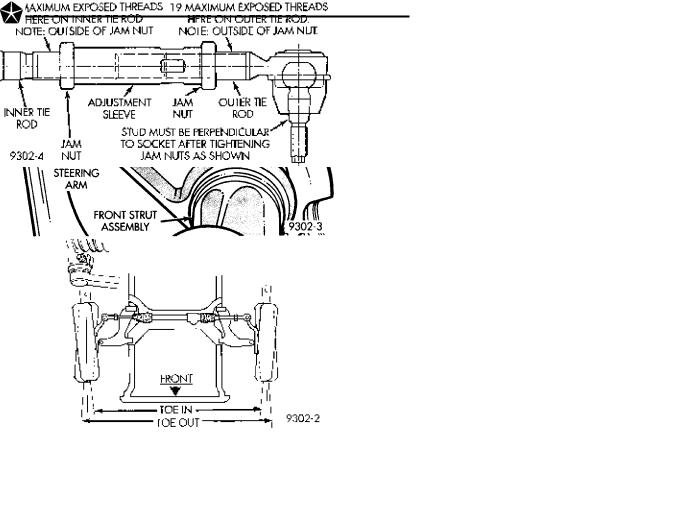
FRONT WHEEL ALIGNMENT
Front wheel alignment is the proper settings of all the interrelated suspension angles affecting the running and steering of the front wheels of the vehicle.
On the L.H. platform vehicle the only adjustable suspension setting is wheel TOE.
The method of checking front alignment will vary depending on the type of equipment being used. The
|
page |
Servicing Wheel Studs . . . . . . . . . . . . . . . . . . . |
. 37 |
Steering Knuckle Service . . . . . . . . . . . . . . . . . . |
. 29 |
Strut Damper Assembly . . . . . . . . . . . . . . . . . . . |
. . 8 |
Suspension Coil Springs . . . . . . . . . . . . . . . . . . |
. 12 |
Tension Strut Service . . . . . . . . . . . . . . . . . . . . |
. 15 |
Wheel Alignment Service Procedure . . . . . . . . . |
. . 7 |
instructions furnished by the manufacturer of the equipment should always be followed. With the exception that the alignment specifications recommended by Chrysler Corporation be used.
There are six basic factors which are the foundation to front wheel alignment. These are vehicle height, caster, camber, toe-in, steering axis inclination and toe-out on turns. Of the six basic factors only TOE
IN is mechanically adjustable on the L.H. platform vehicle (Fig. 1).
CAUTION: Do not attempt to modify any suspension or steering components by heating or bending of the component.
Wheel alignment adjustments can only be made for the Toe In setting on the L.H. platform vehicles.
Toe is measured in degrees or inches and is the distance the front edges of the tires are closer (or farther apart) than the rear edges. See Front Wheel Drive Specifications for Toe settings.
PRE-ALIGNMENT
Before any attempt is made to change or correct front wheel alignment. The following inspection and necessary corrections must be made on those parts which influence the steering of the vehicle.
(1)Check and inflate tires to recommended pressure. All tires should be the same size and in good condition and have approximately the same wear. Note type of tread wear which will aid in diagnosing, see Wheels and Tires, Group 22.
(2)Check front wheel and tire assembly for radial runout.
(3)Inspect lower ball joints and all steering linkage for looseness.
(4)Check for broken or front and rear springs. Alignment must only be checked after the vehicle has
had the following checked or adjusted. Tires set to recommended pressures, full tank of fuel, no passenger or luggage compartment load and is on a level floor or alignment rack.
Just prior to each alignment reading. The vehicle should be bounced (rear first, then front) by grasping
SUSPENSION AND DRIVESHAFTS 2 - 7
bumper at center and jouncing each end an equal number of times. Always release bumpers at bottom of down cycle.
Fig. 1 L.H. Platform Toe Adjustment
WHEEL ALIGNMENT SERVICE PROCEDURE
FRONT WHEEL TOE ADJUSTMENT
(1)Prepare vehicle as described in the PreAlignment procedure.
(2)Center steering wheel and hold with steering wheel clamp.
(3)Loosen tie rod adjustment sleeve jamnuts. Rotate adjustment sleeve to align toe to specifications (Fig. 2).
CAUTION: When setting Toe on the vehicle the maximum threads exposed on the inner and outer tie rod can not exceed the maximum amounts shown in (Fig. 3). If the maximum number of exposed threads is exceeded, inadequate retention of either the inner or outer tie rod may result. Ensure that the adjustment sleeve jam nuts are torqued to the required specifications when the Toe setting procedure is completed.
CAUTION: When torquing the adjustment sleeve jam nuts the following procedure must be followed
Fig. 2 Front Wheel Toe Adjustment
Fig. 3 Tie Rod Adjustment Sleeve Thread Engage-
ment
to ensure adequate torquing and retention of the adjustment sleeve jam nut is obtained.
Install correct size open end wrench on flat of adjustment sleeve to keep adjustment sleeve from turning.
ONE: While holding adjustment sleeve from turning, torque outer tie rod to adjustment sleeve jam nut to 75 NIm (55 ft. lbs.). When outer tie rod jam nut is correctly torqued outer tie rod stud must be perpendicular to socket (Fig. 3).
TWO: While holding adjustment sleeve from turning, torque inner tie rod to adjustment sleeve jam nut to 75 NIm (55 ft. lbs.).
(4)Tighten tie rod adjustment sleeve locknuts to 75 NIm (55 ft.lbs.) torque.
(5)Remove steering wheel clamp.
2 - 8 SUSPENSION AND DRIVESHAFTS
STRUT DAMPER ASSEMBLY
REMOVAL
(1)Raise vehicle on jackstands or centered on a frame contact type hoist. See Hoisting in the Lubrication and Maintenance section of this manual, for the required lifting procedure to be used for this vehicle.
(2)Remove front wheel and tire assembly from the vehicle.
(3)Remove the stabilizer bar attaching link at the strut assembly (Fig. 1).
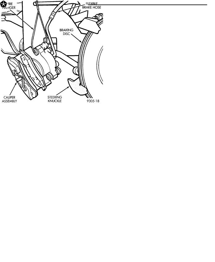
Fig. 3 Speed Sensor Cable Routing Bracket
in this service manual for the required caliper removal and storage procedure. Support caliper assembly by hanging it from frame of vehicle with wire or some other method, do not let caliper assembly hang by brake hose (Fig. 4). Remove front braking disc from hub.
Fig. 1 Tie Rod And Stabilizer Bar Link Removed
(4) Loosen but do not remove the outer tie rod end to strut assembly steering arm attaching nut (Fig. 2). Then remove outer tie rod end from steering arm using Puller, Special Tool MB-990635 or equivalent (Fig. 2).
Fig. 2 Removing Outer Tie Rod From Steering Arm
(5)If vehicle is equipped with Anti-Lock brakes. Remove speed sensor cable routing bracket from front strut assembly (Fig. 3).
(6)Remove brake caliper assembly from steering knuckle and braking disc. Refer to the Brake Section
Fig. 4 Removal And Storage Of Front Caliper
CAUTION: The strut assembly to steering knuckle bolts are serrated were they go through strut assembly and steering knuckle. When removing bolts, turn nuts off bolts DO NOT TURN BOLTS IN STEERING KNUCKLE. If bolts are turned damage to steering knuckle will result.
(7) Remove the strut assembly to steering knuckle attaching bolts (Fig. 5).
 Loading...