

Page 1

Instructions for use
Contents Page
1- GENERAL ................................................................................................................................................................................. 3
1.1 - GENERAL SAFETY RECOMMENDATIONS ............................................................................................................ 3
1.1.1 - STANDARD SAFETY DEVICES ................................................................................................................... 3
1.2 - FIELD OF APPLICATION ......................................................................................................................................... 3
1.3 - OVERALL DIMENSIONS (Standard Protection) ...................................................................................................... 3
1.4 - SPECIFICATION ...................................................................................................................................................... 4
2 - HANDLING AND HOISTING ................................................................................................................................................... 4
3 - COMMISSIONING ................................................................................................................................................................... 5
3.1 - ANCHORING ............................................................................................................................................................ 5
3.2 - ELECTRICAL CONNECTION .................................................................................................................................. 5
3.3 - ADAPTER MOUNTING ............................................................................................................................................ 5
3.4 - GUARD MOUNTING AND ADJUSTMENT ................................................................................................................ 5
3.5 - SPACER WD .............................................................................................................................................................. 5
4 - CONTROLS AND COMPONENTS .......................................................................................................................................... 6
4.1 - BRAKE PEDAL ......................................................................................................................................................... 6
4.2 - DISTANCE AND DIAMETER GAUGE ....................................................................................................................... 6
4.3 - WIDTH GAUGE (Option) ........................................................................................................................................... 6
4.4 - AUTOMATIC WHEEL POSITIONING......................................................................................................................... 6
4.5 - KEYBOARD............................................................................................................................................................... 7
5 - INDICATIONS AND USE OF THE WHEEL BALANCER ........................................................................................................ 8
5.1 - INITIAL SCREEN .................................................................................................................................................... 8
5.1.2 SCREEN-SAVE SCREEN .............................................................................................................................. 8
5.2 - MENU ACCESS DIAGRAM ...................................................................................................................................... 9
5.3 - PRESETTING OF WHEEL DIMENSIONS ............................................................................................................. 10
5.3.1 AUTOMATIC PRESETTING .......................................................................................................................... 10
5.3.2 TO CALL MEMORIZED MEASUREMENTS ................................................................................................. 11
5.3.3 - MANUAL PRESETTING ............................................................................................................................. 12
5.4 - USER CONTROL ................................................................................................................................................... 14
5.4.1 - USER MEMORIZATION ............................................................................................................................. 14
5.4.2 - TO CALL USER .......................................................................................................................................... 14
5.5 - RESULT OF MEASUREMENT ............................................................................................................................... 15
5.5.1 - INDICATION OF EXACT CORRECTION WEIGHT POSITION ................................................................. 16
5.5.2 - “SPLIT” CONTROL ..................................................................................................................................... 17
5.5.3 - UNBALANCE OPTIMIZATION .................................................................................................................... 18
5.5.4 - ALU AND STATIC MODES ......................................................................................................................... 18
5.5.5 - TO CANCEL STATIC UNBALANCE ............................................................................................................ 19
5.6 - ECCENTRICITY MEASUREMENT (OPTIONAL) .................................................................................................. 20
6 - SETUP ................................................................................................................................................................................. 21
6.1 - LANGUAGE ............................................................................................................................................................ 21
6.2 - UNIT OF UNBALANCE MEASUREMENT ............................................................................................................. 21
6.3 - UNBALANCE DISPLAY THRESHOLD ................................................................................................................... 21
6.4 - UNBALANCE DISPLAY PITCH .............................................................................................................................. 21
6.5 - SPIN WITH GUARD CLOSED ............................................................................................................................... 21
6.6 - SCREEN-SAVER TIME .......................................................................................................................................... 21
6.7 - VISUAL ECCENTRICITY CHECK .......................................................................................................................... 21
6.8 - ACUSTIC SIGNAL.................................................................................................................................................... 21
I
CAUTION
7 - SPECIAL CALIBRATIONS AND FUNCTIONS ..................................................................................................................... 22
7.1 - ENABLING OF WIDTH MEASUREMENT (Option)................................................................................................. 22
7.2 - PRESETTING THE CUSTOMER AND USER NAME .............................................................................................. 22
7.3 - ENABLING OF ECCENTRICITY MEASUREMENT................................................................................................ 22
7.4 - CALIBRATIONS........................................................................................................................................................ 22
7.4.1 - GAUGE CALIBRATION ................................................................................................................................ 22
7.4.2 - WHEEL BALANCER CALIBRATION............................................................................................................ 23
7.4.3 - SELF-DIAGNOSTIC WHEEL BALANCING MACHINE ............................................................................... 23
7.4.3.1 - TO CHECK THE ENCODER .................................................................................................................... 23
7.5 - CONTROL OF SERIAL OUTPUT RS232C (OPTION)............................................................................................. 23
8 - ERRORS ................................................................................................................................................................................ 24
9 - ROUTINE MAINTENANCE .................................................................................................................................................... 25
9.1 - SCHEDULED MAINTENANCE ................................................................................................................................ 25
9.2 - TO REPLACE THE FUSES .................................................................................................................................... 25
10 - RECOMMENDED SPARE PARTS LIST .............................................................................................................................. 25
I 0206 - 1
GB
Page 2

I 0206 - 2
GB
Page 3
1234
1384
1655
1- GENERAL
1.1 - GENERAL SAFETY RECOMMENDATIONS
- The balancing machine should only be used by duly authorized and trained personnel.
- The balancing machine should not be used for purposes other than those described in the
instruction manual.
- Under no way should the balancing machine be modied except for those modications made
explicitly by the manufacturer.
- Never remove the safety devices. Any work on the machine should only be carried out by duly
authorized specialist personnel.
- Do not use strong jets of compressed air for cleaning.
- Use alcohol to clean plastic panels or shelves (AVOID LIQUIDS CONTAINING SOLVENTS).
- Before starting the wheel balancing cycle, make sure that the wheel is securely locked on the
adapter.
- The machine operator should not wear clothes with apping edges. Make sure that unauthorized
personnel do not approach the balancing machine during the work cycle.
- Avoid placing counterweights or other objects in the base which could impair the correct
operation of the balancing machine.
1.1.1 - STANDARD SAFETY DEVICES
- STOP push button for stopping the wheel under emergency conditions.
- The safety guard of high impact plastic is with shape and size designed to prevent risk of
counterweights from ying out in any direction except towards the oor.
- A microswitch prevents starting the machine if the guard is not lowered and stops the wheel
whenever the guard is raised.
1.2 - FIELD OF APPLICATION
The machine is designed for balancing car or motorcycle wheels weighing less than 65 kg. It can be
operated within a temperature range of 0° to + 45°C.
It can measure the geometric radial run-out of the wheels (optional)
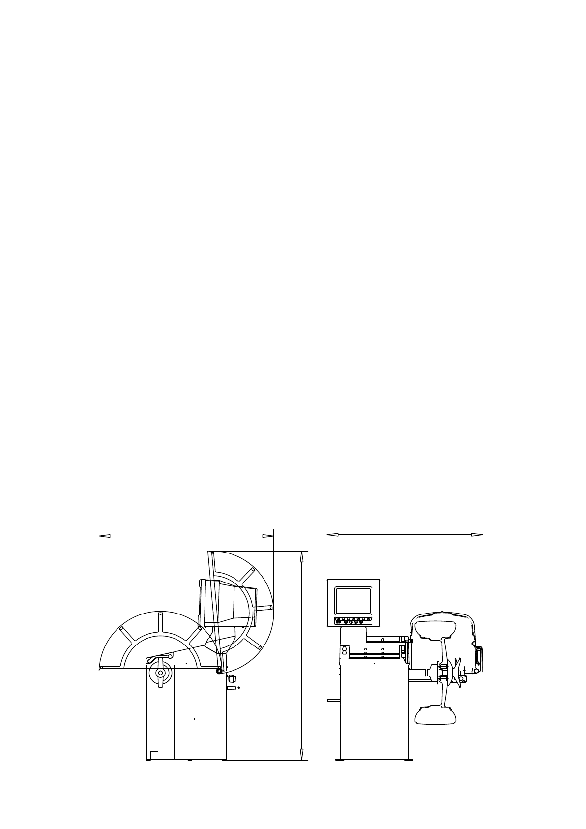
1.3 - OVERALL DIMENSIONS (Standard Protection)
Fig. 1
I 0206 - 3
GB
Page 4
1.4 - SPECIFICATION
Single phase power supply................................ 115 - 230 V 50-60 Hz
Protection class ................................................ IP 54
Max. power consumption................................... 1100 W
Monitor .............................................................. SVGA 15”
Balancing speed approx.................................... 180 min
Cycle time for average wheel (14 Kg) .............6 seconds
Balancing accuracy ...........................................0,5 grammi
Position resolution ............................................. ± 1.4 °
Average noise level ........................................... < 70 dB(A)
Distance rim - machine...................................... 0 - 250 mm (400 mm can be preset)
Larghezza cerchione impostabile ..................... 1.5” ÷ 20” or 40 ÷ 510 mm
Diameter setting range ...................................... 10” ÷ 26” or 265 ÷ 665 mm
Total wheel diameter within guard .....................870 mm (standard) - 1067 (42”)
Total wheel width within guard........................... 430 mm (standard) - 500 (42”)
Max. wheel weight............................................. 65 Kg.
-1
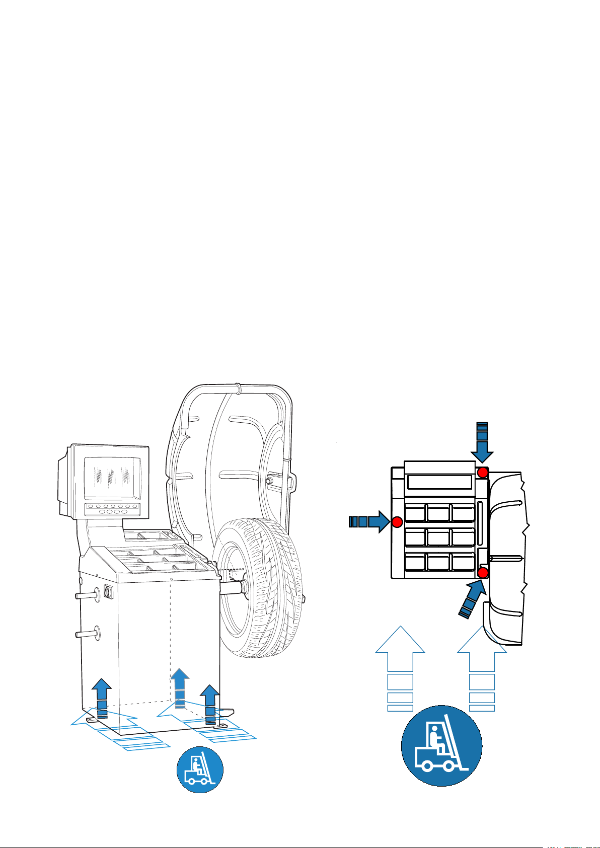
2 - HANDLING AND HOISTING
NB: DO NOT HOIST THE MACHINE USING DIFFERENT GRIPS
Fig. 2 Fig. 2a
I 0206 - 4
GB
Page 5
A
B
Spring
DC
WD
Cone
3 - COMMISSIONING
3.1 - ANCHORING
The machine can be operated on any at non-resilient oor.
Make sure that the machine rests solely on the three support points provided (g. 2a).
It is advisable to secure the system to the ground using the specic feet (see Figure 2a) in the event of
continual use with wheels weighing over 35 Kg.
3.2 - ELECTRICAL CONNECTION
The machine is supplied with a single phase mains cable plus earth (ground).
The supply voltage (and mains frequency) is given on the machine nameplate. It may NOT be changed.
Connection to the mains should always be made by expert personnel.
The machine should not be started up without proper earth (ground) connection.
Connection to the mains should be through a slow acting safety switch rated at 4A (230V) or 10A (115V) .
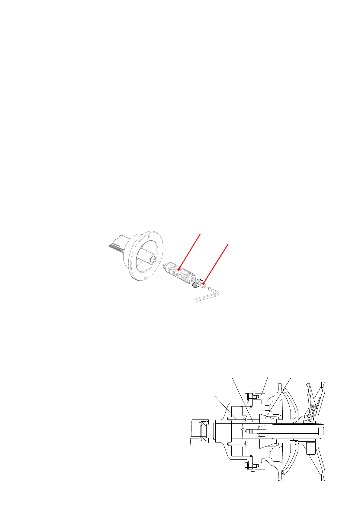
3.3 - ADAPTER MOUNTING
The balancing machine is supplied complete with cone adapter for fastening wheels with central bore.
Other optional adapters can be mounted:
a) Back-off screw B and remove threaded end-piece A.
b) Fit the new adapter.
Fig. 4
3.4 - GUARD MOUNTING AND ADJUSTMENT
a) Fasten the components to the base as illustrated in specic exploded view.
b) The position of the wheel guard when closed can be adjusted with relative screw accessible at the back.
Correct position is the one which keeps the tube exactly horizontal with wheel guard closed.
c) Check that the microswitch is held down when the guard is closed.
d) Adjust the angular position of microswitch control.
3.5 - SPACER WD
When balancing very wide wheels (9”), there is
not enough space to turn the distance gauge.
To withdraw the wheel from the machine side,
t spacer WD on the adapter body and secure
it with the standard issue nuts. When centring
the wheel with the cone on the inside, t the DC
spacer to obtain spring thrust.
I 0206 - 5
GB
Page 6
4 - CONTROLS AND COMPONENTS
4.1 - BRAKE PEDAL
This pedal allows the operator to hold the wheel when tting the counterweights. It must not be actuated
during the measuring cycle.
Fig. 5
4.2 - AUTOMATIC DISTANCE AND DIAMETER GAUGE
This gauge allows measurement of the distance of the wheel from the machine and the wheel diameter at
the point of application of the counterweight.
It also allows correct positioning of the counterweights on the inside by using the specic function (see
INDICATION OF EXACT CORRECTION WEIGHT POSITION) which allows reading, on the monitor, the position used
for the measurement within the rim (For calibration, see GAUGE CALIBRATION).
The gauge can only be used with the counterweight pincers mounted.
4.3 - AUTOMATIC WIDTH GAUGE (OPTIONAL)
Width gauging is through a SONAR device which measures the distance of the wheel without mechanical
contact, merely by closing the guard and each time a valid measurement has been made with gauge
DISTANCE AND DIAMETER GAUGE.
4.4 - AUTOMATIC WHEEL POSITIONING
At the end of the spin, the wheel is positioned according to the unbalance on the outside or else
according to the static unbalance (when selected).
Accuracy is +/-20 degrees.
I 0206 - 6
GB
Page 7
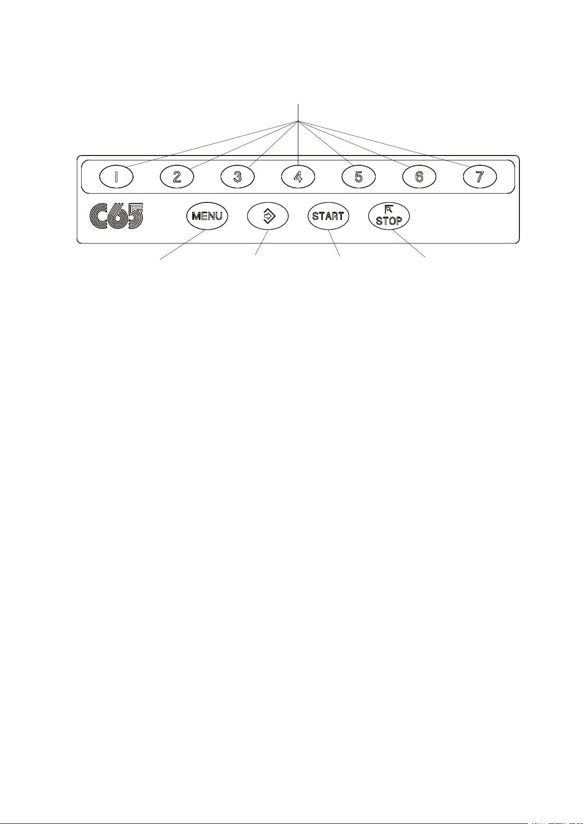
4.5 - KEYBOARD
Fig. 7
N.B. - Press the buttons with the ngers only: never use the counterweight pincers or other
pointed objects.
- When the beep signal is enabled (see section ACUSTIC SIGNAL), pressing of any push button is
accompanied by a “beep”.
FUNCTION KEYS: they immediately select corresponding function
Selection of special
functions
Conrm
Starts measuring
cycle
Stops measuring
cycle
I 0206 - 7
GB
Page 8
5 - INDICATIONS AND USE OF THE WHEEL BALANCER
The monitor shows several information and suggests various alternative ways of use to the operator.
This is through various “screens”.
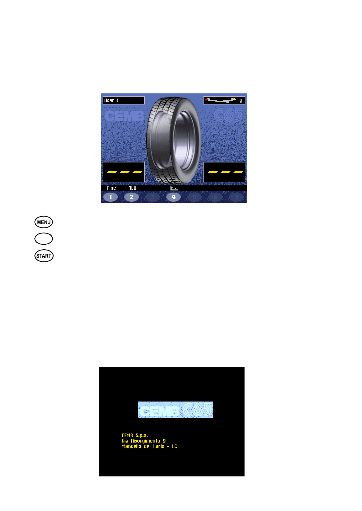
5.1 - INITIAL SCREEN
Buttons enabled
: main functions screen (see MENU ACCESS DIAGRAM)
2
Dimensions gauge: when extracted, the Dimensions screen is selected (see PRESETTING OF WHEEL
DIMENSIONS).
If the machine remains on the initial screen for a certain amount of time without being used, the system
is automatically switched to a screen-save. Striking of any key, movement of the wheel of distance +
diameter gauge will cause automatic switching from the screen-save menu to the initial screen.
: type of correction (see ALU AND STATIC MODES)
: balancing spin (see RESULT OF MEASUREMENT)
5.1.2 SCREEN-SAVE SCREEN
N.B. Name of the wheel balancer’s owner. Can be preset via the monitor
(see Section PRESETTING THE CUSTOMER AND USER NAME)
I 0206 - 8
GB
Page 9

GB
5.2 - MENU ACCESS DIAGRAM
N.B. - The symbol
indicates the presence of a further menu.
- To return to the previous menu, press button
- To return to the initial screen, press button
User control
Machine parameters set-up
H
Language
Unit of unbalance measurement
Unbalance display threshold
Unbalance display pitch
Spin with guard closing
Screen-saver time
Cancel
Machine parameters set-up
Visual eccentricity check
Acustic signal
B
selections
user control
A
C
Call user
Save user
Optimization
Dimensions
Set-up
Special functions
Cancel
PASSWORD : + + +
ONLY FOR SPECIALIST PERSONAL
D
Width measurement
Eccentricity measurement
Customer’s personal data
User’s names
Calibration
5
3
Special functions
7
Previous
Calibrations
Distance
Diameter
Width
Cancel
F
E
Calibrations
Potentiometer
Eccentricity correction
Self-diagnostic wheel balancer
Autodiagnosi
Cancel
Cancel
Cancel
I 0206 - 9
Page 10

b
5.3 - PRESETTING OF WHEEL DIMENSIONS
5.3.1 AUTOMATIC PRESETTING
INDICATOR:
Width Sonar
function enabled
INDICATOR
L.T. function enabled
(see Buttons Enabled)
The screen appears upon removing the distance + diameter gauge.
The indication “dimension acquired” is given by the symbol of the correction weight which changes from
blue to red.
- Standard wheels: Using the appropriate handgrip, move the end of the gauge against the rim in one
of the positions A/B shown in gure 8:
- Hold the gauge still in position for at least 2 seconds.
N.B. - Always use the round part of the gauge striker surface
Fig. 8
POS.A
If the beep signal is enabled (see ACUSTIC SIGNAL),
successful acquisition of the dimensions is accompanied by a “beep”.
- Press
- In manual mode, preset width “b”
(see MANUAL PRESETTING).
- Normally the “nominal” width is stamped on the
rim; or else measure dimension “b” with the calliper
gauge (standard accessory).
6
POS.B
AUTOMATIC WIDTH MEASUREMENT (OPTIONAL)
Gradually lower the guard after carrying out measurement of distance + diameter in automatic mode.
If the width measured is incorrect (out of range), the following message appears:
“Sonar measure is out of range:”
“F1 = repeat”
“F2 = manual set-up”
I 0206 - 10
GB
Page 11
Press F1 to re-lower the guard and repeat the width measurement. Press F2 to go to the dimensions
panel for manual insertion of the width measurement.
The calibration performed as such is necessary for modes AL1,2,3,4,CTS,Static, Dynamic.
Manually presetting is possible by using the push buttons as described in TO CALL MEMORIZED MEASUREMENTS.
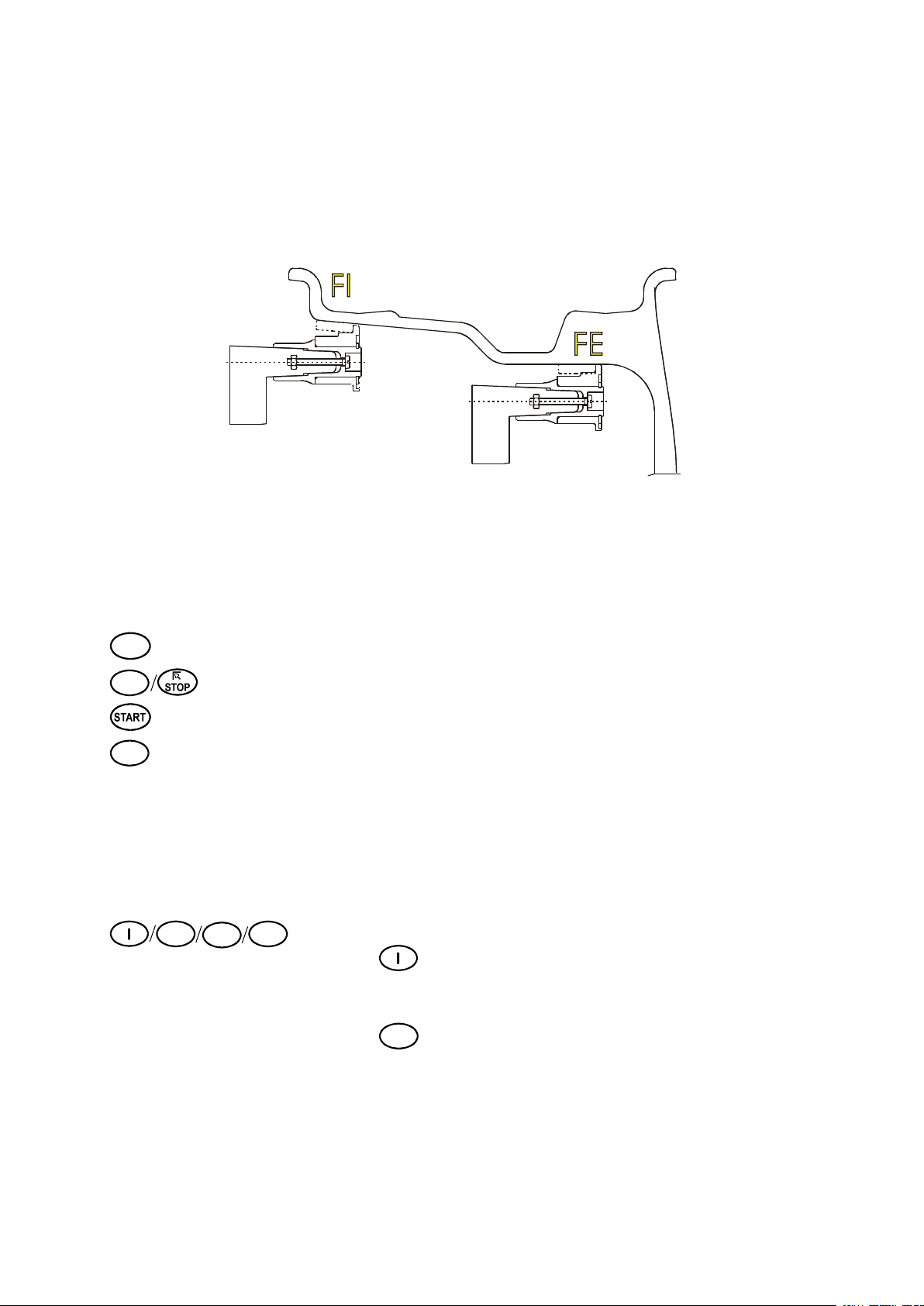
Fig. 9
- Wheel ALU-S (correction from the inside for two balancing planes with direct calibration):
After the measurement carried out for the inside FI as described in g. 9, pull out the gauge further to
memorize the data for the outside FE: keep this position for at least 2 seconds.
The counterweight symbols change colour.
When the acoustic signal is enabled (see ACOUSTIC SIGNAL), the acquisition is accompanied by a “beep”.
The following buttons are enabled:
Select the dimensions presetting in manual mode screen.
6
/ Return to initial screen.
7
Balancing spin
5
AUTOMATIC WIDTH MEASUREMENT OPTION enabled:
The button LT (LIGHT TRUCK) serves for improved dimensional calibration of
large size wheels such as off-the-road vehicles, trucks, or wheels which project
by a large amount from the rim. Press button LT after the distance measurement
and immediately upon lowering the wheel guard for width measurement. The
optional feature is automatically disabled upon measuring another wheel.
5.3.2 TO CALL MEMORIZED MEASUREMENTS
2
4
3
Press the button with relative user’s name:
- when
is pressed, the stored measurements will be called
(USER MEMORIZATION) while disregarding other measurements made in
the meantime.
- when
2
is pressed, the currently preset dimensions are saved.
I 0206 - 11
GB
Page 12

b
a
d
5.3.3 - MANUAL PRESETTING
If necessary, the dimensions can be inserted or edited in manual mode as follows:
- press
reached by pulling out the distance + diameter gauge).
- press
- press
- press
- press
Denition of dimensions:
d = DIAMETER: Preset the nominal diameter stamped on the rim.
b = WIDTH: Preset the nominal width indicated on the rim.
a = DISTANCE: Preset the distance of the inside of the wheel from the machine, after measuring
it with relative gauge as described in g. 8.
2
5
6
4
+
to select the dimension to be preset .
/
to change unit of measurement.
to preset the dimensions for the ALU-S correction mode
or else press
3
to preset the required value.
Fig. 10
6
from the Dimensions in automatic mode screen (which can be
I 0206 - 12
GB
Reading
Lettura
Page 13

14 mm
- ALU S wheel
Likewise in the ALUS correction mode, the dimensions can be entered or changed manually by using the
buttons indicated on the screen and by following the diagram indicated by the graph.
To access the Manual ALUS dimensions presetting screen, press:
1) CUTTING SETTING TYPE OF CORRECTION = ALUS
+ or from the dimensions screen in automatic mode (can be reached by pulling out
the distance + diameter gauge)
2) CURRENT SETTING TYPE OF CORRECTION ≠ ALUS
+ +
For a clearer understanding of the indications given by the graph, consult the following diagram:
distance reading
- To return to the standard wheel dimensions presetting screen, press button
I 0206 - 13
GB
Page 14

5.4 - USER CONTROL
The wheel balancer can be used simultaneously by 4 different users who, through a simple sequence,
can memorize their work condition and call it when needed. The users’ names can be memorized
(CALIBRATIONS).
5.4.1 - USER MEMORIZATION
- Preset the dimensions correctly according to the procedures already described in sections AUTOMATIC
PRESETTING and TO CALL MEMORIZED MEASUREMENTS.
- Press
; the “MENU” window appears on the monitor.
- Press
- Press the number corresponding to the required USER. The system returns to the initial screen
automatically.
2
; a window appears with the list of available USERS. The current user is displayed in red.
5.4.2 - TO CALL USER
- Perform a measuring spin with any dimensions.
- Press button
- Press
- Press the number corresponding to the required USER. The system automatically returns to the initial
screen with recalculation of the unbalance values on the basis of the effective dimensions of the USER
called.
- Alternatively, proceed as described in section TO CALL MEMORIZED MEASUREMENTS.
N.B. - The dimensions memorized as USER are lost when the machine is switched off.
- The USER control is also valid for the ALU-S dimensions.
- The current USER is always displayed in the Measurements and Dimensions screens.
.
: a window appears with the list of available USERS. The current user is displayed in red.
; the “MENU” window appears on the screen.
I 0206 - 14
GB
Page 15
GB
5.5 - RESULT OF MEASUREMENT
After performing a balancing spin, the unbalance values are displayed as well as arrows useful for
positioning the point of application of the correction weight. After positioning the wheel, apply the weight in
the 12 o’clock position.
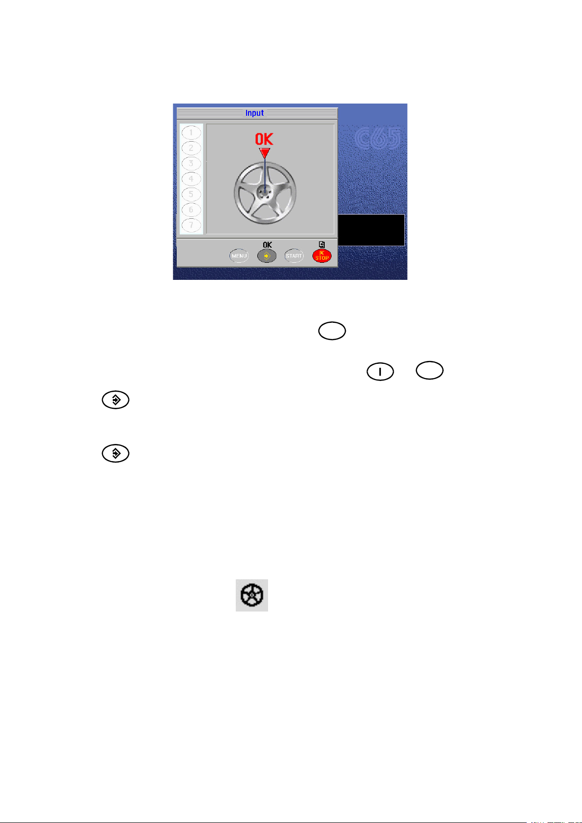
If the unbalance is less than the chosen threshold value, the “OK” appears instead of the unbalance value
to indicate, on that particular side, the wheel is in tolerance; the residual unbalance can be displayed by
pressing button
with an accuracy of 0.5 g (0.1 oz).
The following buttons are enabled:
Display of residual unbalance
2
4
6
7
N.B. If the machine remains on this screen without being used for more than the time preset in the
Setup parameters (6), the screen automatically returns to the screen-save.
Selection of correction mode (DYNAMIC, STATIC, ALU1, ALU2, ALU3, ALU4, CTS).
When the mode is changed, the unbalance values are recalculated automatically on the
basis of the previous spin (ALU AND STATIC MODES).
Eccentricity measurement graph (optional). The symbol appearing above the button
changes to red if the eccentricity is excessive.
Split control for splitting of unbalance over presettable components (“SPLIT” CONTROL).
Button only enabled in STATIC or ALU S correction.
Indication of the longitudinal position of the unbalance (INDICATION OF EXACT CORRECTION
WEIGHT POSITION) is enabled
For selection of special functions
Balancing spin.
I 0206 - 15
Page 16

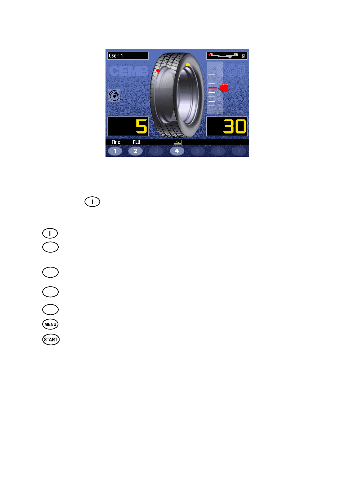
5.5.1 - INDICATION OF EXACT CORRECTION WEIGHT POSITION
It is recommended to always use this function when correcting the unbalance through adhesive weights:
ALU S, STATIC.
In all cases this function allows cancelling approximations in the mounting of counterweights with
consequent reduction of the residual unbalance.
7
- Press button
- Pull out the rim distance + diameter gauge in position A, gure 8. Approach of the weight to the
correction position is indicated by a moving coloured arrow [ ].
- When a xed arrow [ ] is reached, rotate the wheel to correction position (FI or FE) and apply the
counterweight by turning the tip of the gauge towards the outside, into the position in which the pincers touches
the wheel. Compensation is made for the fact that the weight application position is no longer at 12 o’clock (g. 11).
When the acoustic signal is enabled (see ACOUSTIC SIGNAL), the reaching of a xed arrow [ ] is
accompanied by a “beep”.
from the Measurements screen.
Fig. 11
I 0206 - 16
GB
Page 17
5.5.2 - “SPLIT” CONTROL
The SPLIT function is only possible in the case of static unbalance or ALU-S on the outside. It serves for
concealing any stick-on unbalance correction weights behind the rim spokes.
TO PRESET THE NUMBER OF RIM SPOKES
- From the STATIC or ALU-S measurement screen, press
6
;
- A window appears on the display indicating the currently preset number of spokes.
- Set the required number of spokes in the range 3 to 12 by pressing
- press
- Bring a spoke to the 12 o’clock position.
- press
The ALU-S unbalance on the inside does not vary while as regards the STATIC unbalance and that
ALU-S on the outside:
- Gradually turn the wheel until an unbalance value appears.
- Apply an adhesive weight of the value indicated on the screen for the outside or STATIC, behind
the spoke in the 12 o’clock position.
- Again turn the wheel until a new unbalance value appears.
- Apply an adhesive weight of the value indicated on the screen for the outside or STATIC, behind
the spoke in the 12 o’clock position.
- Perform a spin to check for correct wheel balancing.
N.B. When SPLIT is enabled, the icon appears to the left of the screen.
to conrm the presetting.
; the Measurement Screen reappears with the unbalance values already split.
and
2
I 0206 - 17
GB
Page 18
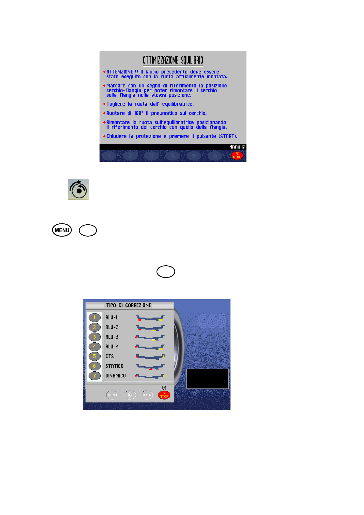
5.5.3 - UNBALANCE OPTIMIZATION
The symbol is displayed automatically for static unbalance exceeding 30 grams (1.1 oz). The
program allows reducing the total unbalance of the wheel by compensating, when possible, the unbalance
of the tyre with that of the rim. It requires two spins with rotation of the tyre on the rim in the second spin.
Press
+
3
after a rst spin and follow the instructions appearing on the monitor.
5.5.4 - ALU AND STATIC MODES
From the Measurement screen, press button
2
: a window with the possible modes appears.
Select the type required through the numeric keys. The return to the Measurement screen with the
recalculated values is automatic. A symbol always appears at the top of the screen indicating the enabled
weight application position.
I 0206 - 18
GB
Page 19

STANDARD Balancing of steel or light alloy rims with application of
clip-on weights on the rim edges
STATIC The STATIC mode is necessary for motorcycle wheels or
when it is not possible to place the counterweights on
both sides of the rim.
ALU - 1 Balancing of light alloy rims with application of adhesive
weights on the rim shoulders.
ALU - 2 Balancing of alloy rims with hidden application of the
adhesive weight on the outside. The position of the out
side weight is on the adapter surface.
12/13 mm
Resting surface
ALU - 3 Combined application: clip-on weight inside and hidden a
dhesive weight on the outside (Mercedes). Outside
weight position is the same as ALU-2.
ALU - 4 Combined application: clip-on weight the outside and
hidden adhesive weight inside
CTS Special balancing with snap-in adhesive weights between
the edge of the tyre and rim, for both sides.
5.5.5 - TO CANCEL STATIC UNBALANCE
This function can be selected from the Setup screen. It serves for optimizing the residual unbalance by
correcting a wheel with standard counterweights in steps of 5 grams (1/4 oz.).
Thanks to this particular function, the position and best correction value are calculated in order to cancel
the static unbalance: the main cause of the vibrations which can be felt inside the car.
I 0206 - 19
GB
Page 20
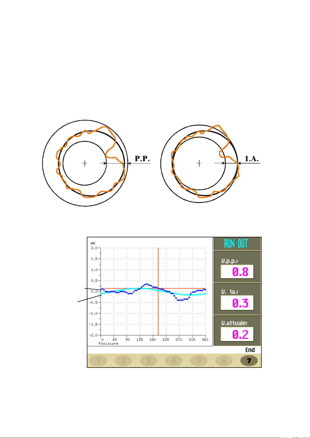
5.6 - ECCENTRICITY MEASUREMENT (OPTIONAL)
The much enlarged gures show the outer tyre surface and axis of wheel rotation.
Fig. A shows measurement of the total Peak-to-Peak eccentricity dened as maximum radial deviation
of the tyre surface.
Fig. B shows measurement of the eccentricity of the 1st harmonic, i.e. the eccentricity of that circle which
“recopies” the tyre shape, by averaging the local deviations of the tyre from the round shape.
Obviously the P.P. measurement is normally greater than that of the 1st harmonic. Tyre manufacturers
normally supply two different tolerances for the two eccentricities.
At the end of the balancing spin it is possible to automatically measure the eccentricity of the tyre
through the SONAR sensor installed on the guard. The sensor should be positioned by hand in front
of the tyre tread.
GRAPH 1 - (yellow)
GRAPH 2 - (red)
GRAPH 1 : represents the actual Peak-to-Peak eccentricity.
GRAPH 2 : represents the eccentricity of the 1st harmonic. For a wheel in optimum conditions, such graph
should approach a straight line.
When the wheel is moved, the cursor on the screen indicates the actual value, with the phase referred
to the eccentricity measurement sensor.
I 0206 - 20
GB
Page 21

6 - SETUP
(see Diagram showing access to the menus)
The Setup screen provides the user with many possibilities required for presetting the machine according
to his own requirements. Such settings remain unaltered even when the machine is switched off.
The following buttons are enabled:
: return to previous window
: return to Measurement screen
from to : for selection of the parameter.
7
6.1 - LANGUAGE
This function allows selecting the language to be used for displaying descriptive and diagnostic messages
regarding machine operation.
6.2 - UNIT OF UNBALANCE MEASUREMENT
It is possible to select whether to display the unbalance values expressed in grams or ounces .
6.3 - UNBALANCE DISPLAY THRESHOLD
This consists of the unbalance threshold below which the wording “-OK-” appears on the screen at the end
of the spin instead of the unbalance; the presettable values vary according to the unit of measurement
selected.
6.4 - UNBALANCE DISPLAY PITCH
This represents the display pitch of the unbalance and varies according to the unit of measurement
selected. The selection “5 g” (1/4 oz) enables display of the correction values on both sides such as to
bring the static unbalance to 0 (theoretical). It is recommended to preset this function as standard use
of the machine as it improves the balancing quality. The computer makes a complex calculation which
allows cancelling the residual static unbalance by varying the value and position of the counterweights
xed in steps of 5 grams (1/4 oz).
6.5 - SPIN WITH GUARD CLOSED
When “ON” is selected the automatic start of the spin is enabled when the guard is closed.
6.6 - SCREEN-SAVER TIME
When the machine remains unused for longer than the time preset with this function, the processor
automatically returns to the Initial screen. Preset the time in seconds.
6.7 - VISUAL ECCENTRICITY CHECK
At the end of wheel acceleration, as soon as the motor is disengaged, the guard can be opened for visual
control of any wheel eccentricity as the rotation speed gradually drops.
Do not strike the wheel during the entire deceleration stage; to brake the wheel, close the guard. However,
avoid using the brake as far as possible because this may compromise unbalance measurements. The
unbalance values measured are only displayed when the wheel has come to a standstill.
This function is active for only one machine run.
6.8 - ACOUSTIC SIGNAL
When “ON” is selected. the sending of an acoustic signal (beep)) is enabled in the following cases:
- when any push button is pressed;
- when dimensions are acquired in automatic mode;
- when the correct angular position for weight application is reached in the Measurement screen;
- when the correct angular position for weight application is reached in the Position Repeater screen.
I 0206 - 21
GB
Page 22

- CAUTION -
7 - SPECIAL CALIBRATIONS AND FUNCTIONS
(See Access diagram)
In order to gain access to the “Reserved Calibrations and functions” it is necessary to enter a password.
Any incorrect operation within the functions described below could impair the operation of the wheel
balancing machine. Unauthorized use will cause cancellation of the warranty on the machine.
7.1 ENABLING OF WIDTH MEASUREMENT (OPTIONAL)
This function enables/disables automatic width measurement with SONAR or contact device: select “OFF”
under normal conditions and “SONAR” if the machine has provision for automatic width measurement.
7.2 - PRESETTING THE CUSTOMER AND USER NAME
The machine can be customized by presetting:
a) The name appearing on the Initial screen (screen-save).
b) The name of 4 different machine users ( USER NAME).
An “ideal” keyboard appears on the monitor with the set of characters available for composition of the
wordings.
The Customer’s name consists of three lines, each max. 30 characters.
The USER NAME consists of a wording max. 15 characters.
7.3 - ENABLING OF ECCENTRICITY MEASUREMENT (OPTION)
Enables/disables measurement of the tyre eccentricity during an unbalance measurement spin.
7.4 - CALIBRATIONS
When
7.4.1- GAUGE CALIBRATION
Select the gauge to be calibrated and follow the instructions appearing on the monitor.
N.B.:
- In the diameter gauge calibration it is highly important to position the gauge correctly as shown in gure 8.
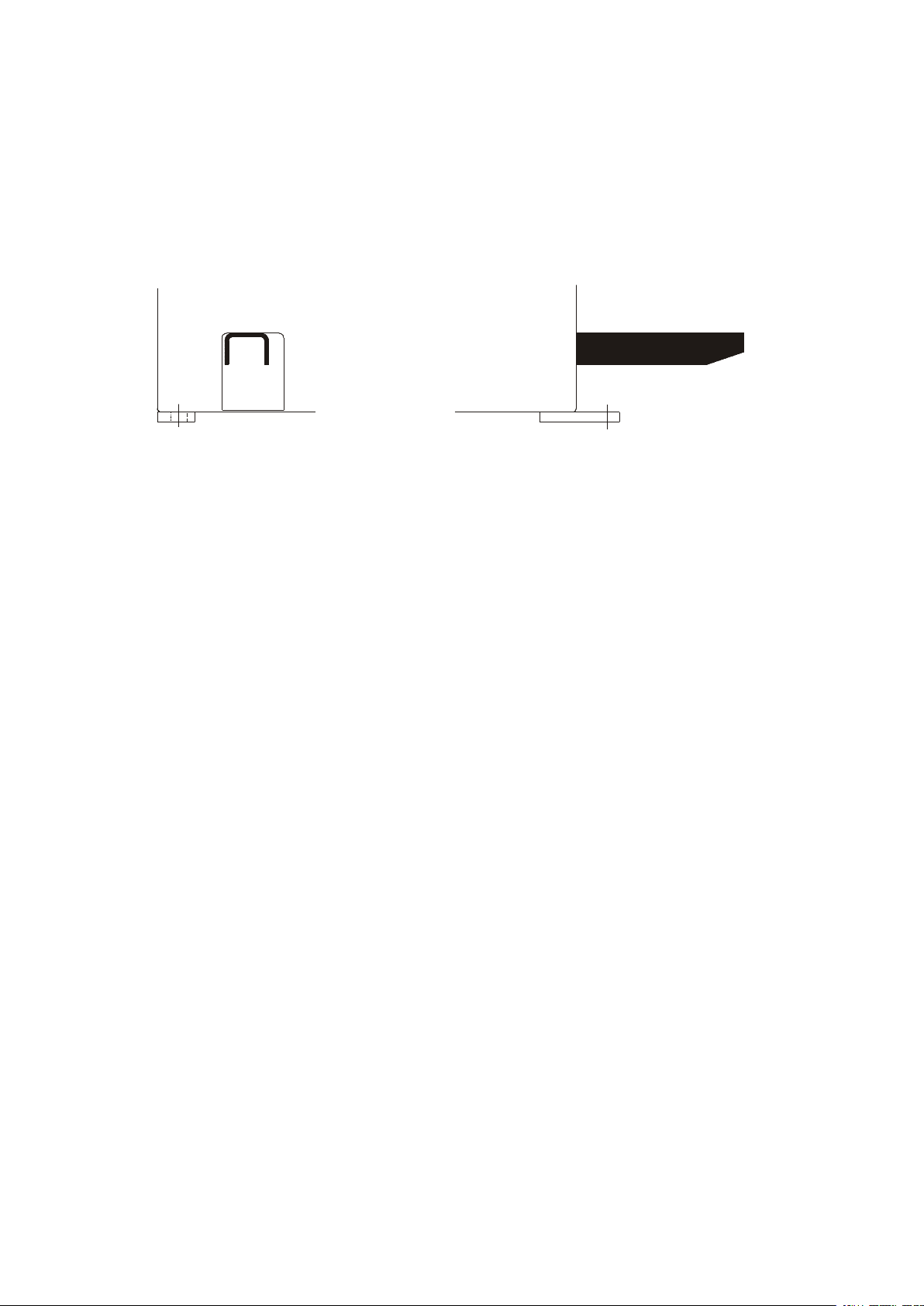
- In the width gauge calibration it is necessary to enter two dimensions which can be measured as follows:
A - GAUGE “ZERO” DISTANCE
SONAR “ZERO” DISTANCE
Fig. 12
6
is pressed from the Special Functions menu, access is gained to the Calibration menu.
B - DISTANCE FROM CALIBRATION POINT
Fig. 13
I 0206 - 22
GB
Page 23

7.4.2 - WHEEL BALANCER CALIBRATION
For calibration of the machine, proceed as follows:
- Use a medium-sized metal wheel. Example: 6” x 14” (± 1”)
- Preset the wheel dimensions with GREAT CARE.
- Follow the instructions appearing on the monitor.
7.4.3 - SELF-DIAGNOSTIC WHEEL BALANCING MACHINE
An automatic self-diagnostics cycle is provided for easier trouble shooting. At the end of the selfdiagnostics cycle, several parameters are displayed which are useful for the Technical Service Department in order to identify machine faults.
Returns to previous menu.
7.4.3.1 - TO CHECK THE ENCODER
When the spindle is rotated:
- the angular position “POS” should vary from 0 to 128;
- the wording “UP” should appear when rotated clockwise and “DOWN” when rotated in the opposite
direction.
Encoder check
Check for correct
operation of the
distance gauge;
the number increases when the gauge
is pulled out.
Check of the eccentricity sonar (option): the number
decreases when a surface is approached to the
sonar.
In the event of failure or faulty operation of the wheel balancing machine, notify the Technical Service
of all the parameters displayed.
Check for correct operation of the diameter
gauge; the number
increases when the
gauge is rotated
outwards
Check of the width
sonar (option): the
number decreases
when a surface is
approached to the
sonar.
7.5 CONTROL OF SERIAL OUTPUT RS232C (OPTION)
This option enables/disables the sending of the measured unbalance and phase values to serial output
RS232C.
Transmission speed = 9600 baud
Data format = 7 bit Start
7 bit Data
1 bit Even parity
1 bit Stop
At the end of each unbalancing measuring spin, the balancing machine enables the RTS signal, then
places the “$” character on standby to be able to transmit the data; all functions remain on hold until data
transmission is enabled, at the end of which the RTS signal is reset to the inactive state.
The items of data transmitted via serial line are in ASCII format and are separated between each other
by the <cr> character (0x0d).
Sending sequence is as follows:
- 0000 <cr>
- Value of correction weight, left side <cr>
- Correction phase, left side <cr>
- Value of correction weight, right side <cr>
- Correction phase, right side <cr>
The rst 5 zero bytes represents the start of transmission message. The correction values are expressed
in grams, in steps of .1 gram. The phase values are expressed in degrees, in the range 0% 359.
I 0206 - 23
GB
Page 24

8 - ERRORS
ERROR MEANING
1 No rotation signal. Could be due to a faulty position transducer, or to the
motor failing to start, or to something preventing the wheel from turning.
2 During the measurement spins, wheel speed had dropped below 60
r.p.m. Check encoder functioning (see TO CHECK THE ENCODER) and
repeat the spin.
3 Error in the mathematical calculations, most probably caused by incorrect
carrying out of the self-calibration. Repeat the self-calibration. Wheel
unbalance too high.
4 Motor turning in opposite direction.
5 Guard open before start of spin.
7/8/9 Fault in the machine setup parameters.
Check for correctness of the basic setup parameters and repeat the
machine calibration. Contact Technical Service.
11 Speed too high for the measurement.
12/13/14 Overow of counters used for the measurement. Check encoder functio
ning (see TO CHECK THE ENCODER). Contact Technical Service.
15/16/17/18 Contact Technical Service.
20 Wheel stopped before having positioned it.
40 ÷ 53 Error in control of eccentricity measurement graphs
I 0206 - 24
GB
Page 25

9 - ROUTINE MAINTENANCE
9.1 - SCHEDULED MAINTENANCE
Switch off the machine from the mains before carrying out any operation.
Grease lubricate the movable blade of the weight dispenser
9.2 - TO REPLACE THE FUSES
Remove the weight holder shelf to gain access to the power supply board where some fuses are
located (see Exploded Views). If fuses require replacement, use ones of the same
current rating. If the fault persists, contact Technical Service.
NONE OF THE OTHER MACHINE PARTS REQUIRE MAINTENANCE
10 - RECOMMENDED SPARE PARTS LIST
(For further details, see exploded drawings)
CODE DESCRIPTION
020600503 Bearing 6005-2Z dia. 25/47/12
181198630 Spring 19863P
080077007 Rigid belt Poly V - TB2 - 770 - 7 Vee’s
67M38954H Position pick-up board with cable
182245870 Spring, brake lever 24587P
05PR39772 LEXAN panel
182185750 Spring, rim distance gauge
67M48208A Power board
681002000 Fuses DM 5x20 - 2A
511231002 Switch KL 1002 + Q555
86SC52431 Computer board
86SB36752 Cable, automatic rim distance gauge
86SB36751 Cable, automatic diameter gauge
801100164 15” colour monitor SVGA
86SB35179 Width sonar
86SB34144 Cable with microswitch for standard protection
86SB35585 Cable with microswitch for 42” protection
SPECIAL PARTS FOR 230V MACHINES
501054213 Single phase motor BIMA 230V/50-60 Hz -0.18Kw 63/B3 - 4p.
86SZ52116 Complete power board
611000314 Braking transformer 30VA 230 - 0/50
568001458 Capacitor 14MF 450 V FASTON screw M8
611035188 Power transformer 40VA
SPECIAL PARTS FOR 115V MACHINES
502054114 Single phase motor BIMA 115V/50-60Hz- 0.18Kw - 63/ B3 - 4p
86SZ52117 Complete power board
611000313 Braking transformer 30VA 115-0/25
568002557 Capacitor 25MF 450V FASTON screw M8
611035187 Power transformer 40VA
I 0206 - 25
GB
 Loading...