

Page 1

Instructions for use
INDEX page
1 - GENERAL ..................................................................................................................................................................... 3
1.1 - GENERAL SAFETY REGULATIONS ..............................................................................................................3
1.1.1 - STANDARD SAFETY DEVICES .........................................................................................................3
1.2 - FIELD OF APPLICATION ...............................................................................................................................3
1.3 - OVERALL DIMENSIONS ...............................................................................................................................3
1.4- TECHNICAL DATA ............................................................................................................................................4
2 - TRANSPORT, HOISTING ...........................................................................................................................................4
3 - START-UP ...................................................................................................................................................................5
3.1 - ANCHORING ....................................................................................................................................................5
3.2 - ELECTRICAL CONNECTION ........................................................................................................................5
3.3 - ADAPTER MOUNTING ..................................................................................................................................5
3.4 - FITTING AND ADJUSTING THE GUARD ....................................................................................................... 5
3.5 - SPACER WD ......................................................................................................................................................5
4 - CONTROLS AND COMPONENTS .............................................................................................................................6
4.1 - MANUAL DISTANCE MEASUREMENT GAUGE ( C 61 ) ................................................................................6
4.2 - AUTOMATIC DISTANCE AND DIAMETER GAUGE ( C 61 Z ) ..........................................................................6
4.3 - AUTOMATIC WHEEL POSITIONING ...............................................................................................................6
4.4 - CONTROL PANEL AND DISPLAY ..................................................................................................................6
4.4.1 OPERATION FUNCTIONS MENU ...........................................................................................................7
5 - INDICATION AND USE OF THE WHEEL BALANCER .............................................................................................8
5.1 - DOUBLE OPERATOR PROGRAM ................................................................................................................8
5.2 - PRESETTING OF WHEEL DIMENSIONS .....................................................................................................8
5.2.1 - AUTOMATIC PRESETTING ( C 61 Z ) ...............................................................................................8
5.2.2 - MANUAL PRESETTING ( C 61 ) ......................................................................................................9
5.2.3 - SETTING WITH GAUGE EXTENSION ( OPTIONAL C 61 ) ...........................................................10
5.3 - RECALCULATION OF THE UNBALANCE .....................................................................................................11
5.4 - MEASUREMENT RESULT ............................................................................................................................11
5.4.1 - INDICATION OF EXACT CORRECTION WEIGHT POSITION .......................................................12
5.4.2 - SPILT FUNCTION ..............................................................................................................................13
5.4.3 - UNBALANCE OPTIMIZATION ..........................................................................................................14
5.4.4 - ALU AND STATIC MODES ................................................................................................................15
5.4.5 - AUTOMATIC MINIMIZATION OF STATIC UNBALANCE ...................................................................15
6 - SET UP ......................................................................................................................................................................16
6.1 - SELF-DIAGNOSTICS ......................................................................................................................................16
6.2 - SELF-CALIBRATION .....................................................................................................................................17
6.3 - AUTOMATIC GAUGES ....................................................................................................................................18
6.3.1 - DISTANCE GAUGE ...........................................................................................................................18
6.3.2 - DIAMETER GAUGE ..........................................................................................................................18
7 - ERRORS ...................................................................................................................................................................19
7.1 - INCONSISTENT UNBALANCE READINGS ..................................................................................................19
8 - ROUTINE MAINTENANCE .........................................................................................................................................20
8.1 - REPLACING FUSES ......................................................................................................................................20
9 - RECOMMENDED SPARE PARTS LIST .....................................................................................................................20
I
I 0184 - 1
GB
Page 2

I 0184 - 2
GB
Page 3

1- GENERAL
1.1 - GENERAL SAFETY REGULATIONS
- The wheel balancing machine should only be used by duly authorized and trained personnel.
- The wheel balancing machine should not be used for purposes other than those described in
the instruction manual.
- Under no way should the wheel balancing machine be modifi ed except for those modifi cations
made explicitly by the manufacturer.
- Never remove the safety devices. Any work on the machine should only be carried out by
specialist personnel.
- Avoid using strong jets of compressed air for cleaning.
- Use alcohol to clean plastic panels or shelves (AVOID LIQUIDS CONTAINING SOLVENTS).
- Before starting the wheel balancing cycle, make sure that the wheel is securely locked on the
adapter.
- The machine operator should avoid wearing clothes with fl apping edges. Make sure that
unauthorized personnel do not approach the machine during the work cycle.
- Avoid placing objects inside the base as they could impair the correct operation of the machine.
1.1.1 - STANDARD SAFETY DEVICES
- Stop push button for stopping the wheel under emergency conditions.
- Highly shock resistant plastic guard whose shape and size are designed to avoid the danger of
counterweights spinning off in any direction except downwards.
- A microswitch will not let the machine start up if the guard is not down and stops the motor
whenever the guard is raised.
1.2 - FIELD OF APPLICATION
The machine is designed for balancing wheels of car, light commercial vehicles or motorcycle, weighing
less than 65 Kg. It can be operated in the temperature range of 0° to + 45° C.
The following functions are provided: Double operator; ALU-S ( automatic only with C61Z ); SPLIT;
Unbalance optimization; Self diagnostics; Self-calibration
1.3 - OVERALL DIMENSIONS
Fig. 1 (standard guard)
12331424
1660
I 0184 - 3
GB
Page 4

Fig. 1a (42” guard)
1636 1283
1950
687
1.4 - SPECIFICATION
Weight with guard (excluding adapter) ~ 92Kg.
Single-phase power supply 115 / 230 V 50/60 Hz
Protection class IP 54
Max. power consumption 1100 W
Balancing speed 180 min
Cycle time for average wheel (14 Kg) 6 seconds
Max. resolution of measurement 1 gram
Position resolution ± 1.4 °
Average noise < 70dB (A)
Rim-machine distance 0 - 265 mm
Rim width setting range 1.5” ÷ 20” or 40 ÷ 510 mm
Diameter setting range 10” ÷ 24” or 265 ÷ 615 mm
Total wheel diameter inside guard 870 mm standard - 1067 mm (42”)
Total wheel width inside guard 430 mm standard - 500 mm (42”)
-1
2 - TRANSPORT, HOISTING
Fig. 2 Fig. 2a
NOTE: NEVER USE OTHER POINTS TO HOIST THE MACHINE
I 0184 - 4
GB
Page 5

3 - START-UP
3.1 - ANCHORING
The machine can operate on any fl at non resilient fl oor.
Make sure that the machine rests solely on the three support points provided (fi g.2a).
It is advisable to secure the system to the ground using the specifi c feet (see fi g. 2a) in the event
of continual use with wheels weighing over 35 Kg.
3.2 - ELECTRICAL CONNECTION
The machine is supplied with a single phase mains cable plus earth (ground).
The supply voltage (and mains frequency) is given on the machine nameplate. It cannot be changed.
Connection to the mains should always be made by expert personnel.
The machine should not be started up without proper earthing.
Connection to the mains should be through a slow acting safety switch rated at 4 A (230V) or 10 A (115V).
See enclosed wiring diagram.
3.3 - ADAPTER MOUNTING
The wheel balancer is supplied complete with cone type
adapter for fastening wheels with central bore. Other optional
adapters can be mounted:
a) Remove threaded end piece A after backing off screw B.
b) Mount the new adapter (see enclosed brochures).
NOTE: CAREFULLY CLEAN THE COUPLING SURFACES
BEFORE PERFORMING ANY OPERATION.
Fig. 3
A
B
3.4 - FITTING AND ADJUSTING THE GUARD
a) Insert the wheel guard tube in its seat.
b) Fit the mounting bolts and tighten them securely.
The guard closed position can be adjusted by means of relative screw accessible from the rear of the
machine. Adjust the angular position of microswitch control.
Correct position is the one which keeps the tube exactly horizontal with the wheel guard closed (for
the standard guard (fi g. 1). For the 42” guard, see guard and dimensions in fi g. 1A.
3.5 - SPACER WD
When balancing very wide wheels (9”), there is not enough space to turn the distance gauge. To withdraw
the wheel from the machine side, fi t spacer WD on the adapter body and secure it with the standard issue
nuts. When centring the wheel with the cone on the inside, fi t the DC spacer to obtain spring thrust.
Fig.3a
Spring
DC
WD
Cone
I 0184 - 5
GB
Page 6

4 - CONTROLS AND COMPONENTS
4.1 - MANUAL DISTANCE MEASUREMENT GAUGE ( C 61 )
This gauge serves for manual measurement of the distance of the point of application of the counterweight
FI from the machine.
4.2 - AUTOMATIC DISTANCE AND DIAMETER GAUGE ( C 61Z )
This gauge allow measuring distance of the rim from the machine and the diameter at the point of
application of the counterweight. The same gauge can be used to position correctly the counterweights
inside the rim, using the specifi c function (see EXACT CORRECTION POSITION INDICATION ), that enables
display of the position used for measurement (for calibration, see AUTOMATIC PRESETTING ( C61 Z ) ).
The gauge may only be used with the weight-holder pincer fi tted.
4.3 - AUTOMATIC WHEEL POSITIONING
At the end of the run, the wheel is positioned in relation to external or static out-of-balance (when
selected).
Positioning is disabled automatically for wheels less than 13” in diameter.
Accuracy is approx. ± 20 degrees for wheels weighing up to 25 Kg.
4.4 - CONTROL PANEL AND DISPLAY
Fig. 4
1-2 Digital readouts, AMOUNT OF UNBALANCE,
inside/outside
3-4 Digital readouts, POSITION OF UNBALANCE,
inside/outside
5 Indicators, correction mode selected
6 Indicators, selection made
7 Push button, unbalance reading < 5 g (25 oz)
8 Push button, operator selection
9 Push button, selection of mode of correction
10 Push button, SPLIT (unbalance resolution)
11 Push button, FUNCTIONS MENU
Note: - Press buttons only with your fi ngers. Never use the counterweight pincers or other pointed
objects.
- When the beep signal is enabled (see OPERATION FUNCTIONS MENU) pressing of any push button
is accompanied by a “Beep”.
I 0184 - 6
GB
12 Push button, menu selection confi rmation
13 Push button, cycle start
14 Push button, emergency/home
15 Push buttons, manual DISTANCE setting
16 Push buttons, manual DIAMETER setting
17 Push buttons, manual WIDTH setting
Page 7

4.4.1 - OPERATION FUNCTIONS MENU
See optimization unbalance section SPLIT FUNCTION
See SELF-DIAGNOSTIC chapter
See SELF-CALIBRATION chapter
width
mm/inch
diameter
mm/inch
guard
on/off
start from
guard closing
approx.
1-5g or .1-.25oz
on/off
audible
alarm
g/oz unbalance
measurement
unit
CONFIRM
CONFIRM
CONFIRM
CONFIRM
CONFIRM
CONFIRM
CONFIRM
Displays AUTOMATIC GAUGE section ( C 61 Z )
Displays AUTOMATIC GAUGE section ( C 61 Z )
RETURN TO MEASUREMENT SCREEN
I 0184 - 7
GB
Page 8

5 -INDICATION AND USE OF THE WHEEL BALANCER
5.1 - DOUBLE OPERATOR PROGRAM
This program allows memorizing the dimensions of two types of wheels. Thus two operators can work
simultaneously on two different cars using the same balancing machine. The system memorizes two
programs with various preset dimensions.
1 - Press
2 - Enter the dimensions (see PRESETTING OF WHEEL DIMENSIONS).
3 -
With
the dimensions.
to select operator (1 or 2). Selection is confi rmed by panel-mounted Led.
perform balancing as usual
program 1 or 2 is called for subsequent balancing operations without having to newly enter
5.2 PRESETTING OF WHEEL DIMENSIONS
5.2.1 - (Automatic presetting C61Z )
- Standard wheels (calibration necessary also for modes ALU 1, 2, 3, 4, Static)
Fig. 5 DISTANCE + DIAMETER
Pos. A
Move the gauge tip into contact against the rim (fi g. 5) keeping it in position
for at least 2 seconds.
Note: Measurement is identical in position A or B. Always use the round part
of the striking block.
Pos. B
Indication of gauge in movement Fig. 5A
Indication of dimension acquired Fig. 5B
Note: If the acoustic signal is enabled (see
acquisition of the dimensions is accompanied by a “beep”
Return the gauge to position 0.
The system automatically switches to WIDTH position.
Fig. 6
- Set the rated width, which is generally
OPERATION FUNCTIONS MENU), the
indicated on the rim, or measure width
“b” using the compass gauge supplied.
I 0184 - 8
GB
Page 9
- Wheel ALU-S (correction from inside for two balancing planes with direct calibration):
Fig. 7
After measurement for inside FI as shown in fi g. 7, again remove the gauge in order to memorize the
data for the outside FE; keep this position for at least 2 seconds. Measurement can be performed in the
position as per Fig. 5/Pos.A or in the position as per Fig . 5/Pos.B.
Manual setting is possible as described below.
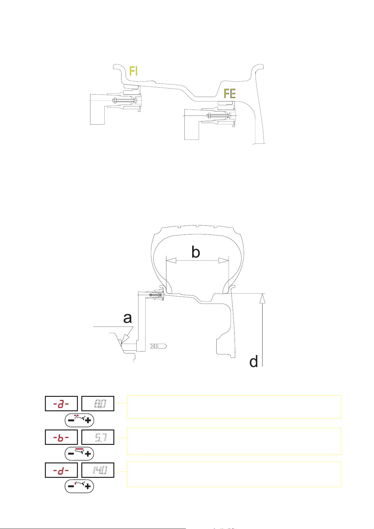
5.2.2 - MANUAL PRESETTING ( C61 )
- Standard wheels
Fig. 8
- Preset distance “a” of the inside of the wheel from the machine.
- Set the rated width, which is generally indicated on the rim, or measure
width “b” using the compass gauge supplied.
- Preset the nominal diameter “d” indicated on the tyre.
I 0184 - 9
GB
Page 10

- Wheel ALU-S
- Measure the dimensions as shown in the following diagram.
Fig. 9
0 Gauge
PRESETTING:
Note: when dE is not set, dE = 0.8 dI is automatic
5.2.3 - SETTING WITH GAUGE EXTENSION ( OPTIONAL C61 )
Extension +6
cm
Fig.A
The extension increases the by 6 cm the gauge distance measurement fi eld (Fig. A) and allows distance
measurement even when the rim has a special profi le (Fig . B).
Proceed as indicated below:
- fi t the extension on the distance gauge
- Measure the distance as already described.
- Read value “a” on the dial and then reset the gauge to “0” and set by hand the value “a + 6”
- Manually set the diameter and the width.
Fig.B
I 0184 - 10
GB
Page 11

5.3 - RECALCULATION OF THE UNBALANCE
Press after new setting of the measurement.
5.4 - MEASUREMENT RESULT
Fig. 10
Inside correction Outside correction
After performing a balancing spin, the amounts of unbalance are shown on the digital readouts.
Digital readouts with LED ‘s 3 - 4 lit up indicate the correct angular wheel position to mount the counterweights (12 o’clock position). If the audible alarm is enabled (see FUNCTION MENU MANAGEMENT),
the acquisition of the correction position sounds with a “beep” alarm.
In the event of unbalance less than the selected threshold value
unbalance value , with it is possible to read the values below the selected threshold gr. by gr.
, is displayed in place of the
I 0184 - 11
GB
Page 12

5.4.1 - INDICATION OF EXACT CORRECTION POSITION ( C61Z )
In ALU 2, ALU 3 and ALU-S correction mode, it is possible to cancel approximations in the mounting of
the counterweights by proceeding as follows:
Fig. 11
- Press button
- fi t the correction weight in the specifi c seat
- pull out the gauge, bearing in mind that the display shows:
to indicate that the gauge should be pulled further out
to indicate that the gauge should be returned to rest position
The left display gives the indications for reaching the position regarding the inside, while the right display
that of the outside.
- bring the wheel into correct angular position for the side selected.
- move the gauge so that the Led comes ON at the correction plane.
- rotate the gauge so that the correction weight adheres to the rim.
- The fact that the weight application position is no longer vertical (Fig.12) is automatically compensated.
Note : it is not possible to apply automatically the correction weight in position as per Fig. 5/Pos.B;
ALWAYS rotate the gauge into position as per Fig. 5/Pos.A.
Fig. 12
I 0184 - 12
GB
Page 13

5.4.2 - SPLIT FUNCTION (unbalance spread)
The SPLIT function is used to position the adhesive weights behind the wheel spokes so that they
are no longer visible. It is advisable to use this function only in the event of static unbalance or in the
ALU S function. Input the wheel dimensions and start the spin. To start the SPLIT function, input the
following data:
Display example prior to
SPLIT function
Input the number of spokes ( 3 ÷ 12 )
30
30
30
15
15
15
30
15
- Move any spoke to the 12 o’clock position
- Place the fi rst Split unbalance in correction position 1
- Correction position 1
- Place the second Split unbalance in correction position 2
- Correction position 2
To return to normal unbalance display, press the button
To perform a new spin, subsequently press the button
I 0184 - 13
GB
Page 14

5.4.3 - UNBALANCE OPTIMIZATION
- This function serves to reduce the amount of weight to be added in
order to balance the wheel
- It is suitable for static unbalance exceeding 30g.
- It improves the residual eccentricity of the tyre.
- Mark with chalk a reference point on the adapter and rim
- With the aid of a tyre remover, turn the tyre on the rim by 180°
- Refi t the wheel with the reference mark coinciding between rim and
adapter
- RH display: percentage reduction
- LH display: actual static unbalance which can be reduced by rotation
TYRE
POSITION
RIM POSITION
- Mark the two positions (rim and tyre) and turn the tyre on the rim until the
positions correspond in order to obtain the optimization on the display
RETURN TO START OF OPTIMIZATION
RETURN TO MEASUREMENT SCREEN
I 0184 - 14
GB
Page 15

5.4.4 - ALU AND STATIC MODES
From the measurement screen, press button to select the type required. The 5-Led displays show
the position where to apply the weights. If a spin has already been performed, the processor automatically
recalculates, for each change of mode, the amounts of unbalance according to the new calculation.
Fig. 13
DYNAMIC Balancing of steel or light alloy rims with application of
clip-on weights on the rim edges.
STATIC The STATIC mode is necessary for motorcycle wheels or
when it is not possible to place the counterweights on
both sides of the rim.
ALU - 1 Balancing light alloy rims by fi tting adhesive weights to
the shoulders of the rim.
ALU - 2 Balancing of light alloy rims with hidden application of the
12/13 mm
support surface
piano appoggio
outer adhesive weights. Outer weight position is fi xed.
ALU - 3 Combined application: clip-on weight inside and hidden adhe-
sive weight on outside (Mercedes). Outer weight position is the
same as ALU-2.
ALU - 4 Combined application: adhesive weight outside and clip-on
weight inside.
5.4.5 - AUTOMATIC MINIMIZATION OF STATIC UNBALANCE
Initial unbalance
Phase shift
Possible approximations
static residual
With conventional
wheel balancer
static residual
static residual
Choice with minimum
static residual
static residual
This program is designed to improve the quality of balancing without any mental effort or loss of time by
the operator. In fact by using the normal commercially available weights, with pitch of 5 in every 5 g, and
by applying the two counterweights which a conventional wheel balancer rounds to the nearest value, there
could be a residual static unbalance of up to 4 g. The damage of such approximation is emphasized by the
fact that static unbalance is cause of most of disturbances on the vehicles. This new function, resident in the
machine, automatically indicates the optimum entity of the weights to be applied by approximating them in
an “intelligent” way according to their position in order to minimize residual static unbalance.
I 0184 - 15
GB
Page 16

6.1 - SELF-DIAGNOSTICS
- All displays, readouts and Led’s should light up in sequence
- Turn the wheel in direction of rotation.
- Turn the wheel in reverse direction of rotation.
- In one complete rev. of the wheel (in direction of rotation) this should appear once:
6 - SET UP
DISPLAY TEST
- Press
- Test parameter
- Displays the sensor distance
values ( C 61Z ) .
- Displays the diameter sensor
values ( C 61Z ) .
END OF SELF-DIAGNOSTICS
CANCEL SELF-DIAGNOSTICS IN
ANY PHASE
I 0184 - 16
GB
Page 17

6.2 - SELF-CALIBRATION
For machine self-calibration proceed as follows :
- Fit a metal wheel of average dimensions on the shaft. Example 6” x 14” (± 1”)
- Preset the exact dimensions of the wheel mounted.
CAUTION!! Presetting of incorrect dimensions would mean that the machine is not correctly calibrated,
therefore all subsequent measurements will be incorrect until a new self-calibration is
performed with the correct dimensions!!
- Perform a spin under normal conditions.
- Add 100 g. (3.5 oz) on the outside in any angular position.
- Shift the 100 g. weight from the outside to the inside keeping the same
angular position.
- Rotate the wheel so to have the 100 g. weight to the 12 o’clock position.
END OF SELF-CALIBRATION
CANCEL SELF-CALIBRATION IN ANY PHASE
I 0184 - 17
GB
Page 18

6.3 - AUTOMATIC GAUGES ( C 61 Z )
6.3.1 - DISTANCE GAUGE
- Place the distance gauge in position and,
holding it fi rmly, press
- Move the gauge to position 15 and press
CORRECT CALIBRATION
- Return the gauge to rest position
- The wheel balancer is ready for operation
Note: In the event of errors or faulty operation, this wording appears on the display
the gauge to position 0 and repeat the calibration operation exactly as described above. If the error
persists, contact the Technical Service Department. In the event of incorrect input in the rim distance
gauge calibration function, press to cancel it.
“CaL.” “P.O.”: shift
6.3.2 - DIAMETER GAUGE
- Currently preset diameter
- Set the required machine calibration value (10 ÷ 18”)
- Press
- Place the gauge tip in the measurement position (Fig.5/
Pos.A)and, holding it down, press
CORRECT CALIBRATION
- Return the gauge to rest position
- The wheel balancer is ready for operation
In the event of incorrect input in the rim diameter gauge calibration function, press to cancel it.
I 0184 - 18
GB
Page 19

7 - ERRORS
During machine operation, various causes of faulty operation could occur. If detected by the microprocessor, they appear on the display as follows:
ERROR MEANING
1 No rotation signal. Could be caused by faulty position transducer, or something
preventing the wheel from turning.
2 During the measurement spins, wheel speed had dropped below 60 r.p.m. Verify
encoder function (see
3 Unbalance too high.
4 Rotation in opposite direction.
5 Guard open before start of spin.
7 Fault in reading the machine calibration parameters. Repeat the self-calibration.
8 Fault in writing the machine calibration parameters. Repeat the self-calibration.
9 General fault in memory of the machine calibration parameters.
Contact Technical Service Department.
11 Speed too high during unbalance measurement spins.
12/13/14 Diffi culty in reading the analogue signal. Check encoder function (see
DIAGNOSTICS
15/17 Inside/outside analogue signal too high. Contact Technical Service Department.
16/18 Inside/outside analogue signal too low. Contact Technical Service Department.
). Contact Technical Service Department.
SELF-DIAGNOSTICS ) and repeat the spin.
SELF-
7.1 - INCONSISTENT UNBALANCE READINGS
Sometimes after balancing a wheel and removing it from the balancing machine, it is found that, upon
mounting it on the machine again, the wheel is not balanced.
This does not depend on incorrect indication of the machine, but only on faulty mounting of the wheel
on the adapter, i.e. in the two mountings the wheel has assumed a different position with respect to the
balancing machine shaft centre line. If the wheel has been mounted on the adapter with screws, it could
be possible that the screws have not been correctly tightened, i.e. crosswise one by one, or else (as often
occurs) holes have been drilled on the wheel with too wide tolerances.
Small errors, up to 10 grams (0.4 oz) are to be considered normal in wheels locked by a cone; the error is
normally greater for wheels fastened with screws or studs.
If, after balancing, the wheel is found to be still unbalanced when refi tted on the vehicles, this could be due
to the unbalance of the car brake drum or very often due to the holes for the screws on the rim and drum
sometimes drilled with too wide tolerances. In such case a readjustment could be advisable using the
balancing machine with the wheel mounted. (For example, our models L36, L38/2).
I 0184 - 19
GB
Page 20

8 - ROUTINE MAINTENANCE
Switch off the machine from the mains before carrying out any operation.
8.1 - REPLACING FUSES
Remove the weight holder shelf to gain access to the power supply board where the fuses are located. If
fuses require replacement, use ones of the same current rating.
If the fault persists, contact Technical Service.
NONE OF THE OTHER MACHINE PARTS REQUIRE MAINTENANCE.
9 - RECOMMENDED SPARE PARTS LIST
(For references, see exploded drawings)
CODE DESCRIPTION
020600503 Bearing 6005 - 2Z Ø 25/47/12
181198630 Spring 19863P
080077007 Rigid belt Poly V - TB2 - 770 - 7 crested
67M38954H Position pick-up board with cable
05PR34147 LEXAN Panel
182185750 Distance gauge spring C61 Z
181206560 Distance gauge spring C61
67M36950A Power board
681002000 Fuses DM5x20 - 2A
511231002 Switch KL 1002 + Q555
86SC52468 Computer board C61Z
86SB36752 Cable, automatic distance gauge C61 Z
86SB36751 Cable, automatic diameter gauge C61 Z
86SB34144 Cable with standard microswitch protection
86SB40113 Cable with 42” microswitch protection
SPECIAL PARTS FOR 230 V MACHINE
501054213
86SZ37439 Complete power board
611000314 Braking transformer 30 VA 230 - 0/50
568001458 Capacitor 10MF 450V Faston screw M8
611000308 Power transformer 30 VA 230 - 9/9
SPECIAL PARTS FOR 115 V MACHINES
502054114
86SZ37440 Complete power board
611000313 Braking transformer 30 VA 115 - 0/25
568002557 Capacitor 25MF 450V FASTON vite/screw M8
611000307 Power transformer 30 VA 115 - 9/9
SPECIFIC SPARE PARTS - CSA STANDARDS
502054117 Single phase motor 4 poles 63/B3 0.18 Kw 115 50/60 Hz
67M36950C Power board ( CSA )
568002540 Capacitor 25MF ( CSA )
611000301 Power transformer 30 VA
611000310 Braking transformer 30 VA
681002001 Fuse 5x20 GMA 2A ( CSA )
Single phase motor BIMA 220-240V/50-60 Hz - 0.18Kw 63/B3-4p.
Single phase motor BIMA 110-115V/50-60 Hz - 0.18Kw 63/B3 - 4p.
I 0184 - 20
GB
 Loading...