


Titan 250
Table of contents
 Loading...
TITAN 250
Turbomachinery Package Specification
Oil & Gas an d P o w e r G e n e r a t i o n Ap p l i c a t i o n s
Generator Set

TURBOMACHINERY PACKAGE
SPECIFICATION
TM
Titan
Solar Turbines Incorporated
P.O. Box 85376
San Diego, CA 92186-5376
250 Generator Set
Caterpillar is a trademark of Caterpillar Inc. Solar, Titan, SoLoNOx, and Turbotronic are trademarks of Solar Turbines
Incorporated. All other trademarks, service marks, or registered trademarks appearing in this specification are the
intellectual property of their respective companies. Specifications are subject to change without notice.
Direct customers of Solar Turbines Incorporated that receive this Turbomachinery Package Specification directly from
Solar Turbines Incorporated may make limited copies of parts of this specification for use in the creation of their own
specification documents. However, such customers shall not distribute any part of this Turbomachinery Package
Specification outside their own organizations for any other purpose. Any other use without the permission of Solar
Turbines Incorporated is strictly prohibited.
© 2008 Solar Turbines Incorporated. All rights reserved. TPS250GS/908 - Preliminary

Turbomachinery Package Specification Titan 250 Generator Set
Table of Contents
1 INTRODUCTION........................................................................................................................5
1.1 General Description ..........................................................................................................5
1.2 Overview ...........................................................................................................................5
2 TITAN 250 GAS TURBINE GENERATOR SET .......................................................................6
2.1 General Description ..........................................................................................................6
2.2 Package Description.........................................................................................................6
2.3 Major Components and Systems......................................................................................6
3 TITAN 250 GAS TURBINE......................................................................................................10
3.1 General Description ........................................................................................................10
4 REDUCTION-DRIVE GEARBOX ............................................................................................13
4.1 General Description ........................................................................................................13
5 GENERATOR AND ASSOCIATED EQUIPMENT..................................................................14
5.1 General Description ........................................................................................................14
5.2 Functional Description ....................................................................................................14
6 START SYSTEM .....................................................................................................................17
6.1 General Description ........................................................................................................17
6.2 Functional Description ....................................................................................................17
6.3 Backup Slow Rotation System........................................................................................18
7 FUEL SYSTEM........................................................................................................................21
7.1 General Description ........................................................................................................21
8 LUBRICATION SYSTEM.........................................................................................................24
8.1 General Description ........................................................................................................24
9 TURBOTRONIC 4 CONTROL SYSTEM.................................................................................29
9.1 Overview .........................................................................................................................29
9.2 System Architecture........................................................................................................29
9.3 Component Descriptions.................................................................................................31
9.4 System Monitoring and Control Functions......................................................................32
9.5 TT4000 Display and Monitoring System.........................................................................34
10 GENERATOR CONTROL AND MONITORING......................................................................40
10.1 General Description ........................................................................................................40
10.2 Generator Control ...........................................................................................................41
11 ENCLOSURE...........................................................................................................................45
11.1 General Description ........................................................................................................45
11.2 Standard Features ..........................................................................................................46
11.3 Optional Features ...........................................................................................................46
12 AIR INLET SYSTEM................................................................................................................52
12.1 General Description ........................................................................................................52
13 EXHAUST SYSTEM................................................................................................................55
13.1 General Description ........................................................................................................55
13.2 Turbine Exhaust Heat Recovery System........................................................................55
14 ACCESSORY EQUIPMENT....................................................................................................57
14.1 DC Power Supply and Battery Charger System.............................................................57
14.2 Turbine Cleaning System................................................................................................57
14.3 Package Lifting Kit ..........................................................................................................59
14.4 Engine Removal Equipment ...........................................................................................59
© 2008 Solar Turbines Incorporated. All rights reserved. TPS250GS/908 - Preliminary
2

Turbomachinery Package Specification Titan 250 Generator Set
15 MARINIZATION.......................................................................................................................61
15.1 General Description ........................................................................................................61
16 QUALITY ASSURANCE AND TESTING................................................................................63
16.1 Quality Assurance...........................................................................................................63
16.2 Testing ............................................................................................................................63
17 PRESERVATION, INSTALLATION, AND DOCUMENTATION.............................................66
17.1 General Description ........................................................................................................66
17.2 Preservation....................................................................................................................66
17.3 Site Requirements ..........................................................................................................66
17.4 Mechanical Installation Requirements............................................................................66
17.5 Documentation................................................................................................................67
18 CERTIFICATION .....................................................................................................................70
18.1 General Description ........................................................................................................70
18.2 National Electrical Code..................................................................................................70
18.3 Canadian Electrical Code ...............................................................................................70
18.4 Conformité Européenne Mark.........................................................................................71
18.5 International Electrotechnical Commission Safety Assessment.....................................72
18.6 Offshore Marine Applications..........................................................................................72
18.7 Summary.........................................................................................................................73
19 SUPPORT SERVICES.............................................................................................................74
19.1 Construction Services .....................................................................................................74
19.2 Customer Services..........................................................................................................74
19.3 Contract Power and Leasing Services............................................................................75
19.4 Solar’s Worldwide Locations...........................................................................................75
CONVERSION CHART..................................................................................................................76
LIST OF ABBREVIATIONS...........................................................................................................77
LIST OF SOLAR’S ENGINEERING SPECIFICATIONS...............................................................80
LIST OF SOLAR’S PRODUCT INFORMATION LETTERS..........................................................80
© 2008 Solar Turbines Incorporated. All rights reserved. TPS250GS/908 - Preliminary
3

Turbomachinery Package Specification Titan 250 Generator Set
Table of Figures
Figure 1. Typical Titan 250 Gas Turbine Generator Set.............................................................6
Figure 2. Typical Titan 250 Generator Set Service Connections (Driver Skid) ..........................8
Figure 3. Titan 250 Two-Shaft Gas Turbine Cutaway ..............................................................10
Figure 4. Typical Combustion Process .....................................................................................11
Figure 5. Typical Reduction Gearbox for the Titan 250 Generator Set....................................13
Figure 6. Typical Open Drip-Proof Generator with Permanent Magnet Exciter System ..........14
Figure 7. Direct-Drive AC Starter Motor and VFD Cabinet.......................................................17
Figure 8. Typical Direct-Drive AC Start System........................................................................18
Figure 9. Turning Gear Assembly.............................................................................................18
Figure 10. Typical Fuel System Schematic ................................................................................21
Figure 11. Typical Lube Oil System............................................................................................26
Figure 12. Typical Onskid Control System..................................................................................30
Figure 13. Typical Offskid Control System..................................................................................30
Figure 14. Turbotronic 4 System Architecture ............................................................................31
Figure 15. Typical TT4000 Operation Summary Display Screen ...............................................35
Figure 16. Typical TT4000 Strip Chart Display...........................................................................35
Figure 17. Typical TT4000S Engine Summary Screen ..............................................................36
Figure 18. Typical TT4000S Generator Summary Screen .........................................................36
Figure 19. Typical Generator, Exciter, and Generator Control Module Arrangement ................41
Figure 20. Typical Generator Metering Panel.............................................................................44
Figure 21. Typical Complete Package Enclosure.......................................................................45
Figure 22. Typical Fire and Gas System.....................................................................................48
Figure 23. Typical CO2 Fire Suppression Cylinders and Cabinets .............................................49
Figure 24. Typical Water Mist Fire Suppression Cylinders and Cabinet ....................................49
Figure 25. Typical Titan 250 Turbine Air Inlet and Exhaust Systems.........................................52
Figure 26. Typical Battery Charger.............................................................................................57
Figure 27. Turbine Cleaning System ..........................................................................................58
Figure 28. Turbine Cleaning Cart................................................................................................58
Figure 29. Separation of Engine Sections ..................................................................................59
Figure 30. Rails and Fixtures for Axial Separation of Engine Sections ......................................59
© 2008 Solar Turbines Incorporated. All rights reserved. TPS250GS/908 - Preliminary
4

Turbomachinery Package Specification Titan 250 Generator Set
1 Introduction
1.1 General Description
Solar Turbines Incorporated is a worldwide leader in the design, manufacture, and
installation of industrial gas turbines. Solar's 40 years of experience integrating high
technology with fluid compression, liquid pumping, power generation, and cogeneration
applications has resulted in more than 12,500 gas turbine installations in 92 countries
around the world. Solar gas turbine packages have logged more than 1.3 billion operating
hours around the world in a wide range of applications. Solar gas turbine packages are
complete operational systems that require a minimum of site preparation prior to
installation.
The Titan 250 generator sets represent years of intensive engineering and manufacturing
design. Solar gas turbines are manufactured to rigid industrial standards and are
thoroughly tested in modern facilities. Solar's operations are certified by Det Norske
Veritas (DNV) to conform to International Standardization Organization (ISO) 9001:2000
Standard for Quality Management Systems.
1.2 Overview
This document describes product features and provides product specification information
for the Titan 250 generator sets. Included are basic package configurations, ancillary
descriptions, installation requirements, and a list of customer support services available
at the time of publication. Please note that changes in equipment, service descriptions,
and specifications may occur without prior notice.
© 2008 Solar Turbines Incorporated. All rights reserved. TPS250GS/908 - Preliminary
5
Turbomachinery Package Specification Titan 250 Generator Set
2 Titan 250 Gas Turbine Generator Set
2.1 General Description
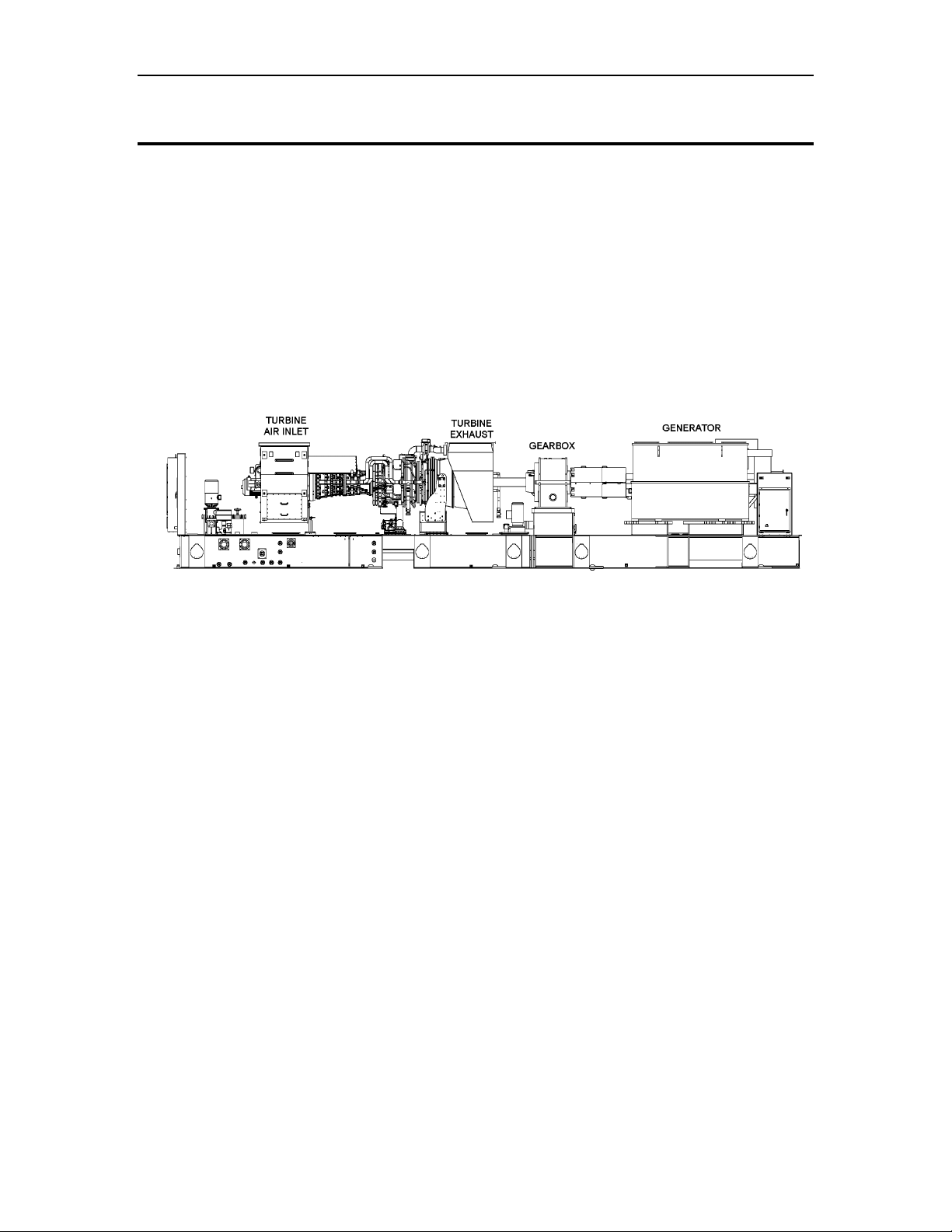
The Titan 250 gas turbine generator set (Figure 1) is a completely integrated and fully
operational package equipped with all accessories and auxiliary systems required for
operation. In addition to the standard package features, a wide array of optional
equipment is available to meet the customer’s installation and operation requirements.
Designed specifically for industrial service, Solar’s gas turbine generator sets are
compact, lightweight, and require minimal floor space for installation. Proven packaging
designs greatly reduce installation costs, time, materials, and labor.
The package features a radial exhaust resulting in a short overall package length that
conserves valuable mounting space.
Figure 1. Typical Titan 250 Gas Turbine Generator Set
2.2 Package Description
The gas turbine generator set consists of an axial-flow gas turbine engine, generator, and
reduction-drive gearbox. These components are installed in-line on a two-piece heavysteel base frame referred to as the skid. The skid is a structural steel assembly with
beam sections and cross members welded together. The two sections of the skid can be
separated to facilitate handling and shipment but when bolted together they form a rigid
structure suitable for three-point mounting. Drip pans are included to collect any potential
liquid leakage. Package connection points for fuel, lube oil, air, and water are located on
the outer edge of the skid.
Electrical connections are made in onskid junction boxes. Machined mounting surfaces
on the skid facilitate component alignment. The gearbox is bolted directly to the engine
and coupled by means of a splined interconnecting drive shaft that eliminates the need
for field alignment. The gearbox and generator are connected by means of a flexible
dry-disk, shear-type coupling enclosed in a coupling guard. Jacking points are provided
to facilitate alignment of the generator to the gearbox.
2.3 Major Components and Systems
Major components and systems of the gas turbine generator set typically include:
• Gas turbine
• Reduction-drive gearbox
• Generator
• Start system
© 2008 Solar Turbines Incorporated. All rights reserved. TPS250GS/908 - Preliminary
6

Turbomachinery Package Specification Titan 250 Generator Set
• Fuel system
• Lubricating oil system
• Turbotronic™ 4 Control System
• Onskid electrical wiring
• Skid with drip pans
• Piping and manifolds
• Ancillary air inlet system
• Ancillary exhaust system
• Package enclosure (if specified) with:
− Ventilation system
− Fire detection and suppression system
− Combustible gas detection system
2.3.1 Package Electrical System
The onskid package electrical system can be furnished to meet the following certification
requirements:
• National Electrical Code (NEC)
• Canadian Electrical Code (CEC)
• Conformité Européenne (CE) Mark
• European Committee for Electrotechnical Standardization (CENELEC)
When supplied, the offskid control console, variable frequency drives, batteries, and
battery charger are not approved for hazardous duty areas and must be installed in a
nonhazardous area.
Three-Phase Motor Voltage
All three-phase motors and three-phase electrical components have the same voltage
rating. Motor starters and contactors are not provided.
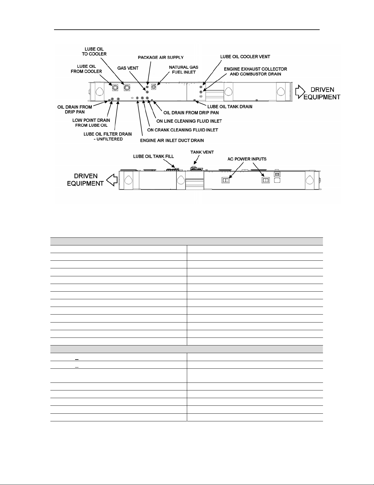
2.3.2 Service Connections
The Titan 250 generator set is supplied with self-contained systems for starting, fuel, lube
oil, and control. All service connections (Figure 2) are conveniently located on the outer
edges of the skid.
© 2008 Solar Turbines Incorporated. All rights reserved. TPS250GS/908 - Preliminary
7
Turbomachinery Package Specification Titan 250 Generator Set
Figure 2. Typical Titan 250 Generator Set Service Connections (Driver Skid)
Table 1. Package Specifications
Dimensions
Approximate Package Measurements
Height, Unenclosed 3.89 m (12 ft 9 in.)
Height, Enclosed 4.12 m (13 ft. 6 in.)
Width (to skid edges) 3.37 m (11 ft 1 in.)
Width (including lifting bollards) 3.60 m (11 ft 10 in.)
Length, Engine Skid 10.29 m (33 ft 9 in.)
Length, Generator Skid
Approximate Package Weights
AC Start Motor Assembly 450 kg (990 lb)
Gas Turbine Assembly 19 050 kg (42,000 lb)
Total Driver (unenclosed package, without oil) 49 900 kg (110,000 lb)
Total Driver (enclosed package, without oil) 57 600 kg (127,000 lb)
Generator (unenclosed)
Piping and Tubing Thickness
Piping > 76.2 mm (3 in.) Nominal Pipe Size (NPS) Schedule 40 (Unless Otherwise Specified)
Piping < 50.8 mm (2 in.) NPS Schedule 80 (Unless Otherwise Specified)
Tubing 3.175 mm (0.125 in.) Nominal Tubing Size
(NTS)
Tubing 6.35 mm (0.25 in.) NTS 1.245 mm (0.049 in.) Minimum Wall Thickness
Tubing 12.7 mm (0.50 in.) NTS 1.651 mm (0.065 in.) Minimum Wall Thickness
Tubing 19.05 mm (0.75 in.) NTS 1.651 mm (0.065 in.) Minimum Wall Thickness
Tubing 25.40 mm (1.00 in.) NTS 2.108 mm (0.083 in.) Minimum Wall Thickness
Tubing 31.75 mm (1.25 in.) NTS 2.768 mm (0.109 in.) Minimum Wall Thickness
0.889 mm (0.035 in.) Minimum Wall Thickness
© 2008 Solar Turbines Incorporated. All rights reserved. TPS250GS/908 - Preliminary
8

Turbomachinery Package Specification Titan 250 Generator Set
Construction Materials
Piping, Manifolds, and Tubing < 10.2 cm (4 in.)
Note (a)
Piping, Manifolds, and Tubing > 10.2 cm (4 in.)
Note (a)
Piping Interface Connections 316L Stainless Steel (Unless Otherwise Specified)
Flange Assembly Hardware 316L Stainless Steel
Pipe Support Brackets
Pipe Flexible Couplings
Tubing Dual Ferrule Compression Fittings 316L Stainless Steel
Sliding Lube Oil Drain Couplings and Plates
Lube Oil Vent Flame Arrestor Aluminum
Electrical System Certifications
NEC Class 1, Group D, Division 1 or 2
CENELEC Zone 1 or 2, Group II
CE, ATEX Zone 2, Group II
Three-Phase Package Motors
Optional Motor Voltage Ratings
Single-Phase Battery Charger
Optional Battery Charger Voltage Ratings
Single-Phase Lighting and Space Heater Voltage
Optional Package Lighting and Space Heater
Voltage Ratings
316L Stainless Steel (Unless Otherwise Specified)
Carbon Steel (Unless Otherwise Specified)
Carbon Steel (Standard)
316L Stainless Steel (Optional)
Carbon Steel (Standard)
316L Stainless Steel (Optional)
Carbon Steel (Standard)
316L Stainless Steel (Optional)
380, 400, or 415 VAC, 50 Hz
460 VAC 60 Hz
220, 230, 240, 380, 400, 415, 440, 460, or 480
VAC, 50 Hz or 60 Hz
120, 220, 230, or 240 VAC, 50 Hz or 60 Hz
Ingress Protection (IP) Ratings
Onskid Junction Boxes IP56 to IP66
Control Console IP50
Battery Charger, NEC IP22
Battery Charger, CE IP31
Solar’s Applicable Engineering Specifications
ES 9-56 Fusion Welding
ES 9-58 Standard Paint Program – Turbomachinery
ES 1593
ES 1762
ES 2201 Auxiliary Air
ES 2231
Solar’s Applicable Product Information Letters
PIL 127 Product Certification
Notes:
(a) All package piping is fabricated from 316L stainless steel with the exception of lube oil vent
lines and any piping welded directly to a carbon steel lube oil tank or tank cover.
Guidelines for NEC Compliance of Solar’s Product Lines: Class I, Group D, Division 1
and Division 2
Standards and Practices for Electrical Systems for Gas Turbine Packages Installed In
Hazardous Areas (CENELEC/IEC Standards – European ATEX Directive 94/9/EC)
Standards and Practices for The Design and Installation of Cable Channels and TC
Rated Cables Installed In Class 1, Division 2 Hazardous Areas
© 2008 Solar Turbines Incorporated. All rights reserved. TPS250GS/908 - Preliminary
9
Turbomachinery Package Specification Titan 250 Generator Set
3 Titan 250 Gas Turbine
3.1 General Description
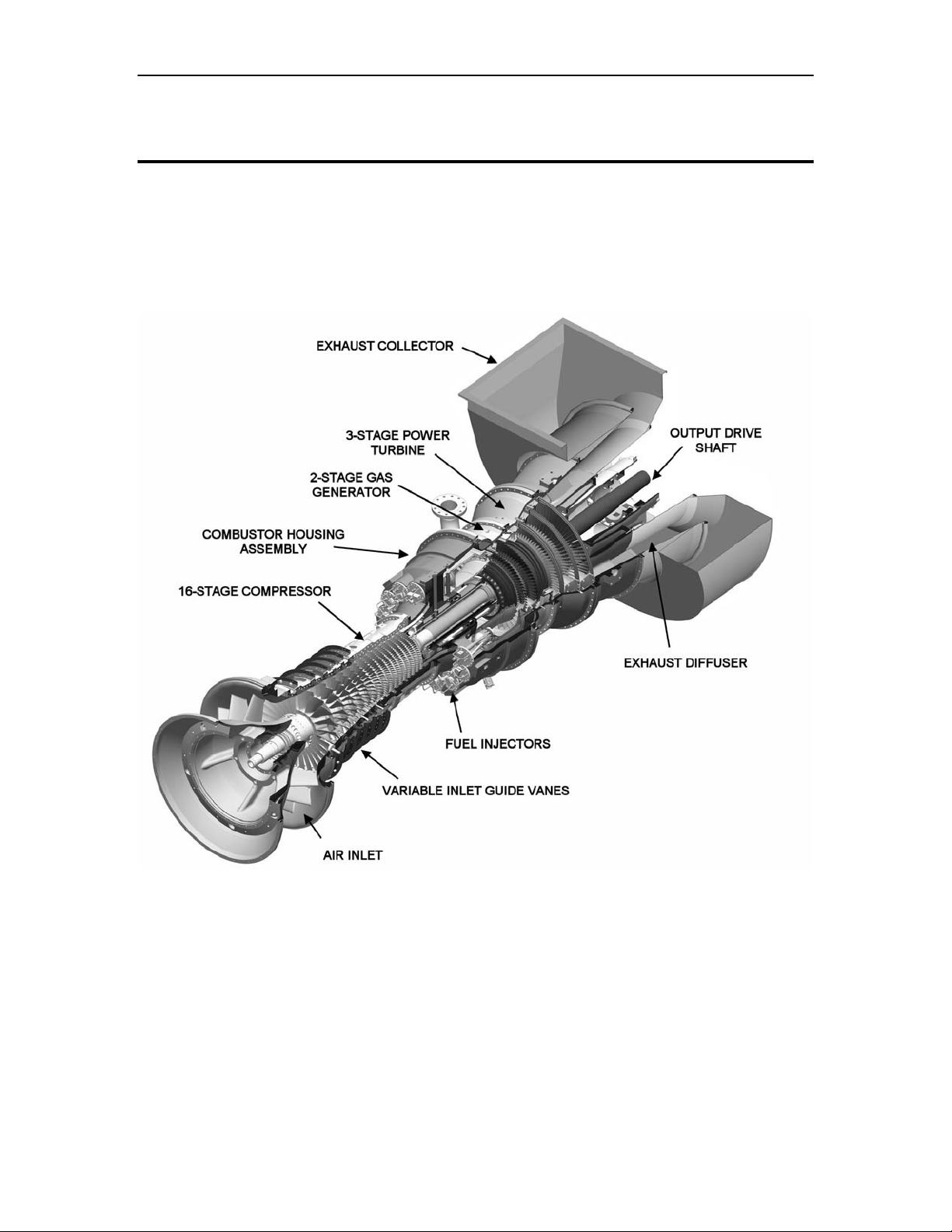
The two-shaft Titan 250 gas turbine (Figure 3) is a completely integrated and selfcontained prime mover. The Titan 250 gas turbine combines high performance operation
with rugged industrial construction. This design philosophy allows for high efficiency, low
maintenance, and a long service life. The Titan 250 gas turbine is designed for a high
degree of compliance with American Petroleum Institute (API) requirements.
Figure 3. Titan 250 Two-Shaft Gas Turbine Cutaway
3.1.1 Principles of Operation
During the typical combustion process (Figure 4), air is drawn into the gas turbine air inlet
and is compressed by the multi-stage, axial-flow engine compressor. The compressed air
is directed into the annular combustion chamber at a steady flow. Fuel is injected and
mixed with the compressed air and ignited during the start cycle. Continuous combustion
will be maintained as long as there is an adequate flow of pressurized air and fuel. Hotpressurized gas from the combustor expands through and drives the turbine, dropping in
pressure and temperature as it exits the turbine. This combustion cycle converts the
energy in the fuel into kinetic rotating power at the turbine output shaft.
© 2008 Solar Turbines Incorporated. All rights reserved. TPS250GS/908 - Preliminary
10

Turbomachinery Package Specification Titan 250 Generator Set
For combustion, the gas turbine requires approximately one-fourth of the total air it
compresses. The excess air is mixed with the combustion products to reduce the gas
temperature at the turbine first stage-inlet. The cooling air also keeps metal temperatures
in the combustor and turbine assembly relatively low to ensure a long service life.
Figure 4. Typical Combustion Process
3.1.2 SoLoNOx Combustion System
The Titan 250 incorporates Solar’s proprietary SoLoNOx dry emissions system that
reduces pollution by limiting the formation of nitrous oxides (NOx), carbon monoxide
(CO), and unburned hydrocarbons (UHC). This system uses lean premix combustion to
lower the maximum flame temperature and reduce pollution formation. Solar’s
engineering staff will work with the customer to meet local permitting emission
requirements.
Table 1. Titan 250 Gas Turbine Specifications
Compressor
Type Axial Flow
Number of Stages 16
Compression Ratio 24:1
Flow (Nominal) 67.3 kg/sec (148 lb/sec)
Speed, Maximum 10,500 rpm
Combustion Chamber
Type Annular
Ignition Torch
Number of Fuel Injectors 14 (SoLoNOx, Low Emissions)
Gas Generator
Type Axial
Number of Stages 3
Power Turbine
Type Axial
Number of Stages 2
Speed 7000 rpm
Bearings
Radial 5 Tilt Pad with Proximity Probes
Thrust
2 Tilt Pad with Resistance Temperature Device
Probes
© 2008 Solar Turbines Incorporated. All rights reserved. TPS250GS/908 - Preliminary
11
Turbomachinery Package Specification Titan 250 Generator Set
Construction Materials
Compressor Case
- Forward Section Nodular Iron
- Aft Section WC6 Alloy Steel
Combustor Case 410 Stainless Steel
Exhaust Diffuser Nodular Iron
Accessory Gear Housing Ductile Iron
Protective Coatings
Compressor Rotor and Stator Blades Inorganic Aluminum
Nozzles, First and Second Stage Precious Metal Diffusion Aluminide
Blades, First and Second Stage Precious Metal Diffusion Aluminide
Approximate Weight
Gas Turbine Assembly 19 050 kg (42,000 lb)
Performance
Output Power Note (a)
22 370 kW (30,000 hp)
Heat Rate 9000 kJ/ kW-hr (6360 Btu/ kW-hr)
Exhaust Flow 245 660 kg/hr (541,590 lb/hr)
Exhaust Temperature 465°C (865°F)
Temperature Monitoring
Turbine T5 (12) Thermocouples
Vibration Monitoring
Turbine Bearing #1 Displacement Probes, X and Y axis
Turbine Bearing #2 Displacement Probes, X and Y axis
Turbine Bearing #3 Displacement Probes, X and Y axis
Turbine Bearing #4 Displacement Probes, X and Y axis
Turbine Bearing #5 Displacement Probes, X and Y axis
Gas Producer Rotor Shaft Displacement Probe, Axial Position
Power Turbine Rotor Shaft Displacement Probe, Axial Position
Gas Producer Rotor Shaft Keyphasor
Power Turbine Rotor Shaft Keyphasor
Accessory Gearbox Velocity Pickup
Notes:
(b) Performance is calculated under the following conditions:
Nominal Rating - ISO at 15°C (59°F), Sea Level
No Inlet/Exhaust Losses
Relative Humidity at 60%
LHV = 31.5 to 43.3 MJ/nm
3
(800 to 1,100 Btu/scf)
© 2008 Solar Turbines Incorporated. All rights reserved. TPS250GS/908 - Preliminary
12
Turbomachinery Package Specification Titan 250 Generator Set
4 Reduction-Drive Gearbox
4.1 General Description
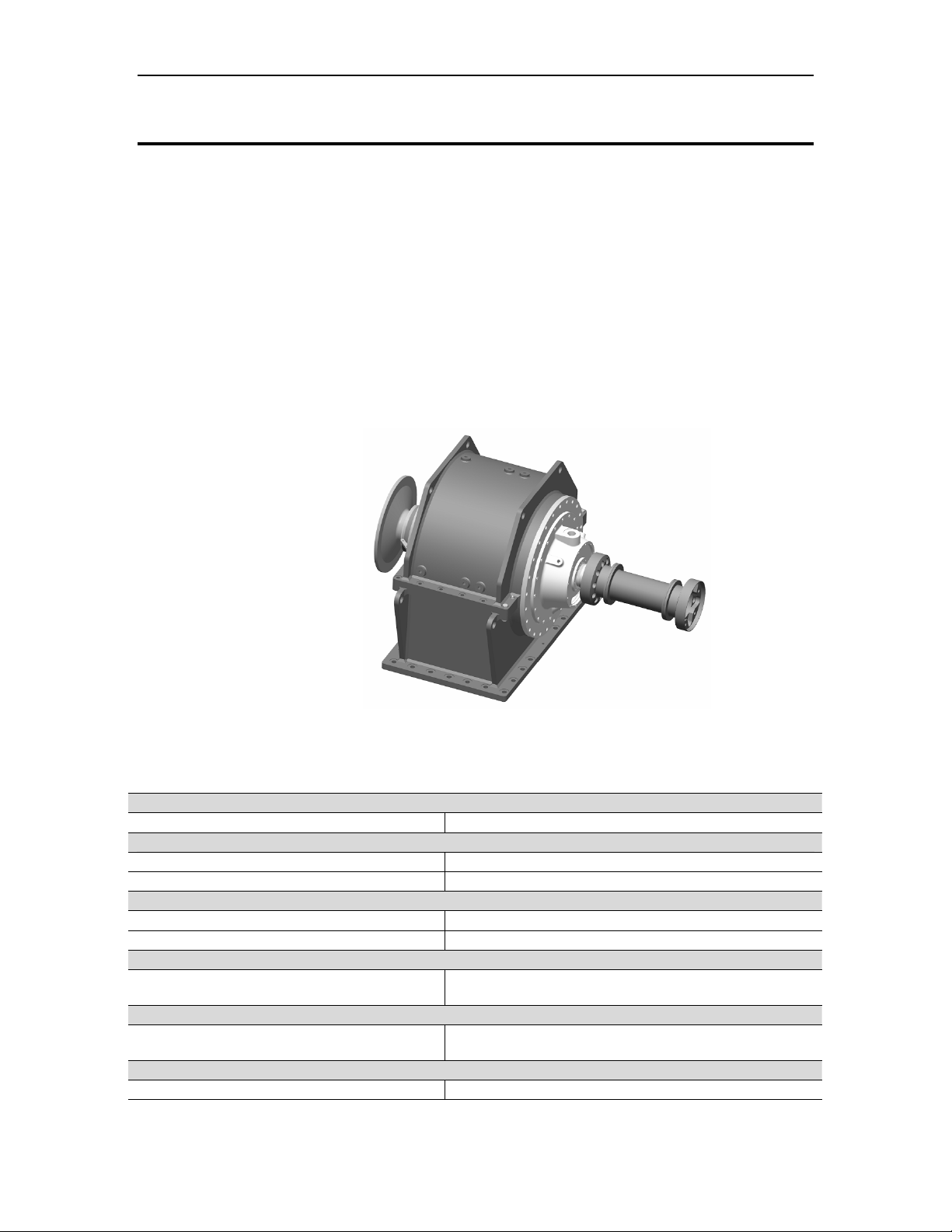
The reduction-drive gearbox (Figure 5) is an industrial, epicyclic, star-gear design
selected specifically for generator set applications. The gearbox uses few moving parts,
which provides high reliability and ease of assembly and disassembly. The reduction
gearbox is designed for continuous-duty operation and reduces the output speed of the
turbine to the required operating speed of the generator. The gearbox is coupled to the
gas turbine through a balanced high-speed shaft, splined at both ends. The output shaft
is coupled to the generator through a flexible disk-type dry coupling enclosed in a
coupling guard. The design of the gearbox facilitates straight-through shafting, avoiding
offset problems and permitting engine, gear, and generator alignment from a common
base. Gear lubrication is provided by the package lube oil system.
The gearbox is designed to provide 99% reliability between major inspections and
overhauls.
Figure 5. Typical Reduction Gearbox for the Titan 250 Generator Set
Table 2. Reduction-Drive Gearbox Specifications
Approximate Weight
Gearbox 7300 kg (16,100 lb)
Output Speed
50 Hz Service 1500 rpm
60 Hz Service 1800 rpm
Inspection and Overhaul Intervals
Major Inspection Interval 30,000 hours
Overhaul Interval 100,000 hours
Compliance
American Petroleum Institute (API)
Ratings
American Gear Manufacturers Association
(AGMA)
Vibration Monitoring
Gearbox Acceleration Probe
© 2008 Solar Turbines Incorporated. All rights reserved. TPS250GS/908 - Preliminary
613 Compliant With Exceptions, Refer to Solar’s
Standard List of Exceptions
In Excess of 1.10 for Generator Applications
13
Turbomachinery Package Specification Titan 250 Generator Set
5 Generator and Associated Equipment
5.1 General Description
For maximum flexibility, the gas turbine package can be provided with several different
generator types and voltage outputs to accommodate a broad range of application
requirements. The generator, exciter, and control system are integrated to provide
optimal performance.
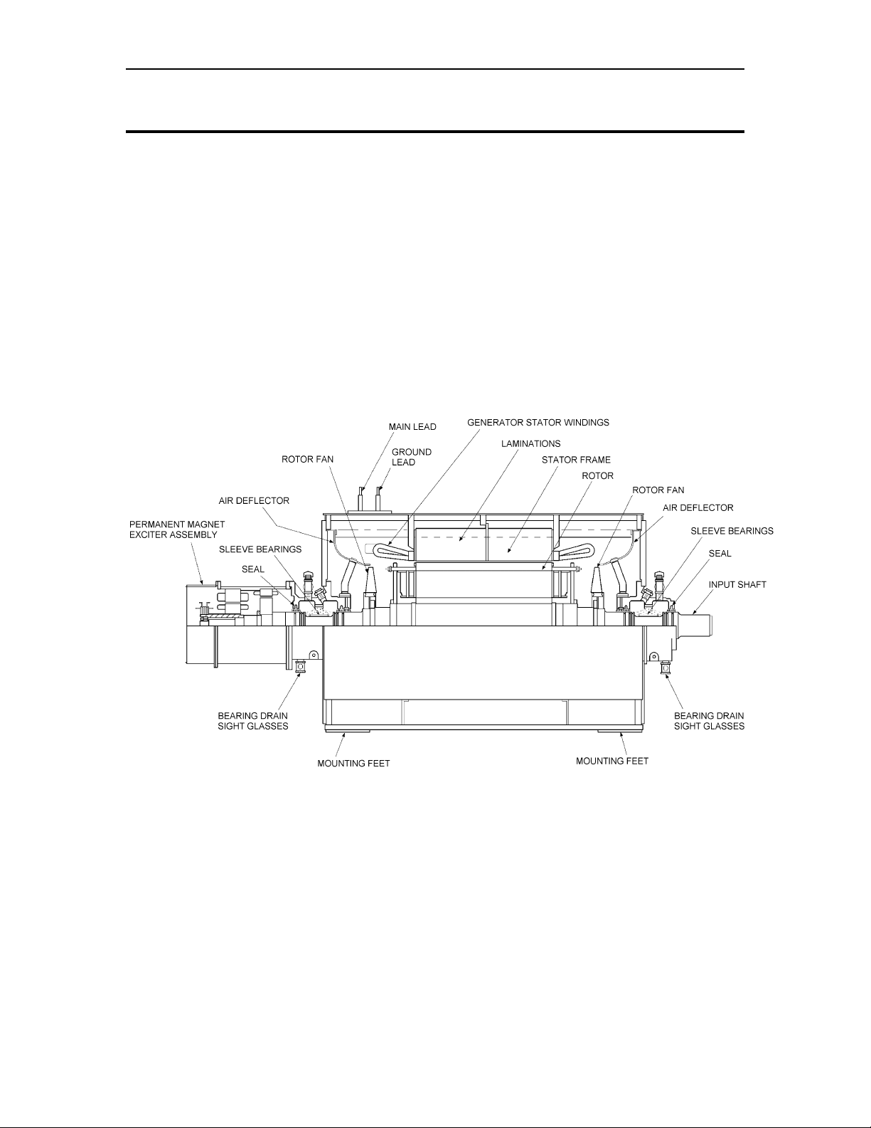
The standard generator type supplied is open drip-proof (ODP) (Figure 6). However the
following other enclosure types are available to meet a variety of environmental
conditions and cooling requirements:
• Closed air circuit air cooled (CACA)
• Closed air circuit water-to-air cooled (CACW)
• Totally enclosed air-to-air cooled (TEAAC)
• Totally enclosed water-to-air cooled (TEWAC)
Figure 6. Typical Open Drip-Proof Generator with Permanent Magnet Exciter System
5.2 Functional Description
During generator operation, three-phase AC power generated by the exciter armature is
converted to DC power by a rectifier. The DC output from the rectifier is applied as field
excitation current to the generator rotor windings to create magnetic flux. The generator
voltage output is controlled by the generator field current and the generator field current
is controlled by a brushless exciter. The amount of DC current applied to the exciter field
determines the exciter output voltage. A potential transformer senses the bus potential
and provides a signal to the combined generator control module (CGCM) for excitation
control.
© 2008 Solar Turbines Incorporated. All rights reserved. TPS250GS/908 - Preliminary
14

Turbomachinery Package Specification Titan 250 Generator Set
Any variations in bus potential will also be sensed and corrected by this circuit. After
voltage builds, the generator accelerates to 100% speed and excitation and voltage
control is assumed by the CGCM. A crosscurrent-compensating transformer provides the
signal to the CGCM for reactive loadsharing between multiple paralleled units.
It should be noted that the generator rotor windings rotate and the generator armature is
stationary. The exciter field coils are also stationary and the exciter armature rotates with
the main generator rotor shaft. As a result, a single rotating assembly consisting of the
exciter armature, exciter rectifier, and the generator rotor windings is formed. This single
rotating assembly greatly simplifies all electrical connections within the generator.
5.2.1 Standard Features
Generators include the following standard features:
• Sleeve bearings with pressure fed sumps
• Terminal box
• Form wound stator windings
• Amortisseur windings
• Rotor balance to 125% rated speed
• Anti-condensation space heaters
• Permanent magnet generator (PMG)
• Rotating armature-type VAC exciter
• Full-wave rectifier assembly
Special order generators are available to meet unique customer requirements including
non-U.S. specifications.
5.2.2 Rotor
The salient, four-pole, forged rotor is dynamically balanced to minimize vibration. Motor
fans move cooling air through the generator and around the rotor. The rotors have
layer-wound field windings cemented with a high-strength resin and are baked to cure the
resin. The rotor is in electrical and mechanical balance at all speeds up to 125% of rated
speed.
5.2.3 Stator
The stator is built with high-grade silicon steel laminations that are precision-punched and
individually insulated. Windings are typically form-wound and treated with thermosetting
synthetic varnish or vacuum pressure impregnated (VPI) epoxy for maximum moisture
resistance, high dielectric strength, and high bonding qualities. The windings are braced
to withstand shock loads such as motor starting and short circuits. Space heaters can be
supplied to minimize condensation during shutdowns.
5.2.4 Shaft
The shaft diameter provides the necessary stiffness to avoid torsional vibration. The
turbine-driven generator set is given a complete torsional analysis.
5.2.5 Frame
The frame is heavy-duty steel and is fabricated with deep welds and internal reinforcing
for extra rigidity and strength. The frame also includes lifting lugs.
5.2.6 Exciter
Excitation current for the generator field coils is provided by a brushless rotating exciter
with a PMG pilot exciter. The exciter is mounted directly on the generator rotor shaft. The
exciter consists of two basic parts, a small three-phase, AC generator with rotating
© 2008 Solar Turbines Incorporated. All rights reserved. TPS250GS/908 - Preliminary
15

Turbomachinery Package Specification Titan 250 Generator Set
armature and a three-phase, full-wave, diode-type bridge rectifier that rotates with the
armature. The pilot exciter is a PMG that rotates with the main generator rotor shaft. It
feeds the exciter field windings with excitation current and is controlled by the CGCM.
5.2.7 Bearing Lubrication System
The generator is supplied with a force-fed bearing lubrication system consisting of onskid
piping and a filter strainer. Oil is supplied from the package lube oil system.
Table 3. Generator and Associated Equipment Specifications
Approximate Weight
Generator (Typical Open Drip Proof) 45 000 kg (99,200 lb)
Construction Types
Open Drip Proof (OPD), Air Cooled Standard
Closed Air Circuit Water-to-Air Cooled (CACW) Optional
Closed Air Circuit, Air Cooled (CACA) Optional
Totally Enclosed Air-to-Air Cooled (TEAAC) Optional
Totally Enclosed Water Air Cooled (TEWAC) Optional
Generator
Optional Voltage Ratings See Note (a)
Frequency Ratings 50 or 60 Hz
Number of Poles 4
Number of Leads 6
Connection Wye
Stator Windings Form Wound
Insulation
Temperature Rise See Note (b)
Overload Capacity
Overload Compliance NEMA
Short Circuit Capability 300% For 10 seconds
Rotor Balance To 125% of Rated Speed
Maximum Wave Form Deviation 10%
Maximum Harmonic Content 3%
Telephone Influence Factor (TIF)
Balanced 100
Residual 75
Efficiency
Space Heater
Voltage 120, 220, 230, or 240 VAC
Frequency 50 or 60 Hz
Phase 1 Phase
Vibration Monitoring
Generator Bearing Driven End Displacement Probes, X and Y axis
Generator Bearing Exciter End Displacement Probes, X and Y axis
Notes:
(a) Other voltages can be provided to meet specific customer requirements.
(b) A 80°C (144°F) temperature rise is based on the generator nameplate rating at 40°C (104°F)
and a power factor of 0.8 for continuous duty service.
11,000, 12,470, or 13,800 VAC,
National Electrical Manufacturers Association
(NEMA) Class F
NEMA Class B,
-150% Rated Current for One Minute
-110% Rated Current for Two Hours
The combined generator, exciter, and regulator
efficiency at full load is nominally 97%.
© 2008 Solar Turbines Incorporated. All rights reserved. TPS250GS/908 - Preliminary
16
Turbomachinery Package Specification Titan 250 Generator Set
6 Start System
6.1 General Description
The start system includes a direct-drive AC starter motor driven by a solid-state variable
frequency drive (VFD). The start system provides torque to initiate engine rotation and to
assist the engine in reaching a self-sustaining speed. The starter motor is mounted
directly on the gas turbine accessory drive gearbox. The VFD regulates voltage and
frequency to the starter motor for engine rotation as commanded by the Turbotronic 4
control system.
6.2 Functional Description
To begin gas turbine rotation, the VFD initially provides low-frequency AC power to the
starter motor. The VFD gradually increases the speed of the starter motor until the gas
turbine reaches purging speed. When purging is completed, the control system activates
the fuel system. The speed of the starter motor is gradually increased until the gas
turbine reaches starter dropout speed. The VFD then deenergizes the starter motor and
the motor clutch assembly is disengaged.
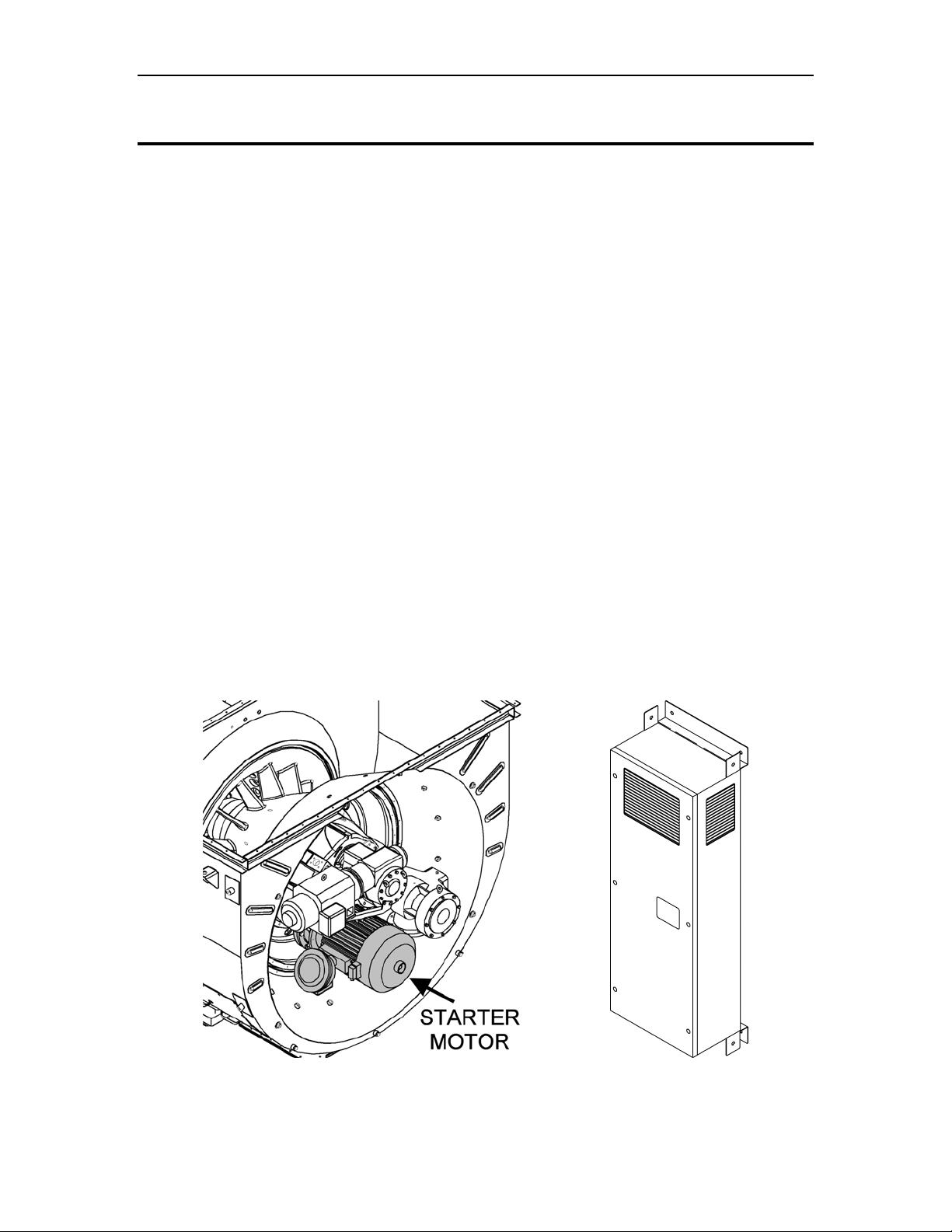
6.2.1 Starter Motor
The starter motor (Figure 7) provides high breakaway starting torque and acceleration
from standstill to starter dropout speed. The motor is standard frame size and is
constructed to be explosion proof and flameproof. The motor includes an integral
over-temperature protection thermostat connected to the Turbotronic 4 control system for
hazardous area motor certification and protection. Separate cable entry points are
provided for power connections, thermal protection wiring, and the space heater wiring.
Starting power is transferred to the gas turbine via the reduction-drive gearbox and overrunning clutch and shaft assembly. After a shutdown, the starter motor rotates the turbine
at low speed to prevent deformation of the rotor during cool down.
Figure 7. Direct-Drive AC Starter Motor and VFD Cabinet
© 2008 Solar Turbines Incorporated. All rights reserved. TPS250GS/908 - Preliminary
17
Turbomachinery Package Specification Titan 250 Generator Set
6.2.2 Variable Frequency Drive
The VFD (Figure 7) is a motor speed controller that provides pulse-width modulated
power with variable frequency and voltage to the starter motor. Controlled by the
Turbotronic 4 control system, the VFD regulates voltage and frequency to the starter
motor to control engine speed from standstill to starter dropout speed. The system is
capable of performing up to six start attempts per hour, as well as extended purge cycles
for heat recovery unit applications and engine wash cycles. The VFD cabinet is designed
for installation in a non-hazardous location. Electrical disconnects and overcurrent
protection devices are not provided.
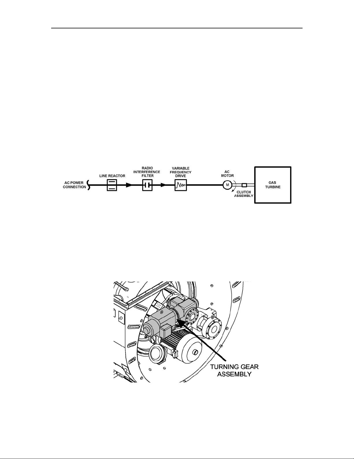
6.2.3 Power Wiring
The start system (Figure 8) requires customer-furnished, three-phase AC input.
Additional three-phase AC power wiring is required to connect the VFD to the starter
motors. A start contactor is not required for VFD operation. A customer-furnished fused
disconnect at the VFD input is recommended. Optional motor space heater wiring is
available.
Figure 8. Typical Direct-Drive AC Start System
6.3 Backup Slow Rotation System
The Titan 250 package is equipped with a DC powered turning gear system (Figure 9) to
ensure low speed rotation of the turbine as backup for the DAC starter motor in the event
of loss of AC power to the package. The system engages the decelerating turbine at low
speed and maintains rotation for a specified time.
Figure 9. Turning Gear Assembly
© 2008 Solar Turbines Incorporated. All rights reserved. TPS250GS/908 - Preliminary
18

Turbomachinery Package Specification Titan 250 Generator Set
Table 4. Start System Specifications
Variable Frequency Drive
Optional Voltage Input Ranges See Note (a)
Minimum Input Current
- 380 to 460 VAC Input 525 amps
- 500 to 600 VAC Input 342 amps
Voltage Output Range 0 to 460 VAC, (0 to 240 Hz)
Maximum Line Distribution Capacity 1000 kVa
Maximum Fault Current Capacity See Note (b)
Maximum Breakaway Amperage 383 amps
Maximum Breakaway Torque 918 N-m (677 ft-lb)
Power Factor 0.96
Efficiency 98%
Minimum/Maximum Operating Temperature
Heat Rejection
- 380 to 460 VAC Input 7350 watts
- 500 to 600 VAC Input 9485 watts
Input Fuse Rating 600 amp
Approximate Measurements
- Height 220 cm (87 in.)
- Width 69 cm (24 in.)
- Depth 60 cm (28 in.)
Approximate Weight 28 831 kg (850 lb)
- Length 73 cm (29 in.)
- Diameter 46 cm (18 in.)
Starter Motor
Motor Type Squirrel-cage Induction
Motor Voltage Rating 380 AC, (0 to 133 Hz)
Power 93 kW (125 hp)
Operating Speed 0 to 7000 rpm
Maximum Breakaway Amperage 659 amps
Maximum Breakaway Torque 488 N-m (360 ft-lb)
Minimum/Maximum Operating Temperature
Space Heater Voltage 115 VAC, 60 Hz
Approximate Measurements
- Length 66 cm (26 in.)
- Diameter 45.7 cm (18 in.)
Approximate Weight
- AC Starter Motor Assembly 450 kg (990 lb)
Power Wiring
VFD to Starter Motors Power Cable Length
Turning Gear Motor
Motor Type Squirrel-cage Induction
Motor Voltage Rating 240 VDC
Power 3.73 kW (5 hp)
Operating Speed 2500 rpm
Turbine Rotation Speed 300 rpm
380 to 460 VAC, (48 to 62 Hz)
500 to 600 VAC, (48 to 62 Hz)
30 000 amps
-10 to 40°C (14 to 104°F)
-40 to 60°C (-40 to 140°F)
38 m (123 ft), See Note (c)
© 2008 Solar Turbines Incorporated. All rights reserved. TPS250GS/908 - Preliminary
19

Turbomachinery Package Specification Titan 250 Generator Set
Applicable Engineering Specifications
Solar’s Engineering Specification ES 1593
Solar’s Engineering Specification ES 1762
Applicable Product Information Letters
Solar’s Product Information Letter PIL 149 Direct-drive AC Start Systems
Notes:
(a) If the customer-furnished input voltage is greater than 600 VAC ±5%, a step-down
transformer is recommended.
(b) Feeder circuits exceeding this limit require the use of an isolation transformer, line reactor, or
other means of adding similar impedance to limit fault current.
(c) Longer cable runs may require an onskid marshalling box and/or output line reactor.
Guidelines for NEC Compliance of Solar Product
Lines: Class I, Group D, Division 1 and Division 2
Standards and Practices for Electrical Systems For
Gas Turbine Packages Installed in Hazardous Areas
(CENELEC Standards)
© 2008 Solar Turbines Incorporated. All rights reserved. TPS250GS/908 - Preliminary
20
Turbomachinery Package Specification Titan 250 Generator Set
7 Fuel System
7.1 General Description
The fuel system (Figure 10), in conjunction with the control system, includes all
necessary components to control ignition and fuel flow during all modes of operation.
TP
LEGEND
TP = PRESSURE TRANSMITTER
RT = RTD (TEMPERATURE)
VS = VALVE SOLENOID
PILOT
FUEL
CONTROL
VALVE
TP
PILOT FUEL
MANIFOLD
TO FUEL
INJECTORS
GAS VENT
VENT
VALVE
TP
SECONDARY
SHUT OFF
VALVE
V
S
FUEL
AIR
TP
V
S
PRIMARY
SHUT OFF
VALVE
VS VS
Figure 10. Typical Fuel System Schematic
7.1.1 SoLoNOx Combustion System
The SoLoNOx combustion system uses special fuel injectors with main and pilot fuel
ports. The fuel injected through these ports is controlled during starting and steady-state
operation to maintain stable combustion and minimize the formation of nitrous oxides
(NOx), carbon monoxide (CO), and unburned hydrocarbon (UHC) emissions. To further
regulate emission levels, combustion airflow is regulated using a bleed valve mounted on
the combustor case. The SoLoNOx combustion system also includes an additional inlet
gas filter/coalescer for mounting offskid.
TORCH
REGULATOR
TORCH SHUT
OFF VALVE
TP
MAIN
FUEL
CONTROL
VALVE #1
TPRT
MAIN
FUEL
CONTROL
VALVE #2
TP
TORCH
REGULATOR
TP
TP
TP
MAIN FUEL
MANIFOLD
#1
MAIN FUEL
MANIFOLD
#2
TO FUEL
INJECTORS
TO FUEL
INJECTORS
TO TORCH
7.1.2 Fuel System
The SoLoNOx fuel system includes:
• Supply pressure transmitter
• Pilot air operated primary gas fuel shutoff valve
• Pilot air operated secondary gas fuel shutoff valve
• Pilot air operated gas vent valve
• Electrically operated fuel control valves (2)
• Torch with shutoff valve and pressure regulators
• Main fuel manifold
• Fuel injectors
© 2008 Solar Turbines Incorporated. All rights reserved. TPS250GS/908 - Preliminary
21

Turbomachinery Package Specification Titan 250 Generator Set
• Fuel pilot control valve
• Fuel pilot manifold
• Inlet gas filter/coalescer loose shipped for field installation
Component Operation
The gas fuel pressure supplied to the turbine skid must meet minimum and maximum
pressure and flow requirements. If the gas fuel pressure is too high or too low, the control
system will prevent turbine operation. Pneumatically actuated primary and secondary gas
fuel shutoff valves are controlled using pilot air pressure. For each valve, pilot air
pressure is admitted to and exhausted from a pneumatic actuator through a solenoid
valve. Fail-safe operation ensures both valves will close in case pilot air pressure is lost.
The gas fuel control valves and the SoLoNOx fuel pilot control valve, are powered by
integrated DC motor-driven actuators. Integrated actuator electronics provide precise
closed-loop valve control based on position command inputs versus position feedback
outputs. The three valves are fast acting and provide fuel metering for light-off,
acceleration, full load, and load transient conditions. Fail-safe operation ensures both
valves will close in case the command signal or control power is lost. During the start
sequence prior to ignition, the control system will verify gas pressure and perform a gas
valve check to verify proper operation of all gas fuel valves.
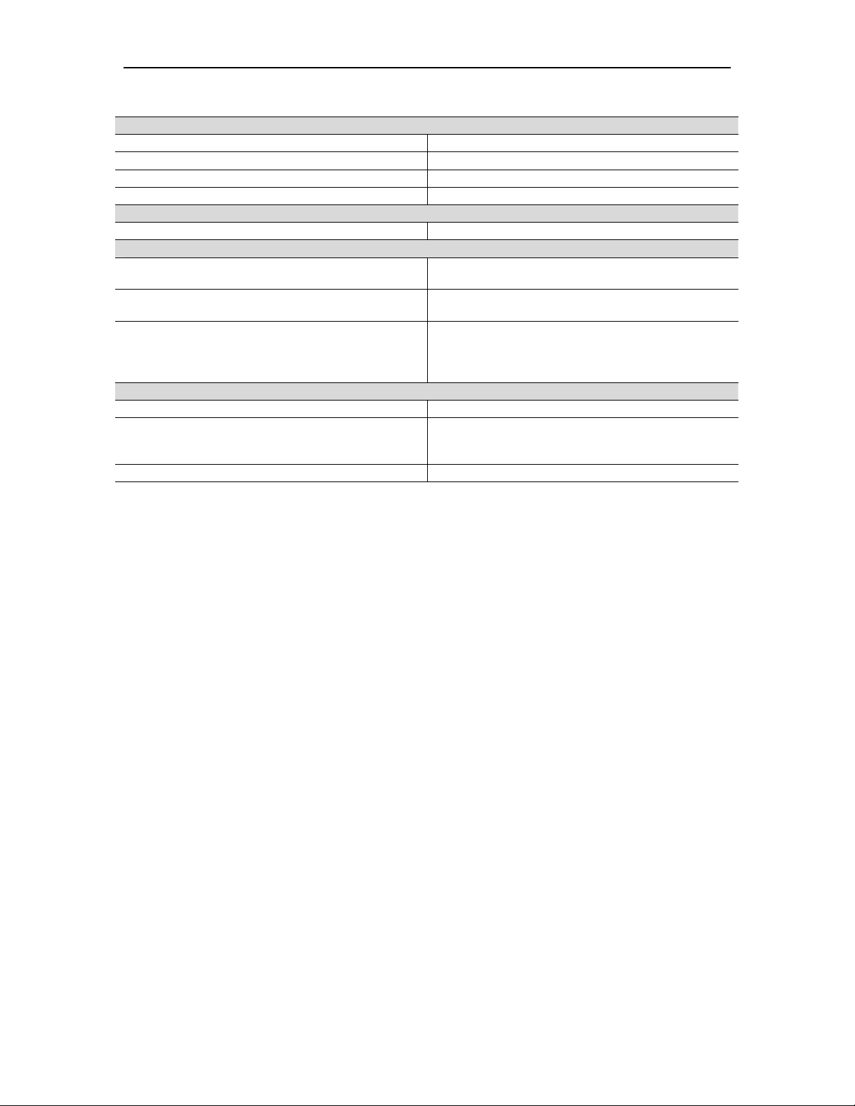
Table 5. Fuel System Specifications
Gas Fuel System
Acceptable Gas Fuels See Note (a)
Fuel Quality Refer to Solar’s Engineering Specification ES 9-98
Compliance
Minimum/Maximum Gas Fuel Supply Pressure
Minimum Flow Rate 3513 to 5480 kg/hr (7746 to 12086 lbm/hr), See
Minimum/Maximum Fuel Supply Temperature
Primary Gas Fuel Shutoff Valve Pneumatically Actuated Spring-Closed Ball Valve
Secondary Gas Fuel Shutoff Valve Pneumatically Actuated Vane Type Valve
Gas Fuel Control Valve and SoLoNOx Fuel Pilot
Control Valve
Actuator Voltage 120 VDC
Valve Discrete Signals 0 to 24 VDC
Valve Analog Signals 4 to 20 mA
Maximum Operating Pressure 4137 kPag (600 psig)
Maximum Operating Temperature 93°C (200°F)
Response Time Less Than 100 msec From 10-to-90% Stroke
Valve Body
Gas Fuel Filter (Conventional Units Only) 10 Micron
Offskid Coalescing Filter Module (SoLoNOx Units
Only)
Maximum Operating Pressure 3447 kPag (500 psig)
Maximum Flow 122 m3/min (4300 ft3/min)
Minimum/Maximum Operating
Temperatures
Filtration Efficiency β0.3 > 200 per ISO 4572
Natural Gas
Propane
Butane
National Association of Corrosion Engineers
(NACE) Compliant
2240 to 3447 kPag (325 to 500 psig), See Note (b)
Note (b)
-40 to 93°C (-40 to 200°F), See Note (c)
Actuator Valve
Aluminum (Standard)
Stainless Steel (Optional)
-29 to 100°C (-20 to 212°F)
© 2008 Solar Turbines Incorporated. All rights reserved. TPS250GS/908 - Preliminary
22
Turbomachinery Package Specification Titan 250 Generator Set
Customer-Furnished Pilot Air System
Fluid Clean-Dry Air
Air Quality
Minimum/Maximum Regulated Pressure Range 689 to 1379 kPag (100 to 200 psig)
Pilot Air Filter 10 micron
Construction Materials
Piping, Manifolds, and Tubing 316L Stainless Steel
Applicable Engineering Specifications
Solar’s Engineering Specification ES 9-98
Solar’s Engineering Specification ES 1593
Solar’s Engineering Specification ES 1762
Applicable Product Information Letters
Solar’s Product Information Letter PIL 148 LPG and NGL Fuels
Solar’s Product Information Letter PIL 162
Solar’s Product Information Letter PIL 176 Siloxanes in Gas Fuel
Notes:
(a) The gas fuel system is designed to operate with fuels that comply with Solar’s Engineering
Specification ES 9-98. Most commercially available natural gas fuels comply with ES 9-98.
The gas fuel system can be modified to operate with fuels that do not comply with ES 9-98.
Solar gas turbines can operate on low Btu fuels. Please contact Solar Turbines for
assistance in evaluating fuel characteristics and gas turbine requirements.
(b) Fuel pressure and flow requirements can be affected by several factors such as; fuel
temperature, fuel lower heating value, air inlet temperature, fuel composition, fuel specific
gravity, engine injector type, inlet duct loss, relative humidity, site elevation, and piping length
and diameter. Based on site conditions, minimum fuel pressure and flow requirements may
be less than stated values. Please contact Solar Turbines for site-specific fuel pressure and
flow requirements.
(c) Fuel must have a differential temperature (ΔT) of at least 27°C (50°F) above fuel dew point
temperature.
(d) The particle size in the air stream should not exceed 10μ. Since it is impractical to remove
100% of all particles larger than 10μ, this is defined as ß10 > 100, or 99% efficient. Oil or
hydrocarbon content should not exceed 1 ppm. The dew point at line pressure shall be at
least 6°C (10°F) below the minimum temperature to which any part of the air system is
exposed or between -29°C and 93°C (-20°F and 200°F). Air should be free of all corrosive
contaminants, hazardous gases, flammables, and toxics.
See Note (d)
Fuel, Air, and Water (or Steam) for Solar Gas
Turbine Engines
Guidelines for NEC Compliance of Solar Product
Lines: Class I, Group D, Division 1 and Division 2
Standards and Practices for Electrical Systems for
Gas Turbine Packages Installed In Hazardous
Areas (CENELEC/IEC Standards – European
ATEX Directive 94/9/EC)
Recommendations for the Sourcing, Handling,
Storage and Treatment of Fuels for Solar Gas
Turbines
© 2008 Solar Turbines Incorporated. All rights reserved. TPS250GS/908 - Preliminary
23

Turbomachinery Package Specification Titan 250 Generator Set
8 Lubrication System
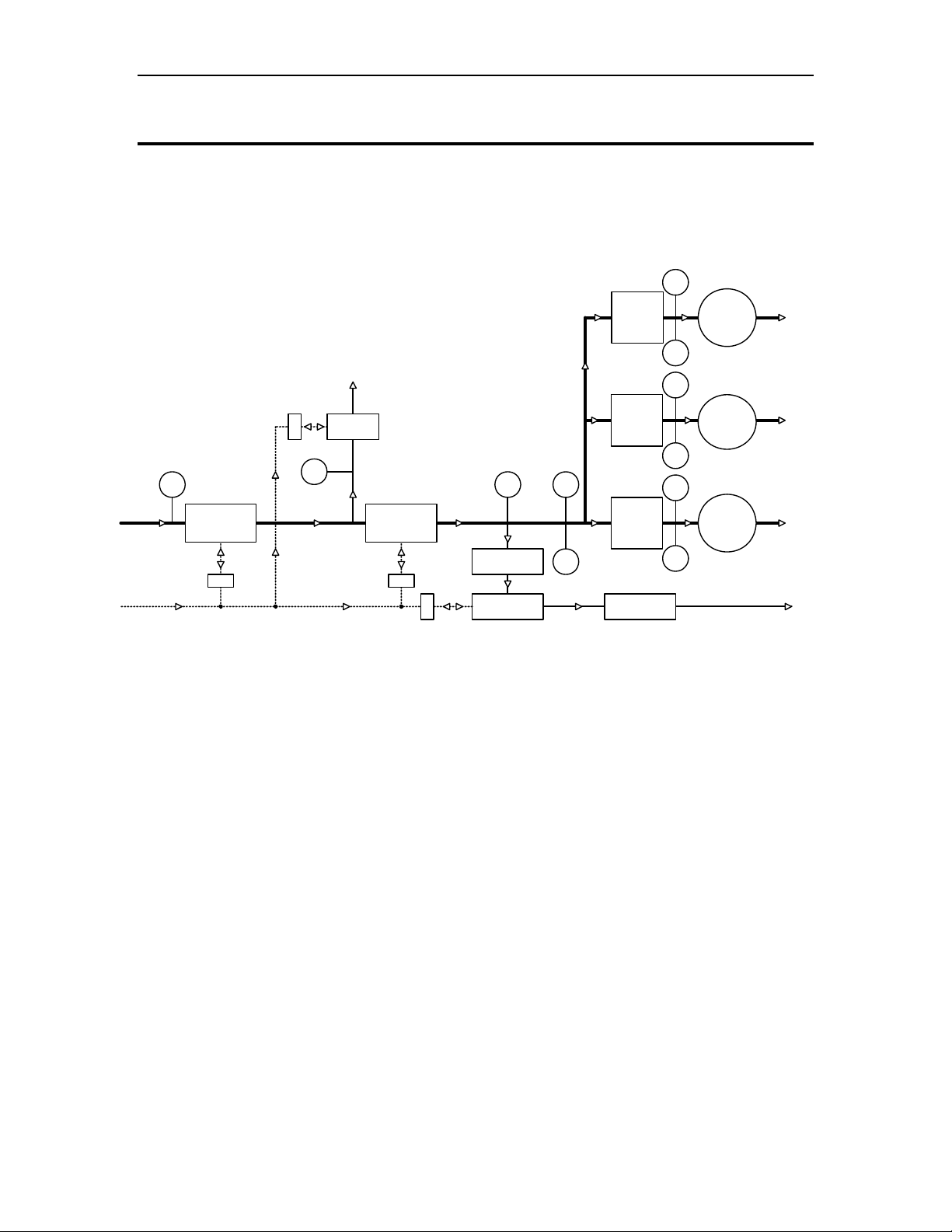
8.1 General Description
The lubrication system, (Figure 11) circulates oil under pressure to the gas turbine and
driven equipment. Lube oil is supplied from the lube oil tank located in the driver frame.
Oil temperature is maintained at optimal levels by a thermostatic control valve, oil tank
heater, and optional oil cooler.
The lubrication system incorporates the following components:
• Oil tank
• Oil tank heater
• Lube oil (customer furnished)
• Gas turbine driven main lube oil pump
• AC Motor-driven pre/post lube oil pump
• DC Motor-driven backup lube oil pump
• Duplex lube oil filter system with replaceable elements
• Oil level, pressure, and temperature indications
• Pressure and temperature regulators
• Strainers
• Oil tank vent separator
• Oil tank vent flame trap
Optional features include:
• Offskid oil cooler
• Stainless steel oil tank and tank covers
• Stainless steel filter system
8.1.1 Lube Oil
Lube oil is customer furnished. Petroleum base or synthetic oil with a viscosity grade of
C32 or C46 may be used. Synthesized hydrocarbon oils are recommended due to lower
pour point, higher viscosity index, better heat transfer, and lower oxidation rate. Lube oil
must conform to Solar’s Engineering Specification ES 9-224.
8.1.2 Gas Turbine-Driven Main Lube Oil Pump
The main lube oil pump is mounted on an integral accessory drive gearbox. This
positive-displacement pump provides lube oil pressure for normal operation.
8.1.3 AC Motor-Driven Pre/Post Lube Oil Pump
The pre/post lube oil pump provides lube oil pressure during package starting and for
post-lube cooling of the gas turbine and driven equipment bearings. The pre/post lube oil
pump provides lube oil pressure during a gas turbine roll down in the event the main lube
oil pump has failed.
8.1.4 DC Motor-Driven Backup Lube Oil Pump
The backup lube oil pump provides lube oil pressure for post lube cooling of the gas
turbine and driven equipment bearings in the event the pre/post lube oil pump fails. The
backup lube oil pump provides lube oil pressure during a gas turbine roll down in the
event the main lube oil pump and pre/post lube oil pump have both failed. The backup
lube oil pump also provides lube oil pressure during an emergency condition such as a
© 2008 Solar Turbines Incorporated. All rights reserved. TPS250GS/908 - Preliminary
24
Loading...