


Operation
Maintenance
Manual
966C WHEEL LOADER

Shutdown SIS
Previous Screen
 Product: WHEEL LOADER
Model: 966C WHEEL LOADER 9KC
Configuration: 966C WHEEL LOADER / POWER SHIFT / 9KC00001-UP (MACHINE) POWERED BY 3306 ENGINE
Operation and Maintenance Manual
966C AND 966R WHEEL LOADERS
Media Number -SEBU6290-00 Publication Date -01/02/1990 Date Updated -11/10/2001
Foreword
This manual contains safety, operation, transportation, lubrication and maintenance information.
Some photographs or illustrations in this publication show details or attachments that may be different from your machine. Guards and covers may have been removed for illustrative purposes.
Continuing improvement and advancement of product design may have caused changes to your machine which are not included in this publication. Read-study-and keep it with the machine.
Whenever a question arises regarding your machine, or this publication, please consult your Caterpillar dealer for the latest available information.
Safety
The safety section lists basic safety precautions. In addition, this section identifies the text and locations of warning labels used on the machine.
Read and understand the basic precautions listed in the safety section before operating or performing lubrication, maintenance and repair on this product.
Operation
The operation section is a reference for the new operator and a refresher for the experienced one. This section includes a discussion of gauges, switches, machine controls, attachment controls, transportation and towing information.
Photographs and illustrations guide the operator through correct procedures of checking, starting, operating and stopping the machine.
Operating techniques outlined in this publication are basic. Skill and techniques develop as the operator gains knowledge of the machine and its capabilities.
Maintenance
The maintenance section is a guide to equipment care. The illustrated, step-by-step instructions are grouped by servicing intervals. Items without specific intervals are listed under "When Required" topics. Items in the "Maintenance Intervals" chart are referenced to detailed instructions that follow.
Maintenance Intervals

Use the service hour meter to determine servicing intervals. Calendar intervals shown (daily, weekly, monthly, etc.) may be used instead of service hour meter intervals if they provide more convenient servicing schedules and approximate the indicated service hour meter reading. Recommended service should always be performed at the interval that occurs first.
Under extremely severe, dusty or wet operating conditions, more frequent lubrication than is specified in the "Maintenance Interval" chart may be necessary.
Perform service on items at multiples of the original requirement. For example, at "Every 500 Service Hours or 3 Months", also service those items listed under "Every 250 Service Hours or Monthly", "Every 50 Service Hours or Weekly" and "Every 10 Service Hours or Daily."
Machine Description
This rubber tired bucket machine is equipped with a Caterpillar 3306 diesel engine. The primary use of this machine is for moving material.
Copyright 1993 - 2022 Caterpillar Inc. |
Mon Dec 19 2022 17:26:28 GMT+0700 (Indochina Time) |
|||
All Rights Reserved. |
||||
|
||||
Private Network For |
SIS Licensees. |
|
|
|
Shutdown SIS
Previous Screen
 Product: WHEEL LOADER
Model: 966C WHEEL LOADER 9KC
Configuration: 966C WHEEL LOADER / POWER SHIFT / 9KC00001-UP (MACHINE) POWERED BY 3306 ENGINE
Operation and Maintenance Manual
966C AND 966R WHEEL LOADERS
Media Number -SEBU6290-00 Publication Date -01/02/1990 Date Updated -11/10/2001
Safety
Warning Signs and Labels
There are several specific safety signs on your machine. Their exact location and description of the hazard are reviewed in this section. Please take the time to familiarize yourself with these safety signs.
Make sure that you can read all safety signs. Clean or replace these if you cannot read the words or see the pictures. When cleaning the labels use a cloth, water and soap. Do not use solvent, gasoline, etc.
You must replace a label if it is damaged, missing or cannot be read. if a label is on a part that is replaced, make sure a new label is installed on the replaced part. See your Caterpillar dealer for new labels.
Do not operate or work on the machine unless you have read and understand the instructions and warnings in the Operations and Maintenance Manual. Failure to follow the instructions or heed the warnings could result in injury or death. Contact any Caterpillar dealer for replacement manuals. Proper care is your responsibility.
Located in the cab.
Structural damage, an overturn, modification, alteration, or improper repair can impair this structure's protection capability thereby voiding this certification. Consult a Caterpillar dealer to determine this structure's limitations without voiding its certification.
Located on the ROPS or FOPS.
Improper jumper cable connections can cause an explosion resulting in personal injury. Batteries in series may be located in separate compartments. When using jumper cables always connect positive (+) cable to positive (+) terminal of battery connected to starter solenoid and negative (-) cable from external source to starter negative (-) terminal. (If not equipped with starter negative terminal, connect to engine block.)
Located in the battery compartment.
No clearance for man in this area when machine turns; Severe injury or death from crushing could occur.
Connect steering frame lock link between front and rear frames before lifting machine, transporting machine on another vehicle, or performing service near center of machine.
Disconnect steering frame lock link and secure to retaining plates before resuming operation or machine will not steer.
Located on the machine at the center pivot.
General Hazard Information
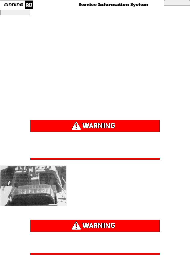
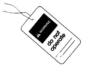
Attach a "DO NOT OPERATE" or similar warning tag to start switch or controls before servicing or repairing the machine. These tags, Form SEHS7332, are available from your Caterpillar dealer.
Wear a hard hat, protective glasses and other protective equipment as required by job conditions. Do not wear loose clothing or jewelry that can catch on controls or other parts of the machine. Make certain all protective guards and covers are secured in place on the machine.
Keep the machine, especially the deck, walkways and steps, free of foreign material, such as debris, oil, tools and other items which are not part of the machine.
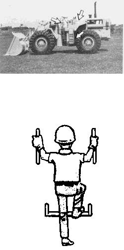
Secure all loose items such as lunch boxes, tools and other items which are not part of the machine. Know the appropriate work-site hand signals and who gives them. Accept signals from one person only. Never put maintenance fluids into glass containers.
Use all cleaning solutions with care.
Report all needed repairs.
Do not allow unauthorized personnel on the machine.
Perform all maintenance unless otherwise specified as follows:
*The machine parked on level ground.
*The bucket controls in HOLD.
*The transmission control in NEUTRAL.
*The parking/secondary brake engaged.
*The engine stopped.
*The key start switch off and the key removed.
*The disconnect switch off and the key removed.
Pressure Air
Pressure air can cause personal injury. When using pressure air for cleaning, wear a protective face shield, protective clothing and protective shoes.
The maximum air pressure must be below 205 kPa (30 psi) for cleaning purposes.
Fluid Penetration
Always use a board or cardboard when checking for a leak. Escaping fluid under pressure, even a pin-hole size leak, can penetrate body tissue, causing serious injury, and possible death. If fluid is injected into your skin, it must be treated by a doctor familiar with this type of injury immediately.
Asbestos Information
Caution should be used to avoid breathing dust that may be generated when handling components containing asbestos fibers. If this dust is inhaled, it can be hazardous to your health. Components in Caterpillar products that may contain asbestos fibers are brake pads, brake band and lining assemblies, clutch plates and some gaskets. The asbestos used in these components is usually bound in a resin or sealed in some way. Normal handling is not hazardous as long as airborne dust which contains asbestos is not generated.
If dust which may contain asbestos is present, there are several common sense guidelines that should be followed.
*Never use compressed air for cleaning.
*Avoid brushing or grinding of asbestos containing materials.
*For clean up, use wet methods or a vacuum equipped with a high efficiency particulate air (HEPA) filter.
*Use exhaust ventilation on permanent machining jobs.
*Wear an approved respirator if there is no other way to control the dust.
*Comply with applicable rules and regulations for the work place (for example in the U.S.A., OSHA requirements as set forth in 29 CFR 1910.1001).
*Follow environmental rules and regulations for disposal of asbestos.
*Avoid areas where asbestos particles may be in the air.
Crushing or Cutting Prevention
Support equipment and attachments properly when working beneath them. Do not depend on hydraulic cylinders to hold it up. Any attachment can fall if a control is moved, or if a hydraulic line breaks.
Never attempt adjustments while the machine is moving or the engine is running unless otherwise specified.
Where there are attachment linkages, the clearance in the linkage area will increase or decrease with movement of the attachment.
Stay clear of all rotating and moving parts.
Keep objects away from moving fan blades. They will throw or cut any object or tool that falls or is pushed into them.
Do not use a kinked or frayed wire rope cable. Wear gloves when handling the wire rope cable.
Retainer pins, when struck with force, can fly out and injury nearby persons. Make sure the area is clear of people when driving retainer pins.
Wear protective glasses when striking a retainer pin to avoid injury to your eyes.
Chips or other debris can fly off objects when struck. Make sure no one can be injured by flying debris before striking any object.
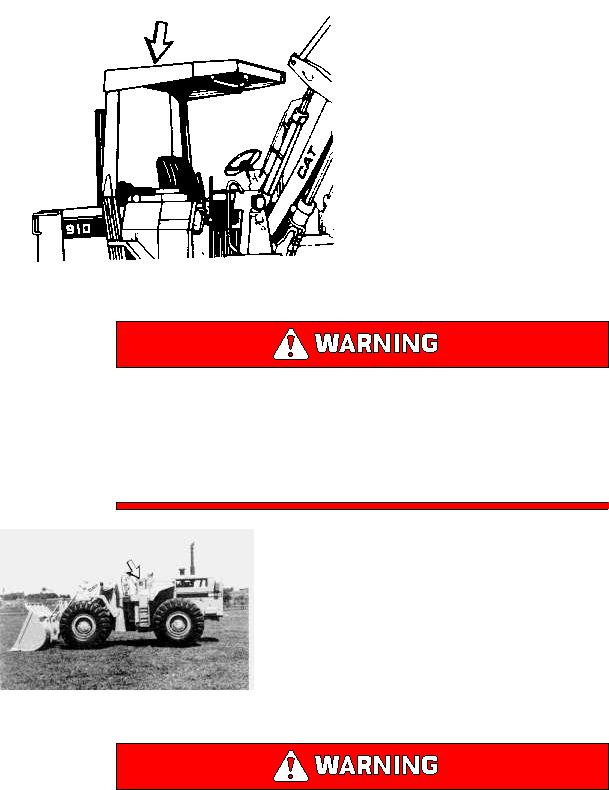
Rollover Protective Structure (ROPS) or Falling Objects Protective Structure (FOPS) - (If Equipped)
This is an attached guard located above the operator's compartment and secured to the machine.
To avoid possible weakening of the Rollover Protective Structure (ROPS) or Falling Objects Protective Structure (FOPS), consult a Caterpillar dealer before altering the ROPS (FOPS) in any way. The protection offered by this ROPS (FOPS) will be impaired if it has been subjected to structural damage. Structural damage can be caused by an overturn accident, by falling objects, etc.
Burn Prevention
Coolant
At operating temperature, the engine coolant is hot and under pressure. The radiator and all lines to heaters or the engine contain hot water or steam. Any contact can cause severe burns.
Steam can cause personal injury.
Check the coolant level only after the engine has been stopped and the filler cap is cool enough to remove with your bare hand.
Remove the cooling system filler cap slowly to relieve pressure.
Cooling system additive contains alkali that can cause personal injury. Avoid contact with the skin and eyes and do not drink.
Allow cooling system components to cool before draining.
Oils
Hot oil and components can cause personal injury. Do not allow hot oil or components to contact the skin. At operating temperature, the hydraulic tank is hot and can be under pressure.
Remove the hydraulic tank filler cap only after the engine has been stopped and the filler cap is cool enough to remove with your bare hand.
Remove the hydraulic tank filler cap slowly to relieve pressure.
Relieve all pressure in air, oil, fuel or cooling systems before any lines, fittings or related items are disconnected or removed.
Batteries
Batteries give off flammable fumes which can explode.
Do not smoke when observing the battery electrolyte levels.
Electrolyte is an acid and can cause personal injury if it contacts skin or eyes.
Always wear protective glasses when working with batteries.
Fire or Explosion Prevention
All fuels, most lubricants and some coolant mixtures are flammable.
Fuel leaked or spilled onto hot surfaces or electrical components can cause a fire.
Do not smoke while refueling or in a refueling area.
Do not smoke in areas where batteries are charged, or where flammable materials are stored.
Batteries in series may be located in separate compartments. When using jumper cables always connect positive
(+) cable to positive (+) terminal of battery connected to starter solenoid and negative (-) cable from external
source to starter negative (-) terminal. (If not equipped with starter negative terminal, connect to engine block.)
See the "Operation Section" of this manual for specific starting instructions.
Clean and tighten all electrical connections. Check daily for loose or frayed electrical wires. Have all loose or frayed electrical wires tightened, repaired or replaced before operating the machine.
Keep all fuels and lubricants stored in properly marked containers and away from all unauthorized persons.
Store all oily rags or other flammable material in a protective container, in a safe place.
Do not weld or flame cut on pipes or tubes that contain flammable fluids. Clean them thoroughly with nonflammable solvent before welding or flame cutting on them.
Remove all flammable materials such as fuel, oil and other debris before they accumulate on the machine.
Do not expose the machine to flames, burning brush, etc., if at all possible.
Shields, which protect hot exhaust components from oil or fuel spray in the event of a line, tube or seal failure, must be installed correctly.
Have a fire extinguisher available and know how to use it. Inspect and have it serviced as recommended on its instruction plate.
Ether
Ether is poisonous and flammable.
Breathing ether vapors or repeated contact of ether with skin can cause personal injury.
Use ether only in well ventilated areas.
Do not smoke while changing ether cylinders.
Use ether with care to avoid fires.
Do not store replacement ether cylinders in living areas or in the operator's compartment.
Do not store ether cylinders in direct sunlight or at temperatures above 39°C (102°F).
Discard cylinders in a safe place. Do not puncture or burn cylinders.
Keep ether cylinders out of the reach of unauthorized personnel.
Lines, Tubes and Hoses
Do not bend or strike high pressure lines. Do not install bent or damaged lines, tubes or hoses.
Repair any loose or damaged fuel and oil lines, tubes and hoses. Leaks can cause fires. Contact your Caterpillar dealer for repair or replacement.
Check lines, tubes and hoses carefully. Do not use your bare hand to check for leaks. Use a board or cardboard to check for leaks. See "Fluid Penetration" in the "Safety" section for more details. Tighten all connections to the recommended torque. Replace if any of the following conditions are found.
*End fittings damaged or leaking.
*Outer covering chafed or cut and wire reinforcing exposed.
*Outer covering ballooning locally.
*Evidence of kinking or crushing of the flexible part of hose.
*Armouring embedded in the outer cover.
*End fittings displaced.
Make sure that all clamps, guards and heat shields are installed correctly to prevent vibration, rubbing against other parts, and excessive heat during operation.
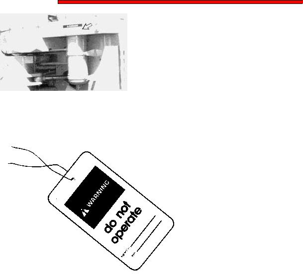
Tire Information
Explosions of air-inflated earthmoving tires have resulted from heat-induced gas combustion inside the tires. The heat, generated by welding or heating rim components, external fire, or excessive use of brakes can cause gaseous combustion.
A tire explosion is much more violent than a blowout. The explosion can propel the tire, rim and axle components as far as 500 m (1500 ft) or more from the machine. Both the force of the explosion and the flying debris can cause personal injury or death, and property damage.
Do not approach a tire closer than the outside of the area represented by the shaded area in the above drawing.
Dry nitrogen (N2) gas is recommended for inflation of tires. If the tires were originally inflated with air, nitrogen is still preferred for adjusting the pressure. Nitrogen mixes properly with air.
Nitrogen inflated tires reduce the potential of a tire explosion, because nitrogen does not support combustion. Also, nitrogen helps prevent oxidation and the resulting deterioration of rubber and corrosion of rim components.
Proper nitrogen inflation equipment and training in its use are necessary to avoid overinflation. A tire blowout or rim failure can result from improper or misused equipment.
Stand behind the tread and use a self-attaching chuck when inflating a tire.
Servicing and changing tires and rims can be dangerous and should be done only be trained personnel using proper tools and procedures. If correct procedures are not followed while servicing tires and rims, the assemblies could burst with explosive force and cause serious personal injury or death. Follow carefully the specific information provided by your tire or rim servicing man or dealer.
Mounting and Dismounting
*Mount and dismount the machine only where steps and/or handholds are provided.
*Inspect, and when necessary, clean and have repairs made to steps and handholds before mounting and dismounting.
*Face the machine when mounting and dismounting.
*Maintain a three point contact (two feet and one hand or one foot and two hands contact) with the steps and handholds.
*Never get on or off a moving machine.
*Never jump off the machine.
*Do not try to climb on or off the machine when carrying tools or supplies. Use a hand line to pull equipment up onto the platform.
*Do not use any controls as handholds when entering or leaving the operator's station.
Secondary Exit
Machines equipped with cabs are equipped with secondary exits. For additional secondary exit information, refer to topics "Right Cab Window" and "Cab Rear Window" in the "Monitoring Systems and Cab Features" section of this manual.
Before Starting the Engine
Start the engine only from the operator's station. Never short across the starter terminals or across the batteries, as this could bypass the engine neutral-start system as well as damage the electrical system.
Inspect the condition of the seat belt and mounting hardware. Replace any damaged or worn parts. Replace the seat belt regardless of appearance, after three years of use.
Adjust the seat so that full pedal travel can be obtained with the operator's back against the seat back.
Make sure the machine is equipped with a lighting system as required by conditions.
Make sure all lights are working properly.
Make sure no one is working on, underneath or close to the machine before starting the engine or beginning to move the machine. Make sure the area is free of personnel.
Engine Starting
Do not start the engine or move any of the controls if there is a "DO NOT OPERATE" or similar warning tag attached to the start switch or controls.
Move all hydraulic controls to the HOLD position before starting the engine.
Move the transmission control lever to NEUTRAL.
Engage the parking/secondary brake.
Start and operate the engine in a well ventilated area only. In an enclosed area, vent the exhaust to the outside.
Before Operating the Machine
Clear all personnel from the machine and the area.
Clear all obstacles from the path of the machine. Beware of hazards such as wires, ditches, etc. Be sure all windows are clean. Secure the doors and windows in either the open or shut position. Adjust the rear view mirrors (if equipped) for best vision, especially close to the machine.
Make sure the machine horn, the backup alarm (if equipped) and all other warning devices are working properly. Fasten the seat belt securely.
Machine Operation

Operate the machine only while seated and with the seat belt fastened.
Operate the controls only with the engine running.
Check for proper operation of all controls and protective devices while moving slowly in an open area. The operator must be satisfied that no one will be endangered before moving the machine.
Do not allow riders on the machine unless additional seat, seat belt and Rollover Protective Structure (ROPS) are provided.
Report any needed repairs noted during operation.
Carry bucket close to the ground, approximately 40 cm (15 in) above ground level.
Stay a safe distance from the edge of cliffs, overhangs and slide areas.
If the machine begins to sideslip on a grade, immediately dispose of the load and turn the machine downhill.
Be careful to avoid the condition which could lead to tipping when working on hills, banks or slopes, and when crossing ditches, ridges or other obstructions.
Work up and down slopes, rather than sideways, whenever possible.
Keep the machine under control and do not work it over its capacity.
Be sure hitch points and the towing device are adequate.
Connect trailing equipment to a drawbar or hitch only.
Never straddle a wire rope cable or similar device, nor allow others to do so.
No personnel should be between the machine and trailing equipment when maneuvering to connect them. Block the tongue or hitch of trailing equipment to align it with the drawbar or hitch.
Know the maximum height and reach of your machine.
Always keep the Rollover Protective Structure (ROPS) (if equipped) installed when operating the machine.
Machine Parking
Park on a level surface. If necessary to park on a grade, block the machine. Apply the service brake to stop the machine.
Move the transmission control lever to NEUTRAL and the speed control to LOW IDLE.

Engage the parking/secondary brake control.
Lower all attachments to the ground.
Stop the engine.
Turn the start switch key to OFF and remove.
Turn the disconnect switch key to OFF and remove.
Copyright 1993 - 2022 Caterpillar Inc. |
Mon Dec 19 2022 17:26:54 GMT+0700 (Indochina Time) |
|||
All Rights Reserved. |
||||
|
||||
Private Network For |
SIS Licensees. |
|
|
|
Shutdown SIS
Previous Screen
 Product: WHEEL LOADER
Model: 966C WHEEL LOADER 9KC
Configuration: 966C WHEEL LOADER / POWER SHIFT / 9KC00001-UP (MACHINE) POWERED BY 3306 ENGINE
Operation and Maintenance Manual
966C AND 966R WHEEL LOADERS
Media Number -SEBU6290-00 Publication Date -01/02/1990 Date Updated -11/10/2001
Specifications and Model Views
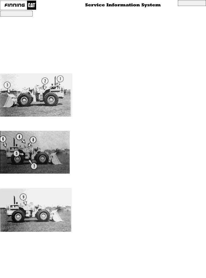
Engine (1), fuel tank (2) and bucket (3).
Operator's compartment (4), hydraulic tank (5), radiator (6), transmission (7), and battery (8).
Key disconnect switch (9).
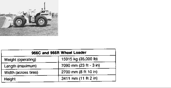
Basic machine shipping specifications are listed below.
Copyright 1993 - 2022 Caterpillar Inc. |
Mon Dec 19 2022 17:27:17 GMT+0700 (Indochina Time) |
|||
All Rights Reserved. |
||||
|
||||
Private Network For |
SIS Licensees. |
|
|
|

Shutdown SIS
Previous Screen
 Product: WHEEL LOADER
Model: 966C WHEEL LOADER 9KC
Configuration: 966C WHEEL LOADER / POWER SHIFT / 9KC00001-UP (MACHINE) POWERED BY 3306 ENGINE
Operation and Maintenance Manual
966C AND 966R WHEEL LOADERS
Media Number -SEBU6290-00 Publication Date -01/02/1990 Date Updated -11/10/2001
Product Identification and Serial Number Location
The Product Identification Number (PIN) will be used to identify a powered machine that is designed for an operator to ride.
Caterpillar products such as earthmoving equipment not designed for an operator to ride (engines, transmissions, etc.) are identified by Serial Numbers. Also, most major Caterpillar attachments are identified by Serial Numbers.
For quick reference, record the identification numbers in the spaces provided below the illustration photographs.
Machine PIN____________________
Service Information Number Plate (SIN)
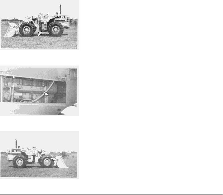
Transmission Serial Number____________________
Engine Serial Number____________________
Bucket Serial Number____________________
Copyright 1993 - 2022 Caterpillar Inc. |
Mon Dec 19 2022 17:27:27 GMT+0700 (Indochina Time) |
|||
All Rights Reserved. |
||||
|
||||
Private Network For |
SIS Licensees. |
|
|
|

Shutdown SIS
Previous Screen
 Product: WHEEL LOADER
Model: 966C WHEEL LOADER 9KC
Configuration: 966C WHEEL LOADER / POWER SHIFT / 9KC00001-UP (MACHINE) POWERED BY 3306 ENGINE
Operation and Maintenance Manual
966C AND 966R WHEEL LOADERS
Media Number -SEBU6290-00 Publication Date -01/02/1990 Date Updated -11/10/2001
Monitoring Systems and Cab Features
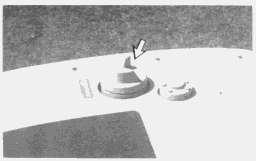
Battery Disconnect Switch
The battery disconnect switch is located on the right side of the operator's seat.
Disconnect Switch OFF (1) - Turn the key to the left to turn off the electrical system.
Disconnect Switch ON (2) - Insert the key, and turn it to the right, to turn on the electrical system. The switch must be on before starting the engine.
Remove the key when leaving the machine. Also, remove the key when servicing the electrical system.
NOTICE
Never turn the disconnect key off with the engine running. Engine damage could result.
Engine Heater and Start Switch
Preheat (1) - Turn the switch counterclockwise and hold to heat the engine glow plugs. The key returns to the
(2) position when released.
OFF (2) - The switch will return to the OFF position when released.
NOTE: Pull back on the accelerator pedal past the detent, to stop the engine.
ON (3) - Turn the switch clockwise and hold to start the engine. The key returns to the (2) position when released.
Gauges
Engine Oil Pressure (1) - Indicates the pressure of the engine oil. The GREEN RANGE is normal with the machine at high idle. The WHITE RANGE is normal with machine at low idle. The RED RANGE is low oil pressure. If the indicator is in the RED RANGE, stop the machine and investigate the cause.
Do not operate the machine until the cause has been corrected.
Engine Coolant Temperature (2) - Indicates the temperature of the engine coolant. The GREEN RANGE is normal operating temperature. The WHITE Range is cold coolant temperature. The RED RANGE is excessive coolant temperature. If the indicator is in the RED RANGE, stop the machine and investigate the cause.
Do not operate the machine until the cause has been corrected.
Ammeter (3) - Indicates the charging condition of the charging circuit. In normal operation, the indicator should be at zero. The GREEN RANGE indicates that the system is charging. The RED RANGE indicates that the system is discharging. If the indicator remains in the RED RANGE, stop the machine and investigate the cause.
Do not operate the machine until the cause has been corrected.
Torque Converter Oil Temperature (4) - Indicates the temperature of the torque converter oil. The GREEN RANGE is the normal operating temperature. The RED RANGE is excessive oil temperature. If the indicator is in the RED RANGE, stop the machine and investigate the cause.
Do not operate the machine until the cause has been corrected.
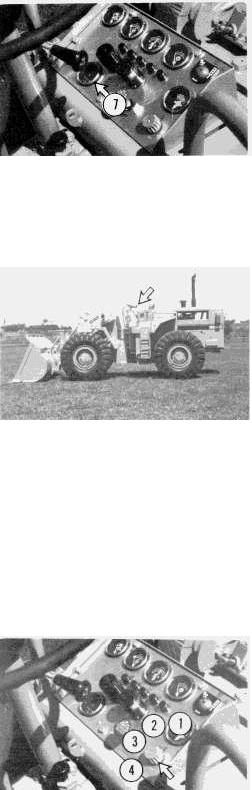
Air Pressure (5) - Indicates low brake system air pressure. The GREEN RANGE is the normal operating air pressure. The RED RANGE indicates low brake system air pressure. If the indicator is in the RED RANGE, stop the machine and investigate the cause.
Do not operate the machine until the cause has been corrected.
Air Pressure (6) - Indicates the brake system air pressure.
Service Hour Meter (7) - Indicates the total operating hours of the engine. It should be used to determine service intervals.
Supplemental Steering Light (If Equipped)
Supplemental Steering - Indicates the primary steering has failed and the supplemental steering is being used. If the indicator comes on during operation, the fault alarm should sound. Steer the machine immediately to a safe location and stop. Stop the engine and investigate the cause.
Do not operate the machine until the cause has been corrected.
Supplemental steering works only while the machine is moving. When the machine operates under supplemental steering, no directional changes can be made.
Light Switch
OFF (1) - Move the switch to this position to turn all lights off.
Panel Lights (2) - Move the switch clockwise to this position to turn the panel lights on.
Front Working Lights (3) - Move the switch clockwise, to this position, to turn on the front working lights.
All Lights (4) - Move the switch clockwise, to this position, to turn on all lights.
Horn
Horn - Push the knob down to sound the horn. Use the horn to alert or to signal personnel.
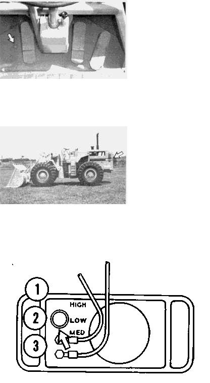
Back-up Alarm (If Equipped)
Back-up Alarm - The alarm will sound when the transmission control lever is in the reverse position. It is used to alert people behind the machine that it is backing up.
The back-up alarm is located on the rear of the machine.
A three position switch at the rear of the back-up alarm regulates its volume. (1) is High, (2) is Low and (3) is Medium.
The alarm is set at the highest sound level when shipped from the factory. The setting should remain on high, unless the job-site requires a lower level.
Seat Adjustment
NOTE: Adjust the seat at the beginning of each shift or when changing operators.
Adjust the seat to allow full travel of the pedals when the operator is seated against the seat back.
Push the lever to the operator's left, to allow moving the seat forward or backward.
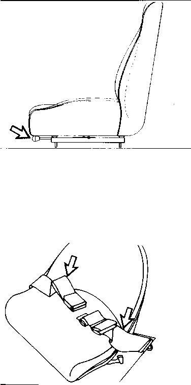
Seat Belt
Always check the condition of the seat belt and mounting hardware before operating the machine.
Replace the seat belt at least once every three years, regardless of appearance. A date label, to determine the age of the belt, is sewn onto each belt.
Inspect for worn or frayed webbing.
Check for worn or damaged buckle or anticreep slide on each half of the belt. Replace the belt, buckle or slides if they are worn or damaged.
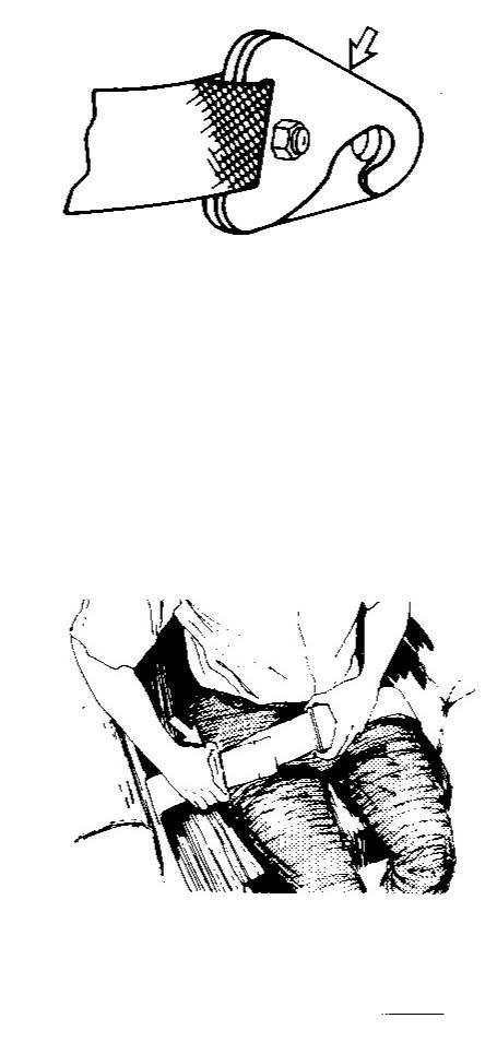
Inspect the belt mounting hardware. Replace any damaged or worn hardware. Keep the mounting bolts tight.
If the bolt and nut that holds the two parts of the seat belt mounting hooks together are not correctly installed, the hooks can separate. This will allow the seat belt to separate from its mounting.
Inspect the hooks of each half of the belt to make certain the bolt and nut are correctly installed.
If the bolt and nut are not correctly installed, remove them. Install a new bolt and nut.
Seat Belt Adjustment
Adjust both ends of the belt. The belt should be snug but comfortable.
To Lengthen the Belt
1. With the belt unfastened, move the anticreep slide toward the buckle.

2.To remove the slack in outer loop (1), rotate buckle (2) to free the lock bar. This permits the belt to move through the buckle.
3.Pull on the buckle until the slack is removed from the outer belt loop.
4.Loosen the other half of the belt in the same manner. Readjust the belt if it does not fit snugly with the buckle in the center.
To Shorten the Belt
1. With the belt fastened, pull on the outer loop to tighten the belt.
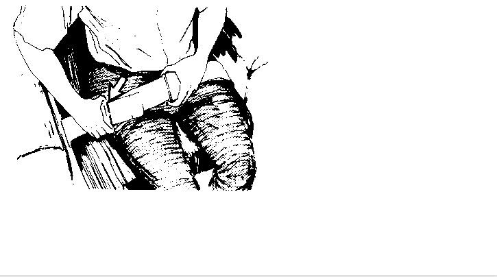
2.Move the anticreep slide toward the anchor end of the belt to take up the slack in the outer loop.
3.Adjust the other half of the belt in the same manner.
4.Readjust the belt if it does not fit snugly with the buckle in the center.
Copyright 1993 - 2022 Caterpillar Inc. |
Mon Dec 19 2022 17:27:42 GMT+0700 (Indochina Time) |
|||
All Rights Reserved. |
||||
|
||||
Private Network For |
SIS Licensees. |
|
|
|
Shutdown SIS
Previous Screen
 Product: WHEEL LOADER
Model: 966C WHEEL LOADER 9KC
Configuration: 966C WHEEL LOADER / POWER SHIFT / 9KC00001-UP (MACHINE) POWERED BY 3306 ENGINE
Operation and Maintenance Manual
966C AND 966R WHEEL LOADERS
Media Number -SEBU6290-00 Publication Date -01/02/1990 Date Updated -11/10/2001
Machine Controls
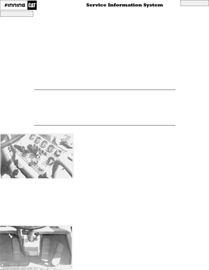
Parking/Secondary Brake
NOTICE
Do not engage the parking/secondary brake while the machine is moving unless an emergency exists. The use of the parking/secondary as a service brake in regular operation will cause severe damage to the parking/secondary brake system.
Parking/Secondary Brake - The parking/secondary brake is located on the dash.
Parking/Secondary Brake Engaged - Pull up on the knob to engage the parking/secondary brake.
Parking/Secondary Brake Disengaged - Push down on the knob to release the parking/secondary brake.
Brake Pedals

Left Brake Pedal - The left brake pedal disengages the transmission and brakes the machine. This permits higher engine speed for better hydraulic response.
Depress the left brake pedal when positioning and raising the bucket at the same time. Release the pedal to re-engage the transmission and to release the brake.
Right Brake Pedal - The right brake pedal slows down the machine ground speed for normal braking. Depress the right brake pedal for normal machine braking.
Release the pedal to release the brake.
Accelerator Pedal
Accelerator Pedal - The accelerator pedal is located on the floor of the operator's station, at the right. Push down the pedal to increase travel speed.
Release the pedal to decrease travel speed.
NOTE: Pull back on the accelerator pedal past the detent, to stop the engine.
Transmission Direction and Speed Control
Direction Selector
Forward (1) - Push the transmission lever forward. The machine will move forward.
Neutral (2) - The machine should not move when transmission lever is in neutral.
Reverse (3) - Pull the transmission lever toward the operator. The machine will move in reverse.
Speed Selector
Rotate the transmission lever to the desired gear speed: 1 - First Speed
2 - Second Speed
3 - Third Speed
4 - Fourth Speed
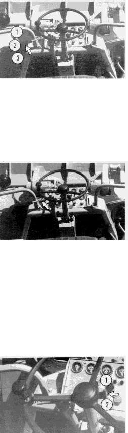
Transmission Neutral Lock
The transmission neutral lock is located on the right side of the steering column.
Unlocked (1) - Push down on the lever to release the transmission neutral lock.
Locked (2) - Pull up on the lever to lock the transmission neutral lock.
 Loading...