


 Loading...
CAT RP3600, RP5500, RP6500, RP6500 E, RP7500 E User Manual
...
501–6075-05
Owner's Manual
RP3600, RP5500, RP6500,
RP6500 E, RP7500 E and RP8000 E
Portable Generators
Important Safety Information
Most accidents that involve product operation, maintenance and repair are caused by failure to observe basic safety rules or precautions. An accident can often be avoided by recognizing potentially hazardous situations before an accident occurs. A person must be alert to potential hazards, including human factors that can affect safety. This person should also have the necessary training, skills, and tools to perform these functions properly.
Safety precautions and warnings are provided in this manual and on the product. If these hazard warnings are not heeded, bodily injury or death could occur to you or to other persons. The hazards are identified by the “Safety Alert Symbol”  and followed by a “Signal Word” such as “DANGER”, “WARNING” or “CAUTION”.
Caterpillar cannot anticipate every possible circumstance that might involve a potential hazard. The warnings in this publication and on the product are, therefore, not all inclusive. You must not use this product in any manner different from that considered by this manual without first satisfying yourself that you have considered all safety rules and precautions applicable to the operation of the product in the location of use, including site-specific rules and precautions applicable to the worksite. If a tool, procedure, work method or operating technique that is not specifically recommended by Caterpillar is used, you must satisfy yourself that it is safe for you and for others. You should also ensure that you are authorized to perform this work, and that the product will not be damaged or become unsafe by the operation, lubrication, maintenance, or repair procedures that you intend to use.
The information, specifications, and illustrations in this publication are on the basis of information that was available at the time that the publication was written. The specifications, torques, pressures, measurements, adjustments, illustrations, and other items can change at any time. These changes can affect the service that is given to the product. Obtain the complete and most current information before you start any job.
In the United States, the maintenance, replacement, or repair of the emission control devices and systems may be performed by any repair establishment or individual of the owner's choosing.
This manual contains safety, operation, and maintenance information. This manual should be stored near the product. Read, study and keep it with the literature and product information.
Consumer Arbitration Clause
The Limited Warranty included in this User Guide contains important legal terms including, but not limited to, a Consumer Arbitration Clause calling for mandatory individual arbitration and waiving the ability to bring a case as a class action. Please review this carefully.
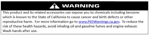
California Proposition 65 Warning
2
Table of Contents |
|
Consumer Arbitration Clause .................................................................................................................... |
2 |
CaliforniaProposition65 Warning............................................................................................................... |
2 |
SAFETY MESSAGES ................................................................................................................................... |
5 |
Additional Messages ................................................................................................................................. |
6 |
Battery (if equipped).................................................................................................................................. |
6 |
Special Requirements ............................................................................................................................... |
7 |
ASSEMBLY.................................................................................................................................................... |
8 |
Feet Assembly .......................................................................................................................................... |
8 |
Wheel Assembly ....................................................................................................................................... |
8 |
Battery Connection (If equipped) .............................................................................................................. |
8 |
Oil .............................................................................................................................................................. |
8 |
Carriage brackets ...................................................................................................................................... |
8 |
COMPONENT IDENTIFICATION.................................................................................................................. |
9 |
RP3600, RP5500, and RP6500 ................................................................................................................ |
9 |
RP6500 E, RP7500 E, and RP8000 E...................................................................................................... |
9 |
Engine Type & Serial Number ................................................................................................................. |
10 |
CONTROLS ................................................................................................................................................ |
11 |
Display..................................................................................................................................................... |
11 |
Generator Switch .................................................................................................................................... |
11 |
Choke ...................................................................................................................................................... |
11 |
CO DEFENSETM & Shut Off System (If equipped) |
................................................................................. 11 |
Fuel Switch.............................................................................................................................................. |
12 |
Recoil Starter........................................................................................................................................... |
12 |
AC Circuit Breaker .................................................................................................................................. |
12 |
CSA Circuit Breaker (If equipped)........................................................................................................... |
12 |
Low Oil Level Shutdown.......................................................................................................................... |
12 |
120 VAC, 20 Amp, Duplex ...................................................................................................................... |
12 |
RV Receptacle ........................................................................................................................................ |
13 |
120 VAC, 120/240 VAC 30 Amp, Locking .............................................................................................. |
13 |
GENERATOR OPERATION........................................................................................................................ |
13 |
Optimal Generator Operating Conditions................................................................................................ |
13 |
Connection to Household Power Supply ................................................................................................. |
13 |
Generator Grounding .............................................................................................................................. |
13 |
AC Usage ................................................................................................................................................ |
14 |
High Altitude Kits ..................................................................................................................................... |
14 |
BEFORE STARTING ENGINE ................................................................................................................... |
14 |
Engine Oil ................................................................................................................................................ |
14 |
Fuel ......................................................................................................................................................... |
14 |
Walk-Around Inspection .......................................................................................................................... |
14 |
STARTING THE ENGINE ........................................................................................................................... |
15 |
|
3 |
Recoil Start.............................................................................................................................................. |
15 |
Electric Start (If equipped)....................................................................................................................... |
15 |
STOPPING THE ENGINE........................................................................................................................... |
15 |
MAINTENANCE .......................................................................................................................................... |
15 |
Air Filter – Check..................................................................................................................................... |
15 |
Cylinder Head - Clean............................................................................................................................. |
16 |
Engine Oil Level – Check........................................................................................................................ |
16 |
Engine Oil – Change................................................................................................................................ |
16 |
Engine Valve Lash – Inspect/Adjust ....................................................................................................... |
17 |
Fuel Line – Replace ................................................................................................................................ |
17 |
Fuel Tank Cap and Strainer – Clean ...................................................................................................... |
17 |
Generator - Inspect ................................................................................................................................. |
17 |
Spark Arrestor - Inspect/Clean/Replace.................................................................................................. |
17 |
Spark Plug – Inspect/Adjust/Replace ...................................................................................................... |
17 |
Battery (if equipped)– Inspect/Replace .................................................................................................... |
18 |
Walk-Around Inspection .......................................................................................................................... |
18 |
STORAGE................................................................................................................................................... |
19 |
Storage for 1 to 3 months........................................................................................................................ |
19 |
Storage for more than 3 months ............................................................................................................. |
19 |
TROUBLESHOOTING ................................................................................................................................ |
20 |
SPECIFICATIONS ...................................................................................................................................... |
21 |
COMBINED EXHAUST AND EVAPORATIVE EMISSIONS CONTROLS WARRANTY STATEMENT...... |
22 |
Your Warranty Rights and Obligations.................................................................................................... |
22 |
Manufacturer’s Warranty Coverage ........................................................................................................ |
22 |
Owner’s Warranty Responsibilities ......................................................................................................... |
22 |
Defects Warranty Requirements: ............................................................................................................ |
22 |
WARRANTY................................................................................................................................................ |
24 |
CONSUMER ARBITRATION CLAUSE: MANDATORY BINDING INDIVIDUAL ARBITRATION |
|
INSTEAD OF COURT; CLASS ACTION WAIVER ................................................................................. |
24 |
4
SAFETY MESSAGES
There may be several specific safety messages on your generator. Please become familiar with all safety messages.
Ensure that all safety messages are legible. Clean the safety messages or replace the safety messages if the words cannot be read or if the illustrations are not visible. Use a cloth, water, and soap to clean the safety messages. Do not use solvents, gasoline, or other harsh chemicals. Solvents, gasoline, or harsh chemicals could loosen the adhesive that secures the safety messages.
Replace any safety message that is damaged or missing. If a safety message is attached to a part of the generator that is replaced, install a new safety message on the replacement part.
Read the Manual
Do not operate or work on this generator unless you have read and understand the instructions and warnings in the Owner’s Manual. Failure to follow the instructions or heed the warnings could result in injury or death. Proper care is your responsibility.
Hot Surface / Do Not Touch /
Flammable Material
Hot parts or hot components can cause burns or personal injury. Do not allow hot parts or components to contact your skin. Use protective clothing or protective equipment to protect your skin. Hot exhaust presents a potential fire hazard. Be sure that nothing flammable is within 1.5 meters of the exhaust.
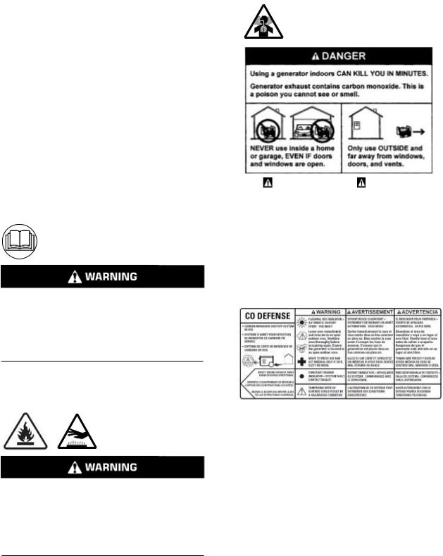
Carbon Monoxide
DANGER |
PELIGRO |
|
|
Utiliser un générateur à |
Si usa un generador en |
l’intérieur PEUT VOUS TUER EN |
interiores, MORIRA EN POCOS |
QUELQUES MINUTES. Les gaz |
MINUTOS. El escape del |
d’échappement du générateur |
generador contiene monóxido |
contiennent du monoxyde de |
de carbono. Es un veneno que |
carbone. C’est un gaz toxique |
no tiene olor ni se puede ver. |
invisible et inodore. |
NUNCA lo use dentro de una |
NE JAMAIS utiliser à l’intérieur |
casa o garaje. AUN si las |
d’une maison ou d’un garage, |
puertas y vantanas están |
MÊME SI les portes et les |
abiertas. |
fenêtres sont ouvertes. |
Sólo úselo en EXTERIORES |
Utiliser UNIQUEMENT à |
y lejos de ventanas, puertas y |
l’EXTÉRIEUR et loin des |
ductos de ventilación. |
fenêtres, portes et ventilations. |
|
|
|
Operating a generator indoors can kill you in minutes. Generator exhaust contains carbon monoxide. Carbon monoxide is a poison that you cannot see or smell. Never operate a generator inside a home or garage, even if doors and windows are open. Only operate a generator outdoors and away from windows, doors, and vents. Always direct engine exhaust away from occupied structures. If anyone experiences dizziness, headaches, nausea, or tiredness get to fresh air immediately and seek medical attention. Ventilate the area thoroughly before occupying again.
The carbon monoxide shutoff system is not a substitute for safe generator operation. Do Not adjust or modify the carbon monoxide shutoff system. Failure to follow instructions can cause the system to malfunction which can result in hazardous conditions.
5
Battery (if equipped)
Electrocution
CAUTION
Shock/Electrocution Hazard: Do not operate this equipment or work on this equipment unless you have read and understand the instructions and warnings in the Owner’s Manual. Failure to follow the instructions or heed the warnings will result in serious injury or death.
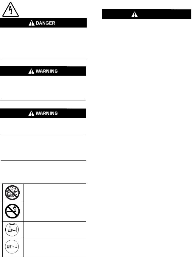
Operation of this equipment may create sparks that can start fires around dry vegetation. A spark arrestor may be required. The operator should contact local fire agencies for laws or regulations relating to fire prevention requirements.
Electrical backfeed into a utility’s distribution system can cause property damage, severe injury, or death.
Electrical backfeed warning. Do not connect generator to a building’s electrical system unless using an isolation (transfer) switch installed by a certified, licensed electrician. CA H&S Code 119075 & 119080.
.
Additional Messages
Do not operate in wet conditions.
Do not refuel near open flames. Do not refuel while the engine is running. Do not smoke while refueling.
Maintain a minimum distance of 5 feet (1.5 meters) from other objects.
Ensure that the unit is properly grounded.
1.Do not expose battery to temperatures above 60 C (140 F).
2.Do not reverse the positive (+) or negative (-) terminals or short-circuit the battery in any way.
3.Do not allow charge voltages in excess of 40 volts.
4.If the battery becomes hot to the touch, stop charging. Allow battery to cool before charging.
5.Do not open, disassemble or modify the battery in any way.
6.Do not connect the battery to other batteries in any way.
7.Do not over-discharge the battery. It may damage the battery or shorten the battery life.
8.A flammable hazard may exist if the battery is physically damaged.
9.Failure to follow these instructions may present risk of explosions, fire or high temperatures.
6
Special Requirements
Electrical equipment, including lines and plug connections shall be covered and protected from moisture.
The circuit breakers shall match the generator specifications. If the circuit breakers require replacement, they must be replaced with a circuit breaker of the same rating and performance characteristics. In any generator set installation, the frame of the generator must be connected to an earth ground. A ground terminal is provided.
RP5500, RP6500, RP6500 E, RP7500 E, and RP8000 E all have a permanent neutral conductor between the stator winding and the frame. RP3600 has a floating neutral.
For 120VAC duplex receptacles, use extension cords rated for 125V at 20A or greater, and 30A or greater for locking receptacles. For 240VAC use extension cords rated for 250V at 30A or greater. Use the shortest extension cord that meets these requirements.
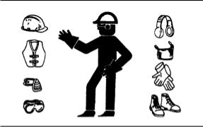
•Wear a hard hat, protective glasses, and other protective equipment, as required.
•When work is performed around an engine that is operating, wear protective devices for ears in order to help prevent damage to hearing.
•Do not wear loose clothing or jewelry that can snag on controls or on other parts of the engine.
•Ensure that all protective guards and all covers are secured in place on the engine.
•Never put maintenance fluids into glass containers. Glass containers can break.
•Use all cleaning solutions with care.
7
ASSEMBLY
7 |
6 |
8 |
|
1
 6 5
6 5
2 |
4 |
|
2 |
3 |
3 |
|
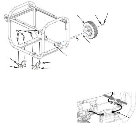
Feet Assembly
1.Set the frame of the unit on blocks to provide sufficient clearance to install the feet and wheels.
2.Align the mounting holes of the foot bracket (2) with the mounting holes in the frame.
3.Insert one 8 mm bolt (1) through each set of mounting holes.
4.Install and hand tighten one 8 mm nut
(3) on each bolt.
5.Repeat steps 2 – 4 for the other foot.
6.Tighten all four nuts securely.
Wheel Assembly
1.Insert short end of axle (5) into the mounting bracket on the frame.
2.Install one 10 mm nut (4) on the axle and tighten securely to frame.
3.Place one large washer (6) on the long end of the axle and install wheel (7) with the bolt design facing out.
4.Install one large washer (6) onto the axle.
5.Install one 10 mm locking nut (8) onto the axle and tighten securely.
6.Repeat steps 1 – 5 for the other wheel.
7.Remove the blocking.
Battery Connection (If equipped)

 2
2
RP6500 E, RP7500 E, and RP8000 E come with the battery mounted in the battery holder. To connect the battery:
1.The unit ships with the positive battery cable (1) already connected.
2.Attach the cable with the black cap (2) to the other cable with the connector.
Oil
Follow the Engine Oil Level-Check procedure to add the proper amount of oil for the unit as described in the Specifications chart.
Carriage brackets
The generator has 2 red carriage brackets fitted underneath the base to prevent damage caused by rough handling during transit.
IMPORTANT- These be must be removed before use, otherwise the unit will vibrate excessively and damage may occur.
8
COMPONENT IDENTIFICATION
RP3600, RP5500, and RP6500
2 |
3 |
4 |
|
|
|
5 |
|
||
|
|
|
||
|
|
|
6 |
|
1 |
|
|
|
|
|
|
|
|
|
|
|
|
|
7 |
|
|
|
|
8 |
18, 19 |
|
|
|
|
|
|
|
|
9 |
17 |
|
|
|
10 |
16 |
|
|
|
|
|
|
|
|
11 |
|
14 |
|
12, 13 |
|
|
15 |
|
|
|
RP6500 E, RP7500 E, and RP8000 E
2 |
3 |
4 |
|
|
|
5 |
|
||
|
|
|
||
|
|
|
6 |
|
1 |
|
|
|
|
|
|
|
|
|
|
|
|
|
25 |
|
|
|
|
8 |
18, 19 |
|
|
|
|
|
|
|
|
9 |
17 |
|
|
|
10 |
|
|
|
|
|
16 |
|
|
|
|
|
|
|
|
11 |
|
14 |
|
12, 13 |
|
|
15 |
|
|
|
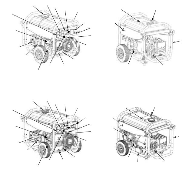
1)Receptacle – 120 VAC double
2)Fuel Cap
3)Circuit Breaker
4)CO Detector (If equipped)
5)Display
6)Generator Switch
7)Receptacle – 30A 120 VAC RV* Receptacle – 120/ 240 VAC locking+
8)Panel Light
9)Fuel Valve
10)Recoil Start
11)Oil Drain
12)Air Filter Assembly
13)Air Filter
14)Choke Knob
*RP3600
+RP5500
9
20 |
21 |
4
22
24 |
23 |
20 |
21 |
|
4
27
22
24 |
|
23 |
|
26 |
|
|
|
15)CARB Canister (If equipped)
16)Spark Arrestor
17)Muffler
18)Engine
19)Spark Plug
20)Fuel Gauge
21)Fuel Tank Vent Pipe
22)Handle Assembly
23)Alternator
24)Oil Gauge / Oil Fill
25)Receptacles – 120/240 VAC locking & 120 VAC locking
26)Battery
27)Starter
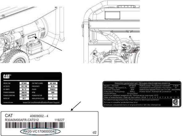
Engine Type & Serial Number
1 
2
 1
1
3 
2
Cat® portable generators are identified with model numbers, serial numbers, and with performance specification numbers. The model number and performance specifications are located on the ratings plate (1) or the CSA ratings plate (3). The serial number is located on the serial number plate (2).
10
CONTROLS |
CO DEFENSETM & Shut Off System (If |
|
equipped) |
Display |
|
This generator is equipped with a display that can show the voltage, frequency, total accumulated hours of operation, and current hours. Use the toggle switch (1) to change the readout of the display to the desired setting.
The display will show 3 maintenance messages when running: P-25 displays after the first 25 hours running to remind the user to change engine oil. P- 50 displays after every 50 hours of use to remind user to change engine oil and check spark arrestor. P-100 displays after every 100 hours of use to remind user to change engine oil and check spark plug. These codes fade away after 6 minutes of use.
Generator Switch
Generator Switch |
Generator Switch |
(Pull Start) |
(Electric Start) |
For pull starting the generator, turn the generator switch to the on position “I” before starting the generator. For models with electric starting, turn the generator switch to the start position “  ”. To turn off the generator, turn the generator switch to the off
“0” position.
Choke
The choke is used to provide more fuel when starting a cold engine. If the engine is cold, pull the choke knob out before starting the engine. Once the engine starts, slowly push in the choke knob.
The (carbon monoxide) CO DEFENSE system monitors the accumulation of carbon monoxide gas while the generator is running and will shut off the engine if the levels become dangerously high. The CO DEFENSETM on this generator is not a substitute for an indoor CO alarm.
Whenever the CO DEFENSE has shut off the engine there will be a light on the control panel that indicates the reason. Read the CO Action Label (shown above) for the next steps to take.
If the CO DEFENSE light is flashing “red” you must leave the area immediately and relocate to an open outdoor area. Ventilate the area thoroughly before again occupying it. Ensure the generator is located in an open outdoor area with the exhaust pointed away from occupied structures. If anyone experiences dizziness, headaches, nausea, or fatigue get to fresh air immediately and seek medical attention.
If the CO DEFENSE light is a constant “orange” then a system fault has occurred, or it is indicating that it has reached the end of its life. This fault can only be diagnosed and repaired by an Authorized Service Provider.
The CO DEFENSE monitors the accumulation of CO gas from all sources in the area around the generator. If the CO DEFENSE light is flashing “red” this is not an error and safety measures must be taken immediately.
Note: Tampering with the CO DEFENSE could result in hazardous conditions and must be avoided.
Note The generator must not be operated in ambient temperatures greater than 131oF (55oC) as this can damage the CO DEFENSE.
11
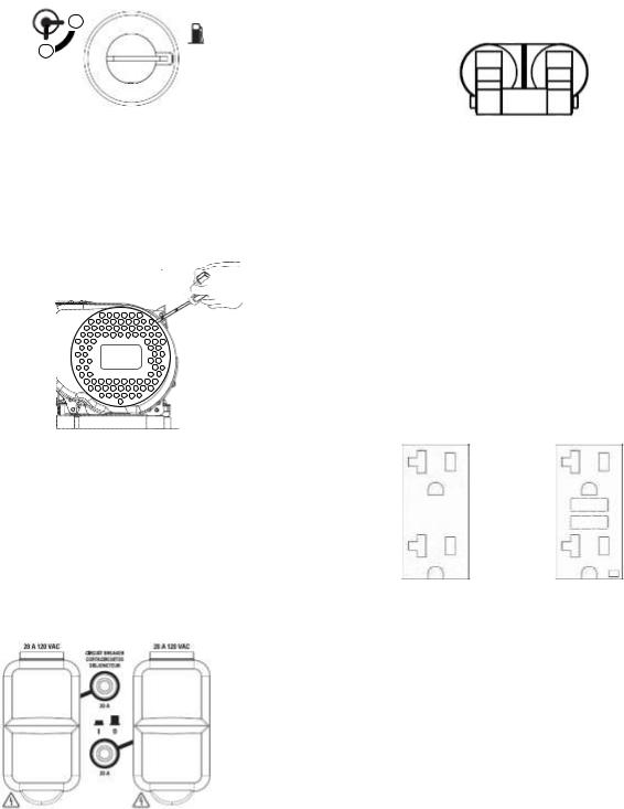
Fuel Switch
I
O
The fuel switch controls the flow of the fuel from the fuel tank to the carburetor. Turn the fuel switch to the on “I” position before starting the engine. Turn the fuel switch to the off "O" position after stopping the engine.
CSA Circuit Breaker (If equipped)
On
Off
240V portable generators sold in Canada come with an additional circuit breaker that will isolate all outlets on the panel. This breaker must be in the “On” position for the unit to provide power.
Recoil Starter |
Low Oil Level Shutdown |
|
|
|
The generator is equipped with a low oil level |
|
shutdown that is designed to protect the engine from |
|
damage caused by an insufficient amount of oil in |
|
the crankcase. When the oil level in the crankcase |
|
falls below the safe operating limit, the low oil level |
|
shutdown will automatically shut off the engine. |
|
120 VAC, 20 Amp, Duplex |
To start the engine, slowly pull the starter handle until resistance is felt, then quickly pull the starter handle the rest of the way.
Do not allow the starter handle to snap back against the engine. Return it gently to prevent damage to the starter.
AC Circuit Breaker
The generator comes equipped with circuit breakers that protect the unit and the load from short circuit or overload conditions. If the circuit breaker opens, determine why the circuit breaker tripped before closing the circuit breaker.
The 120 VAC duplex receptacle is protected against overload by a 20 Amp push to reset circuit breaker. It also provides protection via a Ground Fault Circuit Interruptor (GFCI) with press to Test and Reset buttons (RP5500, RP6500, RP6500 E, RP7500 E, RP8000 E). Use the receptacle to power a NEMA 5- 20, 120 VAC, single phase, 60 Hz electrical load requiring 20 Amps of current.
Use only high quality, well insulated, 3-wire grounded cords rated for 125 V at 20 Amps (or greater). Keep extension cords as short as possible (less than 15 feet) to prevent voltage drop and overheating of wires.
12
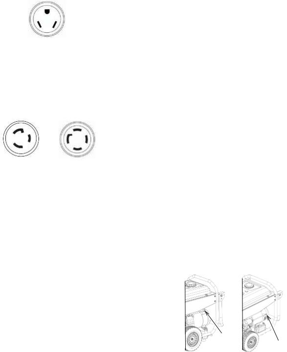
RV Receptacle
The 120 VAC RV outlet is protected against overload by a 30 Amp push to reset circit breaker. Use a NEMA TT-30 (120 VAC outlets) plug with this receptacle.
Use the receptacle to power a 120 VAC, single phase, 60 Hz electrical load.
120 VAC, 120/240 VAC 30 Amp, Locking
The 120 VAC and 120/240 VAC locking receptacles are protected against overload by the following push to reset circuit breakers:
|
Individual |
Main |
|
Breaker |
|
|
Breaker |
|
|
|
|
RP5500 |
|
23 A |
RP6500 |
|
28 A |
RP6500 E |
|
28 A |
RP6500 E CSA |
|
27 A * |
RP7500 E |
30 A |
31 A |
RP7500 E CSA |
|
30 A * |
RP8000 E |
30 A |
33 A |
*Double pole
Use a NEMA L5-30 (120 VAC outlets) or NEMA L1430 (120/240 VAC outlets) plug with this receptacle (rotate to lock or unlock).
Use the receptacles to supply a single phase 60 Hz 120 V AC or 240 VAC electrical load.
GENERATOR OPERATION
Optimal Generator Operating Conditions
•Temperature: 23oF to 104 oF (-5oC to 40oC)
•Humidity below 95%
•Height above sea level: < 3000 feet (900 m). If the height of the operating area is over 900 m high, output power will be reduced.
Standard operating conditions are 77oF (25oC) and 40% humidity. Generator power may be reduced due to different ambient conditions and other factors such as fuel quality.
Connection to Household Power Supply
This generator must be installed in accordance with all applicable local laws and electrical codes. The generator must be isolated from the utility and the connection must be verified by a qualified electrician.
Generator Grounding
The National Electrical Code requires generators to be grounded to an approved earth ground. Correct grounding for the generator is necessary for optimum engine performance and reduces the risk of electric shock. Use the ground terminal to properly ground the generator. Before using the ground terminal, consult a qualified electrician, electrical inspector, or local authority having jurisdiction for local codes or ordinances that apply for the intended use of the generator.
1
2
1.RP3600 Earth Ground
2.RP5500, RP6500, RP6500 E, RP7500 E, RP8000 E Earth Ground
13
AC Usage
Do NOT overload the generator. Exceeding the rated power of the generator can damage the generator and the electrical devices connected to it.
Motor-driven devices require a large starting current. Make sure that the total power requirement of these types of loads does not exceed the rated power of the generator.
When the generator is used to power multiple loads or electric appliances, start by connecting the appliance with the highest starting power requirements, followed by the second highest and ending with the lowest.
High Altitude Kits
At higher altitudes, the standard fuel to air mixture is too rich and will cause decreased performance and increased fuel consumption. A rich mixture will also foul the spark plug and make starting difficult. Operation at higher altitudes for extended periods of time may increase emissions.
Proper operation can be ensured by installing an altitude kit when required. High altitude kits should be installed by a qualified technician. Contact an authorized service provider if the portable generator will be operated at altitudes greater than 3000 feet (0.9 km) above sea level.
Note: At elevations greater than 8000 feet above sea level, the engine may experience decreased performance even with the high-altitude kit installed.
BEFORE STARTING ENGINE
Engine Oil
Check the oil level before each use. Refer to the Engine Oil - Check procedure in this manual.
Fuel
1 3
2 |
4 |
|
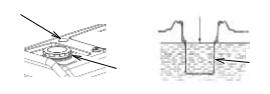
1.Check the fuel level gauge (1).
2.If the fuel level is low, remove fuel cap (2)
3.Check the strainer. If the strainer is dirty, clean the strainer. Refer to Fuel Tank Cap and Strainer – Clean for instructions.
4.Add fuel. The use of a fuel stabilizer is highly recommended as the unit may sit for long periods of time before needed.
5.Install the fuel cap after fueling.
To avoid personal injury always use caution when you are adding fuel:
•Fuel the generator in a well-ventilated area.
•Always stop the engine before fueling.
•Allow the engine to cool before fueling.
•Do not smoke while you are fueling the generator.
•Do not fuel the generator near open flames or sparks.
•Do not fill the fuel tank above the full line (3).
•Avoid repeated or prolonged contact with skin
•Avoid prolonged breathing of fuel vapor.
To avoid damaging the generator:
•Use unleaded gasoline with an octane rating greater than 86.
•Do not mix oil with the gasoline.
•Do not use gasoline with greater than 10% ethanol content.
•Do not use old gasoline.
•Avoid getting dirt or water into the fuel tank.
Walk-Around Inspection
Perform the Walk-Around Inspection before each use as described later in this manual.
14
STARTING THE ENGINE
Recoil Start
1.Isolate the generator from the utility
2.Unplug any electrical devices from the receptacles.
3.Turn the fuel switch to the on "I" position.
4.Turn the AC circuit breakers to the off “0” position (CSA models only).
5.If the engine is cold, pull out the choke knob.
6.Turn the generator switch to the on "I" position.
7.Slowly pull the starter handle until resistance is felt, then quickly pull the starter handle the rest of the way. If the engine does not start, repeat step 7 until the engine does start.
8.After the engine has warmed, push in the choke knob.
9.Turn the AC circuit breaker to the on "I" position.
Electric Start (If equipped)
1.Isolate the generator from the utility.
2.Unplug any electrical devices from the receptacles.
3.Turn the fuel switch to the on “I” position.
4. Turn the AC circuit breakers to the off “0” position (CSA models only).
5.If the engine is cold, pull out the choke knob.
6.Turn the generator switch to the start position “  ” and hold it there until the engine starts.
NOTE: Do not hold the generator switch in the start position “  ” for more than 5 seconds. Holding the generator switch in the start position “
  ” for more than 5 seconds will damage the starter. If the engine fails to start, wait 10 seconds before trying again.
7.After starting the engine, immediately release the generator switch so the switch can automatically return to the on “I” position.
8.After the engine has warmed, push the choke knob in.
9.Turn the AC circuit breaker to the on "I" position.
STOPPING THE ENGINE
1.Disconnect the generator / unplug all electrical devices.
2.Turn the AC circuit breaker to the off “0” position (CSA models only).
3.Turn the generator switch to the off “0” position.
4.Turn the fuel switch to the off “0” position.
Note: To stop the engine in an emergency, turn the generator switch to the off “0” position.
MAINTENANCE
Ensure that all safety information, warnings, and instructions are read and understood before any maintenance procedures are performed.
Use service hours or calendar time, WHICH EVER OCCURS FIRST, to determine the correct maintenance intervals.
Stop the engine before servicing. Put the engine in horizontal position and remove the spark plug cap to prevent the engine from starting. Do not operate the engine in an unventilated room or other enclosed area.
When Required:
Fuel Tank Cap and Strainer – Clean
Every Use:
Engine Oil Level – Check
Walk-Around Inspection
First 25 Service Hours or 1 Month:
Engine Oil – Change
Every Month:
Generator – Inspect
Every 50 Service Hours or 3 Months:
Air Filter – Check
Spark Arrester – Inspect/Clean/Replace
Every 100 Service Hours or 6 Months:
Engine Oil – Change
Spark Plug – Inspect/Adjust/Replace
Every 300 Service Hours or 1 Year:
Carbon Brush – Inspect/Repair/Replace
Cylinder Head – Clean
Engine Valve Lash – Check
Every 2 Years:
Fuel Line – Replace
NOTE: Use only genuine Caterpillar parts.
Air Filter – Check
A dirty air filter will restrict air flow into the carburetor, will cause poor fuel economy, and may damage the engine. To keep the generator in good operating condition, service the air filter regularly. Service more frequently when operating the generator in extremely dusty areas.
Note: Never operate the generator without the air filter in place. Operating the generator without the air filter in place will result in rapid engine wear.
15
1
3
2
Remove the air filter cover bolt (3) and remove the air filter cover (2). Make sure that the air filter (1) is clean and not damaged. If the air filter is dirty, wash the filter. If the air filter is damaged, replace the air filter.
Use a nonflammable solvent or a mixture of household detergent and warm water to wash the filter. Rinse the filter thoroughly to remove all of the cleaning solution. After the filter has dried, pour some engine oil onto the filter. Then squeeze the filter to distribute the oil throughout the filter and remove any excess oil.
Note: Do not wring out the filter. Wringing out the filter may damage the filter.
Install the filter into the filter housing. Place the air filter cover over the filter and reinstall the air filter cover bolt.
Cylinder Head - Clean
Only qualified service personnel should perform this maintenance procedure. Contact your local service center to schedule this maintenance.
Engine Oil Level – Check
Always check the engine oil with the generator on a level surface and with the engine stopped.
1 
 2
2
4 
5 
3
2.Check the oil level by inserting the oil level gauge into the filler neck. Do not screw the oil filler cap in when checking the oil level.
3.If the oil level is low (5), add the recommended engine oil until the oil level reaches the upper mark (4) on the oil level gauge. Use the chart below to determine which viscosity oil to use.
Recommended Lubricant Viscosities for
Ambient Temperature
Oil |
|
oC |
|
oF |
||
|
|
|
|
|
|
|
Viscosities |
Min |
|
Max |
Min |
|
Max |
|
|
|
||||
|
|
|
|
|
|
|
SAE 0W-40 |
-40 |
|
40 |
-40 |
|
104 |
|
|
|
|
|
|
|
SAE 5W-40 |
-30 |
|
50 |
-22 |
|
122 |
|
|
|
|
|
|
|
SAE 10W-30 |
-18 |
|
40 |
0 |
|
104 |
|
|
|
|
|
|
|
SAE 15W-40 |
-10 |
|
50 |
14 |
|
122 |
|
|
|
|
|
|
|
4.After adding oil, install and tighten the oil filler cap.
Note: Non-detergent and 2-stroke engine oils will damage the engine and must not be used.
Engine Oil – Change
1 
 2
2
4 
5 
3
1.Operate the engine until it reaches normal operating temperature. Stop the engine and use a suitable container to collect the used oil.
2.Remove the oil filler cap (1) and drain plug
(3) to drain the oil.
3.Reinstall the drain plug and tighten to 18 ± 2 lb ft (24 ± 3Nm).
4.Refill the oil and check the oil level. Refer to Engine Oil Level – Check.
5.Install and tighten the oil filler cap.
6.Dispose of the used oil properly.
1.Remove the oil filler cap (1) and wipe the oil level gauge (2) to clean it.
16
Engine Valve Lash – Inspect/Adjust
Only qualified service personnel should perform this maintenance procedure. Contact your local service center to schedule this maintenance.
Fuel Line – Replace
Only qualified service personnel should perform this maintenance procedure. Contact your local service center to schedule this maintenance.
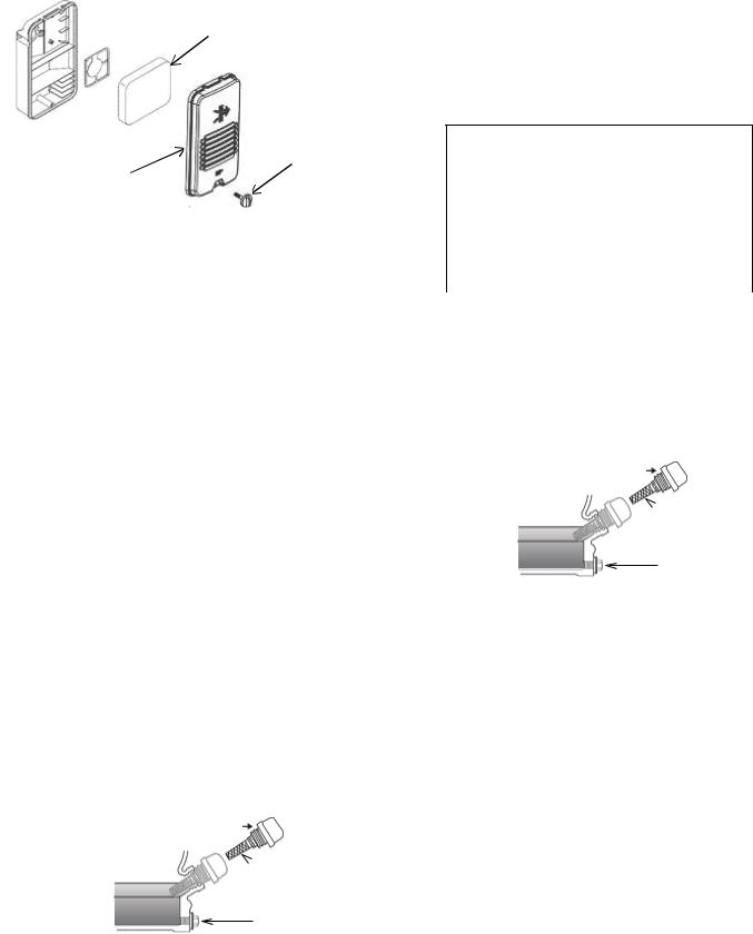
Fuel Tank Cap and Strainer – Clean
1 
2
Wipe off the fuel cap (1) and surrounding area before removing the fuel cap. Wiping off the fuel cap and surrounding area before removing the fuel cap helps to reduce the amount of contaminants allowed into the fuel system.
If there is a build-up of debris in the fuel strainer (2), remove the strainer and rinse out the strainer. Allow the strainer to dry before installing the strainer.
Generator - Inspect
Once a month start the engine and run the engine until it reaches normal operating temperature (about 20 minutes). Plug in a corded device and turn on the device to ensure that the generator is providing power. Once you have verified that the generator is providing power, turn off the device and unplug it. Then turn the generator off.
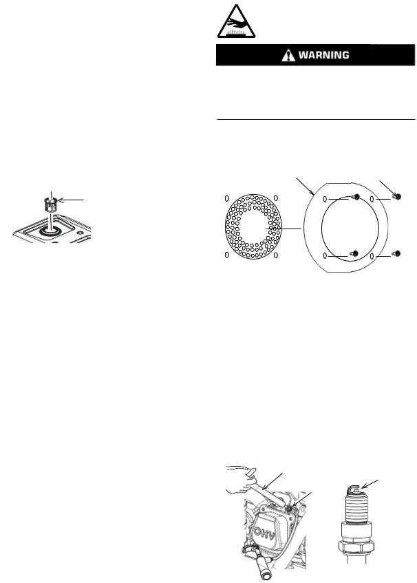
Spark Arrestor -
Inspect/Clean/Replace
This unit has a spark arrestor fitted to the exhaust outlet of the muffler. The spark arrestor should be cleaned with a soft wire brush after every 50 hours or 3 months of use. The spark arrestor should be replaced after every 100 hours of operation or if it becomes damaged.
Hot Surface
Hot parts or hot components can cause burns or personal injury. Do not allow hot parts or components to contact your skin. Use protective clothing or protective equipment to protect your skin.
DO NOT perform this maintenance procedure until the muffler has cooled.
1 |
|
2 |
||
|
|
|
|
|
|
|
|
|
|
|
|
|
|
|
|
|
|
|
|
|
|
|
|
|
|
|
|
|
|
Remove screws (2). Remove spark arrestor (1) Check the spark arrestor. Carefully clean the spark arrestor with a soft wire brush. If the spark arrestor is damaged, replace the spark arrestor.
To install the spark arrestor, align the mounting holes in the spark arrestor with the mounting holes on the muffler. Insert screws (2) and tighten securely.
Spark Plug – Inspect/Adjust/Replace
Refer to the Specifications section of this manual to determine the proper spark plug part number and spark plug gap for your product.
1
4
2
3
1.Remove the side panel.
2.Remove the spark plug cap (3).
3.Use the plug wrench (1) to remove the spark plug.
17
4.Visually check the spark plug to see if it is damaged. If the insulator is cracked, replace the spark plug. If the electrode is damaged, replace the spark plug.
5.Measure the plug gap (4) with a feeler gauge. Adjust the gap as necessary by carefully bending the side electrode. Refer to Specifications for the correct gap for your product.
6.Check the spark plug washer to ensure proper working condition. If the washer is damaged, replace the washer.
7.Install spark plug and tighten to 16 ± 2 lb ft (22 ± 2 Nm). DO NOT overtighten as this may damage the engine.
Battery (if equipped)– Inspect/Replace
If the battery voltage is below 12.8 volts, charge the battery. Recommended maximum continuous charge voltage is 15 volts.
If the battery is unable to turn over the engine, even after charging, check the battery terminals are secure and free from corrosion.
If the battery requires replacement:
1.Disconnect the negative (-) cable first.
2.Disconnect the positive (+) cable second.
To install the new battery:
1.Connect the positive (+) cable first.
2.Connect the negative (-) cable second.
NOTE: Use only genuine Caterpillar parts.
CAUTION - DANGER OF EXPLOSION IF BATTERY IS INCORRECTLY REPLACED, REPLACE ONLY WITH THE SAME OR EQUIVALENT TYPE.
The used battery should be recycled in accordance with local laws.
Walk-Around Inspection
Before starting the engine perform a visual inspection of the unit. Look for:
•Proper oil level
•Proper fuel level
•Good quality fuel
•Fluid leaks
•Loose clamps
•Loose bolts
•Cracked fuel line
•Loose or frayed wiring
•Built up debris
In addition, make sure that:
•The ground terminal is properly connected
•The circuit breakers are in OFF “ 0 ” position
18
STORAGE
When a generator is in storage, air may condense and moisture may appear on the windings. In order to minimize condensation, always store the generator in a dry area. Cover the generator with a protective cover that extends to the ground. The cover should remain loose around the generator in order to allow proper ventilation.
The generator must not be stored in ambient temperatures greater than 131oF (55oC) as this can damage the CO Detector (if equipped).
Storage for 1 to 3 months
Remove any dirt, rust, grease, and oil from the generator. DO NOT use a pressure washer to clean the generator. Inspect the exterior. Make any necessary repairs.
Add fuel stabilizer to the fuel tank to prevent the gasoline from going bad. Start and run the engine for 10 minutes to ensure that the fuel stabilizer has been pulled in to the carburetor. Shut off the engine and allow the engine to cool.
Turn the fuel valve to the off “O“ position.
Move the generator to the storage place. Cover the generator.
Storage for more than 3 months
Remove any dirt, rust, grease, and oil from the generator. DO NOT use a pressure washer to clean the generator. Inspect the exterior. Make any necessary repairs.
1
Gasoline is extremely flammable and is explosive under certain conditions. Drain the fuel in a wellventilated area with the engine stopped and cool. Never smoke or allow flames or sparks in the area during this procedure.
Make sure that the fuel valve is in the on “I“ position. Remove the fuel cap and the drain plug
(1) from the carburetor bowl and drain the fuel into a suitable container. DO NOT save the fuel for future use in the generator. Once the fuel has completely drained from the system install the drain plug into the carburetor. Turn the fuel valve to the off “O“ position. Apply a small amount of oil to the threads on the fuel tank filler neck and install the cap.
Change the engine oil.
Remove the spark plug and pour a small amount of oil into the cylinder. Install the spark plug but do not install the spark plug cap. Pull the starter handle 3 times to distribute the oil over the cylinder walls.
Remove the battery and place the battery in storage. Periodically check the battery and charge the battery when needed.
Move the generator to the storage place. Cover the generator.
19

TROUBLESHOOTING
Issue: |
Possible Cause: |
Solution: |
Check: |
|
|
Generator switch in the off “ 0 ” |
Turn the generator switch to the |
|
|
|
position |
correct position. |
|
|
|
|
|
|
|
|
Choke knob in the wrong position |
Place the choke knob in the |
|
|
|
correct position. |
|
||
|
|
|
||
|
|
|
|
|
|
No fuel |
Fill the fuel tank. |
|
|
|
|
|
|
|
|
Bad or contaminated fuel |
Check the fuel. |
|
|
|
|
|
|
|
|
Not enough oil in the engine |
Check the oil level. If low, add |
|
|
|
the recommended oil. |
|
||
|
|
Start the engine. |
||
Engine Will |
|
|
||
Dirty air filter |
Clean the air filter. |
|||
|
||||
Not Start |
|
|||
|
|
|
||
No fuel at the carburetor |
Make sure the fuel switch is in |
|
||
|
|
|||
|
the on "I" position. |
|
||
|
|
|
||
|
|
|
|
|
|
Engine flooded |
Wait 5 minutes. |
|
|
|
|
|
|
|
|
No spark |
Replace the spark plug. |
|
|
|
|
|
|
|
|
For electric start, start the engine |
If the generator starts, check the |
|
|
|
battery. If the battery is providing |
|
||
|
using the recoil starter. |
|
||
|
less than 12.4 volts, replace. |
|
||
|
|
|
||
|
|
|
|
|
|
If the engine still will not start: |
Take the unit to an authorized service provider. |
||
|
|
|
|
|
|
Dirty air filter |
Stop the engine and check the |
|
|
|
air filter. Clean if needed. |
Start the engine / |
||
Engine Runs |
|
|||
|
|
|||
|
Place the choke knob in the |
check if it runs rough. |
||
Rough (no |
Choke knob in the wrong position |
|||
|
||||
load) |
correct position. |
|
||
|
|
|||
|
|
|
|
|
|
If the engine still runs rough: |
Take the unit to an authorized service provider. |
||
|
|
|
|
|
|
Out of fuel |
Check the fuel. Fill the tank if |
|
|
|
necessary. |
|
||
|
|
|
||
|
|
|
|
|
|
Not enough oil in the engine |
Check the oil level. If low, add |
|
|
|
the recommended oil. |
|
||
|
|
Start the engine / |
||
|
|
|
||
|
Dirty air filter |
Clean the air filter. |
||
|
check if it shuts down. |
|||
|
|
|
|
|
Engine Shuts |
Generator overloaded |
Unplug some of the devices. |
|
|
Down |
|
|
|
|
Shut off due to CO accumulation |
Follow all safety instructions on |
|
||
|
|
|||
|
& flashing red indicator |
CO Action Label |
|
|
|
|
|
|
|
|
Shut off due to CO detector |
|
|
|
|
system fault & constant orange |
System fault or end of life indication. Take the unit to an |
||
|
indicator |
|||
|
authorized service provider. |
|||
|
|
|||
|
If the engine still shuts down: |
|
|
|
|
|
|
|
|
|
|
|
|
|
|
Dirty air filter |
Stop the engine and check the |
|
|
|
air filter. Clean if needed. |
|
||
|
|
Start the engine / |
||
Engine Runs |
|
|
||
Generator overloaded |
Unplug some of the devices. |
|||
check if it runs rough. |
||||
Rough (with |
||||
|
|
|
||
load) |
Defective device plugged in |
Unplug defective device. |
|
|
|
|
|
|
|
|
If the engine still runs rough: |
Take the unit to an authorized service provider. |
||
|
|
|
|
|
|
Circuit breaker is open |
Close the circuit breaker. |
|
|
|
|
|
|
|
Engine Runs, |
Bad connection |
Stop the engine and check the |
Start the engine / |
|
But Generator |
connections. |
|||
|
||||
|
check for power. |
|||
Does Not |
|
|
||
Defective power cord |
Replace the cord. |
|||
|
||||
Provide |
|
|||
|
|
|
||
Defective device plugged in |
Unplug defective device. |
|
||
Power |
|
|||
|
|
|
|
|
|
If there is still no power: |
Take the unit to an authorized service provider. |
||
|
|
|
|
|
20
SPECIFICATIONS
|
RP3600 |
RP5500 |
|
RP6500 |
|
RP6500 E |
|
RP7500 E |
|
RP8000 E |
|
|
|
|
|
|
|
|
|
|
|
Engine Type |
Single Cylinder, 4-Stroke, Forced Air Cooling, OHV |
|
|
|||||||
|
|
|
|
|
|
|
|
|||
Displacement (cc) |
212 |
301 |
|
420 |
|
420 |
|
420 |
|
420 |
|
|
|
|
|
|
|
|
|
|
|
Ignition System |
|
Transistorized Magneto |
|
|
|
|
||||
|
|
|
|
|
||||||
Spark Plug Gap |
|
.028 - .032 inches (0.7 – 0.8mm) |
|
|
||||||
|
|
|
|
|
|
|
||||
Fuel Volume |
4.2 U.S. gallons |
|
|
7.5 U.S. gallons |
|
|
||||
(16L) |
|
|
|
|
(28.5L) |
|
|
|
|
|
|
|
|
|
|
|
|
|
|
||
|
|
|
|
|
|
|
|
|
|
|
Fuel Consumption |
≤ 395 |
≤ 374 |
|
≤ 374 |
|
≤ 374 |
|
≤ 374 |
|
≤ 374 |
|
|
|
|
|||||||
(g/(kW·h) |
|
|
|
|
||||||
|
|
|
|
|
|
|
|
|
|
|
|
|
|
|
|
|
|
|
|
|
|
100% load continuous |
7.5 |
10.5 |
|
8.8 |
|
8.8 |
|
6.5 |
|
6.2 |
running time (hr) |
|
|
|
|
||||||
|
|
|
|
|
|
|
|
|
|
|
|
|
|
|
|
|
|
|
|
|
|
50% load continuous |
13.5 |
15 |
|
12 |
|
12 |
|
11 |
|
10.5 |
running time (hr) |
|
|
|
|
||||||
|
|
|
|
|
|
|
|
|
|
|
|
|
|
|
|
|
|
|
|
|
|
Oil Capacity |
0.55 quart |
|
|
1.1 quart (1.05L) |
|
|
||||
(0.52L) |
|
|
|
|
||||||
|
|
|
|
|
|
|
|
|
|
|
|
|
|
|
|
|
|
|
|
|
|
Charging Voltage (VDC) |
|
N/A |
|
|
|
|
12-60 |
|
|
|
|
|
|
|
|
|
|
|
|
|
|
Charging Current (A) |
|
N/A |
|
|
|
|
0-100 |
|
|
|
|
|
|
|
|
|
|
|
|
|
|
Rated Frequency (Hz) |
|
|
60 |
|
|
|
|
|
|
|
|
|
|
|
|
|
|
|
|
|
|
Rated Voltage (V) |
120 |
|
|
|
|
120/240 |
|
|
|
|
|
|
|
|
|
|
|
|
|||
Rated Output Power (kW) |
3.6 |
5.5 |
|
6.5 |
|
6.5 |
|
7.5 |
|
8.0 |
|
|
|
|
|
|
|
|
|
|
|
Surge Output Power (kW) |
4.5 |
6.875 |
|
8.125 |
|
8.125 |
|
9.375 |
|
10.0 |
|
|
|
|
|
|
|
|
|
|
|
Phase |
|
|
|
Single |
|
|
|
|
|
|
|
|
|
|
|
|
|
|
|
|
|
21
COMBINED EXHAUST AND EVAPORATIVE EMISSIONS CONTROLS WARRANTY STATEMENT
Your Warranty Rights and
Obligations
The California Air Resources Board (CARB), the United States Environmental Protection Agency (EPA), and Caterpillar Inc. are pleased to explain the exhaust and evaporative emissions control system warranty on your 2020 model year small off-road engine/equipment. In the United States and California, new equipment that use small off-road engines must be designed, built, and equipped to meet stringent emissions standards. Caterpillar must warrant the emission control system on your small offroad engine/equipment for the periods of time listed below provided there has been no abuse, neglect, or improper maintenance of your small off-road engine/equipment leading to the failure of the emissions control system.
Your emissions control system may include parts such as the carburetor or fuel injection system, the ignition system, catalytic converter, fuel tanks, fuel lines (for liquid fuel and fuel vapors), fuel caps, valves, canisters, filters, clamps, and other associated components. Also included may be hoses, belts, connectors, and other emission-related assemblies.
Where a warrantable condition exists, Caterpillar will repair your small off-road engine/equipment at no cost to you including diagnosis, parts, and labor.
Manufacturer’s Warranty Coverage
The exhaust and evaporative emissions control system on your small off-road engine/equipment is warranted for three years. If any emissionrelated part on your small off-road engine/equipment is defective, the part will be repaired or replaced by Caterpillar.
Owner’s Warranty Responsibilities
As the small off-road engine/equipment owner, you are responsible for the performance of the required maintenance listed in your owner's manual. Caterpillar recommends that you retain all receipts covering maintenance on your small off-road engine/equipment, but Caterpillar cannot deny warranty coverage solely for the
lack of receipts or for your failure to ensure the performance of all scheduled maintenance.
As the small off-road engine/equipment owner, you should however be aware that Caterpillar may deny you warranty coverage if your small off-road engine/equipment or a part has failed due to abuse, neglect, improper maintenance or unapproved modifications.
You are responsible for presenting your small off-road engine/equipment to a Caterpillar distribution center or service center as soon as a problem exists. The warranty repairs shall be completed in a reasonable amount of time, not to exceed 30 days.
If you have any questions regarding your warranty rights and responsibilities, you should contact Caterpillar at 1-844-797-6387 or E-mail: homeandoutdoorpower@cat.com.
Defects Warranty Requirements:
(a)The warranty period begins on the date the engine/equipment is delivered to an ultimate purchaser.
(b)General Emissions Warranty Coverage. Caterpillar warrants to the ultimate purchaser and each subsequent owner that the engine or equipment is:
(1)Designed, built, and equipped so as to conform with all applicable regulations adopted by the Air Resources Board; and
(2)Free from defects in materials and workmanship that causes the failure of a warranted part for a period of three years
(c)The warranty on emission-related parts will be interpreted as follows:
(1)Any warranted part that is not scheduled for replacement as required maintenance in the written instructions must be warranted for the warranty period defined in Subsection (b)(2). If any such part fails during the period of warranty coverage, it must be repaired or replaced by Caterpillar according to Subsection (4) below. Any such part repaired or replaced under the warranty must be warranted for the remaining warranty period.
(2)Any warranted part that is scheduled only for regular inspection in the written instructions must be warranted for the warranty period defined in Subsection (b)(2). A statement in such written instructions to the effect of “repair or replace as necessary” shall advise owners of the warranty coverage for emissions related parts. Replacement within the warranty period is covered by the warranty and will not reduce
22
the period of warranty coverage. Any such part repaired or replaced under warranty must be warranted for the remaining warranty period.
(3)Any warranted part that is scheduled for replacement as required maintenance in the written instructions must be warranted for the period of time prior to the first scheduled replacement point for that part. If the part fails prior to the first scheduled replacement, the part must be repaired or replaced by Caterpillar according to Subsection (4) below. Any such part repaired or replaced under warranty must be warranted for the remainder of the period prior to the first scheduled replacement point for the part.
(4)Repair or replacement of any warranted part under the warranty provisions must be performed at no charge to the owner at a warranty station.
(5)Notwithstanding the provisions of Subsection
(4) above, warranty services or repairs must be provided at distribution centers that are franchised to service the subject engine/equipment.
(6)The owner must not be charged for diagnostic labor that leads to the determination that a warranted part is in fact defective, provided that such diagnostic work is performed at a warranty station.
(7)Caterpillar is liable for damages to other engine/equipment components proximately caused by a failure under warranty of any warranted part.
(8)Throughout the emissions control system's warranty period set out in subsection (b)(2), Caterpillar must maintain a supply of warranted parts sufficient to meet the expected demand for such parts and must obtain additional parts if that supply is exhausted.
(9)Manufacturer-approved replacement parts that do not increase the exhaust or evaporative emissions of the engine or emissions control system must be used in the performance of any warranty maintenance or repairs and must be provided without charge to the owner. Such use will not reduce the warranty obligations of Caterpillar.
(10)Add-on or modified parts that are not exempted by the Air Resources Board may not be used. The use of any non-exempted add-on or modified parts will be grounds for disallowing a warranty claim. Caterpillar will not be liable to warrant failures of warranted parts caused by the use of a non-exempted add-on or modified part.
(11)Caterpillar issuing the warranty shall provide any documents that describe that warranty procedures or policies within five working days of request by the Executive Officer.
23
(d)Emission Warranty Parts List for exhaust
(1)Fuel Metering System
(i)Carburetor and internal parts (and/or pressure regulator or fuel injection system)
(ii)Air/fuel ratio feedback and control system
(iii)Cold start enrichment system
(2)Air Induction System
(i)Controlled hot air intake system
(ii)Intake manifold
(iii)Air filter
(3)Ignition System
(i)Spark plugs
(ii)Magneto or electronic ignition system
(iii)Spark advance/retard system
(4)Exhaust Gas Recirculation (EGR) System
(i)EGR valve body, and carburetor spacer if applicable
(ii)EGR rate feedback and control system
(5)Air Injection System
(i)Air pump or pulse valve
(ii)Valves affecting distribution of flow
(iii)Distribution manifold
(6)Catalyst or Thermal Reactor System
(i)Catalytic converter
(ii)Thermal reactor
(iii)Exhaust manifold
(7)Particulate Controls
(i)Traps, filters, precipitators, and any other device used to capture particulate emissions
(8)Miscellaneous Items Used in Above Systems
(i)Electronic controls
(ii)Vacuum, temperature, and time sensitive valves and switches
(iii)Hoses, belts, connectors, and assemblies.
(e) Emissions Warranty Parts List for Evaporative Emissions
(1)Fuel Tank
(2)Fuel Cap
(3)Fuel Lines (for liquid fuel and fuel vapors)
(4)Fuel Line Fittings
(5)Clamps*
(6)Pressure Relief Valves*
(7)Control Valves*
(8)Control Solenoids*
(9)Electronic Controls*
(10)Vacuum Control Diaphragms*
(11)Control Cables*
(12)Control Linkages*
(13)Purge Valves*
(14)Gaskets*
(15)Liquid/Vapor Separator
(16)Cabon Canister
(17)Canister Mounting Brackets
(18)Carburetor Purge Port Connector
*Note: As they relate to the evaporative emission control system
WARRANTY
CATERPILLAR LIMITED WARRANTY
FOR PORTABLE GENERATOR MODELS:
RP3600, RP5500, RP6500, RP6500 E, RP7500 E, RP8000 E, RP12000 E
Purchased in the United States and Canada
Caterpillar (Newberry) LLC. (Caterpillar) warrants to the original purchaser that any new Cat branded portable generator products purchased in the United States and Canada are free from defects in materials and workmanship for the warranty period set forth below, provided that the product is operated and maintained in accordance with Caterpillar's instructions and manuals. Caterpillar will, at its option, repair or replace any part which, upon inspection by Caterpillar or a Caterpillar authorized service representative, is found to be defective during the warranty period as set forth below. Any product that the purchaser claims to be defective must be returned to and examined by the nearest Caterpillar authorized service representative located in the United States or Canada. Transportation and associated costs and risk of loss are the responsibility of the purchaser.
Warranty Period:
All new portable generator products are warranted under normal use for a period of two (2) years from the date of original purchase or 1000 operating hours, whichever occurs first. If proof of original purchase is not presented, the manufacturer's shipping date will be used to determine the start of the warranty period. To help with any warranty claims, the original purchaser should register the product on www.cat.com/homeandoutdoorpowersupport immediately following the purchase.
By means of registering the product on www.cat.com/homeandoutdoorpower-support within thirty (30) days from the date of purchase, original purchasers have the option to extend the Warranty Period by one additional year for a total of three (3) years calculated from the date of original purchase of the product subject to the limitation of 1000 operating hours in total for the duration of the Warranty Period.
This Warranty shall NOT apply to the following:
1.Damage or deterioration caused by normal wear and tear.
2.Failures caused by any external cause or act of God, such as accident, collision, theft, vandalism, riots, wars, fire, freezing, lightning, earth-quakes, windstorms, hail, volcanic eruptions, floods, tornados or hurricanes.
3.Failures due to alterations, adjustments, unauthorized fuel setting changes, neglect or improper storage, repair and/or maintenance.
4.Failures due to abuse or application of the product for uses other than for which it is designed or intended to by the manufacturer, including but not limited to, improper installation or location in a contaminated, harsh, corrosive or saltwater environment.
5.Failures resulting from attachments, accessory items, and parts not sold, issued or approved by Caterpillar.
6.Failures caused by contaminated or improper fuels, fuels, oils or other operating media or improper fluid levels.
7.Failures resulting from user’s delay in making the product available after being notified of a potential product problem.
8.Cosmetic damage, discolorations, rusting, corrosion or scratches to applied paint.
9.Replacement of consumables such as, but not limited to, fuses, lamps, filters, etc.
10.Repair by any party other than a Caterpillar authorized service representative.
11.Additional expenses for repair after normal business hours, i.e. overtime or holiday labor rates.
12.Expenses for rental of equipment during downtime and/or performance of warranty repairs.
13.Expenses related to investigating performance complaints and/or troubleshooting where no manufacturing defect is found.
14.Starting batteries are NOT covered under this warranty but will be covered under the portable generator parts warranty.
To obtain warranty service or if you have questions concerning this warranty or its applications, please call 1-844-797-6387 or visit www.cat.com/homeandoutdoorpower-support, where you can also search for your nearest authorized Cat service representative.
CONSUMER ARBITRATION CLAUSE: MANDATORY BINDING INDIVIDUAL ARBITRATION INSTEAD OF COURT; CLASS ACTION WAIVER
a.You and Caterpillar both agree that, to the extent permitted by applicable law, any and all disputes or claims arising out of or relating in any way to Cat Branded portable generator products or services related thereto, or from any advertising for any such products or services, including any question regarding the existence, validity, or termination of this Caterpillar Limited Warranty, as well as any issue regarding the interpretation of the terms and conditions of this Consumer Arbitration Clause will be resolved by binding arbitration before a sole arbitrator, rather than in court, except that you may assert claims in small claims court if your claims qualify. This also includes any claims that arose before you accepted this Caterpillar Limited Warranty, regardless of whether prior versions of the Limited Warranty required arbitration. In the US, The Federal Arbitration Act (9 U.S.C. § 1 et seq.) and federal arbitration law apply to the Caterpillar Limited Warranty and the terms and conditions of this Consumer Arbitration Clause.
b.Arbitration uses a neutral arbitrator instead of a judge and jury. An arbitrator can award on an individual basis the same damages and relief as a court (including injunctive and declaratory relief or statutory damages) and must follow theterms of this Limited Warranty (including the terms and conditions of this Consumer Arbitration Clause) as a court would. Arbitration procedures allow for more limited discovery, and court review of an arbitration award is limited.
c.If you have a dispute and elect to seek arbitration or file a claim in small claims court, you must first send to Caterpillar, by certified mail, a written notice of your claim that (a) describes the nature and basis of the claim or dispute; (b) sets forth the specific relief sought and (c) includes a physical address and email address where you may be reached ("Notice"). The Notice must be addressed to: General Counsel, Caterpillar Inc., 100 N.E. Adams
St. Peoria Illinois 61629 (“Notice Address”) and reference a “Notice of Claim under Caterpillar Limited Warranty.” If Caterpillar and you do not reach an agreement to resolve the claim within 60 days after the Notice is received, you or Caterpillar may commence an arbitration proceeding or file a claim in small claims court.
d.You may download or copy a form to initiate arbitration at www.adr.org. If you are required to pay a filing fee, after Caterpillar receives notice at the Notice Address that you have commenced arbitration, Caterpillar will reimburse you for your payment of the filing fee, unless your claim is for greater than US$25,000, in which case you will be responsible for filing fees.
e.The arbitration will be governed by the AAA’s then current Consumer Arbitration Rules, as modified by the terms set forth in this Limited Warranty (including the terms and conditions of this Consumer Arbitration Clause), and will be administered by the
24
Loading...