


(without price)
EG-5
INDEX
ELECTRIC GUITAR
|
CONTENTS |
|
Specifications .................................................................................... |
2 |
|
Block Diagrams ................................................................................. |
3 |
|
Disassembly Instructions ................................................................ |
5 |
|
Tuning |
................................................................................................ |
6 |
Adjustment ........................................................................................ |
7 |
|
Circuit Description ............................................................................ |
8 |
|
Wiring Diagram.................................................................................. |
9 |
|
Schematic Diagrams ....................................................................... |
10 |
|
Exploded View ................................................................................. |
14 |
|
Parts List .......................................................................................... |
15 |
|
|
SPECIFICATIONS |
|
GENERAL |
|
|
Body: |
Inner; Die cast aluminum |
|
|
Outer; High impact PS resin |
|
Neck: |
Hard maple |
|
Pickup: |
CASIO original |
|
Guitar controls: |
Main Volume, Guitar Mix, Guitar Volume, Distortion ON/OFF, Distortion Drive |
|
Tape recorder: |
Recording system: Stereo |
|
|
Playback system: Stereo (monaural speaker and monaural guitar output) |
|
|
Tracks: 4-track, 2-channel stereo |
|
|
Tape type: Normal |
|
|
Tape speed: 4.76 cm/sec. |
|
|
Fast forward/reverse time: approximately 150 sec. (C-60) |
|
|
Recording level: Auto (automatically adjusted to prevent distortion) |
|
|
Basic functions: REC, PLAY, F.FWD, STOP/EJECT, PAUSE |
|
|
Other functions: Tape pitch adjustment (+/-3%), Auto stop |
|
Built-In speaker: |
10 cm dia. 2.0 W input rating: 1 pce. |
|
Terminals: |
Line In Jack [stereo mini jack, input impedance: 15 ohms] |
|
|
Guitar Out Jack [monaural standard jack, output impedance: 4.5 ohms, |
|
|
output voltage: 0.25 V (RMS) Maximum] |
|
|
Phones Jack [Stereo mini jack, output impedance: 4.5 ohms, |
|
|
output voltage: 0.50 V (RMS) Maximum] |
|
|
AC Adaptor Jack (DC 9 V) |
|
Power source: |
DC: 6 AA size dry batteries |
|
|
Battery life: Approx. two hours (R14P/SUM-2) |
|
|
Approx. four hours (LR14/AM2) |
|
|
AC: AC Adaptor AD-5 |
|
Power comsumption: |
7.7 W |
|
Dimensions (HWD): |
75 x 966 x 324 mm |
|
|
(2-15/16 x 38-1/16 x 12-3/4 inches) |
|
Weight: |
3.2 kg (7.0 lbs) including batteries |
|
ELECTRICAL |
|
|
Current drain with 9 V DC: |
|
|
No Sound Output |
|
92 mA ± 20% |
Maximum volume |
|
750 mA ± 20% |
Speaker Output Level (Vrms with 8 ohms load) |
|
|
with 6th string picked at 12th fret from 5th string |
780 mA ± 30% |
|
Phone Output Level (Vrms with 8 ohms load) |
|
|
with 6th string picked at 12th fret from 5th string |
65 mA ± 30% |
|
Guitar Output Level (Vrms with 8 ohms load) |
|
|
with 6th string picked at 12th fret from 5th string |
32 mA ± 30% |
|
Minimum Operating Voltage: |
6.3 V |
|
— 2 —
|
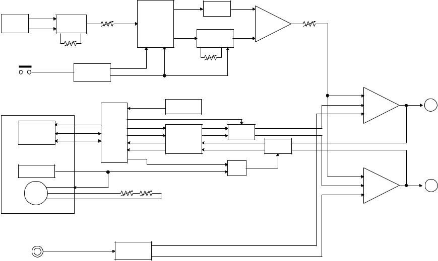
HOT1 |
|
|
Guitar Volume |
|
Filter |
|
|
|
|
|
|
Hum |
Distortion |
IC53 |
|
Guitar MIX |
|
|
||
|
Pickup |
|
|
|
|
Mixer |
|
|
||
|
|
|
Changeover |
|
|
|
|
|||
|
|
Cancel |
|
|
|
IC53 |
|
|
||
|
|
|
|
T54, T55 |
|
|
|
|
||
|
HOT2 |
|
|
VR11 |
Distortion |
|
VR52 |
|
|
|
|
|
|
|
|
|
Circuit |
|
|
|
|
|
Distortion |
|
VR13 |
|
VR51 |
|
|
|
|
|
|
Button |
|
|
|
|
|
|
|
|
|
|
|
|
|
Distortion Volume |
|
|
|
|
||
|
|
|
Flip-Flop |
|
|
|
|
|||
|
|
|
|
|
|
|
|
|
||
|
|
|
T51, T52 |
|
|
|
|
|
|
|
|
|
|
|
|
|
|
|
GUITAR-R |
|
|
|
Cassette Mechanism |
|
Bias Circuit |
T41, L41 |
|
TAPE-R |
Mixer R |
A |
||
|
|
|
|
|||||||
|
|
|
|
|
AUX-R |
IC42 |
|
|||
|
|
|
|
|
|
|
|
|
||
|
|
|
BIAS |
REC |
|
|
|
|
|
|
— |
Head |
|
L-CH |
Switch |
Head Amp. |
|
Mute |
|
|
|
|
|
S41 |
|
T45, T46 |
|
|
|
|||
3 |
|
|
|
TA8142AP |
|
|
|
|
||
— |
|
|
R-CH |
|
|
|
Mute |
|
|
|
|
|
|
IC41 |
|
|
|
|
|||
|
|
|
|
|
|
|
|
T43, T44 |
|
|
|
Leaf Switch |
|
|
|
|
T42 |
GUITAR-L |
|
|
|
|
SVC |
|
MVC (Motor Drive Signal) |
|
|
|
|
|||
|
|
+ |
|
|
|
TAPE-L |
Mixer L |
B |
||
|
|
|
|
|
|
|
||||
|
|
|
|
|
|
|
AUX-L |
IC42 |
||
|
Motor |
A |
|
|
Tape Speed Volume |
|
|
|||
|
|
|
|
|
|
|
|
|||
|
|
B |
|
|
|
|
|
|
||
|
|
|
VR31 |
VR32 |
|
|
|
|
|
|
|
|
|
|
|
|
|
|
|
||
|
Line IN |
|
|
|
RAUX |
|
|
|
|
|
|
|
|
|
|
|
|
|
|
|
|
|
|
|
|
Line IN Amp. |
|
|
|
|
|
|
|
|
|
|
|
LAUX |
|
|
|
|
|
|
|
|
|
T21, T22 |
|
|
|
|
|
|
DIAGRAMS BLOCK
|
|
|
|
Headphone Amp. |
|
|
Main Volume |
|
|
LA4525 |
IC21 |
|
|
|
|
|
|
A |
VR53 |
|
|
|
|
|
RVOUT |
|
|
|
|
|
|
|
|
|
|
|
|
|
Mixer |
Power Amp. |
|
|
|
|
LA4127 |
IC13 |
|
|
|
|
|
||
B |
|
LVOUT |
IC12 |
|
|
|
|
|
|
|
|
|
|
|
|
Mute |
|
|
|
VC 9 V |
VCC 9 V |
T23 |
|
|
|
|
|
||
DC IN 9V |
Power Switch |
Power Supply Circuit |
|
|
|
|
|
|
|||
|
S21 |
|
D22, T24 |
|
|
— 4 —
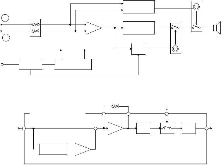
Distortion Volume
VR51
Phone Output
Speaker
Guitar Output
< DISTORTION CIRCUIT >
+ |
Amp. |
Clipper |
|
Filter |
|
IC52 |
DI505~DI508 |
T56 |
IC52 |
 Band-Pass Filter
  Amp.
Amp.
IC51
IC51
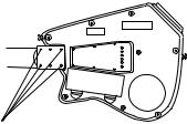
DISASSEMBLY INSTRUCTIONS
Note: EG-5 has a detachable neck. So do not loosen the four black screws attaching the neck to the body at usual repairs. Only when replacing the neck, remove the screws.
Black Screws
< Figure 1 >
To open the lower body
1.Remove the battery cover.
2.Remove the eighteen screws holding the lower body.
3.Open the lower body.
To disassemble the cassette mechanism
1.Open the lower body.
2.Desolder PC cable, JD cable and PH cable on JCM370-MA4M PCB.
3.Remove three screws on JCM370-MA2M PCB and four screws on JCM370-MA4M PCB.
4.Remove all buttons from the cassette mechanism.
5.Remove the four screws holding the cassette mechanism.
6.Remove the cassette mechanism from the upper body.
To disassemble the pickup
1.Remove all strings from the guitar.
2.Open the lower body.
3.Desolder the cable of the pickup on JCM370-MA1M PCB.
4.Remove two black screws on the upper body.
To disassemble the bridge
1.Remove all strings from the guitar.
2.Remove four screws on the bridge.
To disassemble the neck
1.Remove all strings from the guitar.
2.Remove the four black screws on the lower body.
— 5 —

TUNING
Most guitar players tune their guitar by themselves as they like.
Do not adjust tunings of a customer’s guitar at usual repairs, because the tunings may be re-adjusted by a customer. Only after replacing the neck, the bridge or the pickup, adjust a certain tuning item shown in the following table.
|
|
|
|
|
Items to be tuned |
Replaced Part |
|
|
|
|
|
|
Warp of neck |
Neck |
|
|
|
|
|
|
Pickup height |
Pickup |
|
|
|
|
|
|
String height |
Bridge |
|
|
|
|
|
|
Octave pitch |
Bridge |
|
|
|
|
|
|
|
|
|
Tools/Equipments required
4 mm hexagon key (Accessory tool)
1.5 mm hexagon key (Accessory tool) Guitar tuning meter
TUNING PROCEDURE
Please refer to the tuning instructions in the operation namual also.
To adjust warp of neck
1.Check the space between a string and the 10th fret when pressing the string at the 1st fret and at the 19th fret.
And check all strings.
2.If the space exceeds 0.3 mm, straighten the neck by turning the nut in the head clockwise with a 4 mm hexagon key.
To adjust pickup height
1.Press a string at 22nd fret.
2.Use a screw driver, adjust a height of the pickup to be 2 mm off from the string by turning two screws at both ends of the pickup.
To adjust string height
1.Use a 1.5 mm hexagon key, adjust a height of the 1st string to be 2 mm above the 14th fret by turning two hexagon socket screws at the 1st saddle in the bridge.
2.Adjust height of other strings by the same way.
To adjust octave pitch
1.Use a guitar tuning meter, tune the 1st string at open string to the standard pitch.
2.Use a guitar tuning meter, compare pitch of two tones, a tone at the 12th fret with a harmonic*.
3.If pitch of the tone at the 12th fret is sharper over 3 cents than pitch of the harmonic tone, turn the adjustment screw clockwise.
4.If pitch of the tone at the 12th fret is flatter over 3 cents than pitch of the harmonic tone, turn the adjustment screw counterclockwise.
5.Repeat steps 1 to 4 until the differnce of pitch between two tones is within 3 cents.
6.Adjust octave pitch of other strings.
* Harmonic: An overtone produced by touching a string above the 12th fret with a finger and by picking the string just before freeing the string.
— 6 —
 Loading...