

Page 1
CTK-2080
INDEX
JUL. 2011
CTK-2080
ELECTRONIC KEYBOARD
Ver. 2 : Feb. 2012
Page 2

CTK-2080
CONTENTS
SPECIFICATIONS ........................................................................................... 1
BLOCK AND WIRING DIAGRAM .................................................................. 3
PCB INFORMATION ....................................................................................... 4
CIRCUIT DESCRIPTION ................................................................................ 5
PRINTED CIRCUIT BOARDS ......................................................................... 6
DISASSEMBLY ............................................................................................... 9
DIAGNOSTIC PROGRAM ............................................................................ 19
EXPLODED VIEW ......................................................................................... 26
PARTS LIST .................................................................................................. 27
SCHEMATIC DIAGRAMS ............................................................................. 30
Page 3

SPECIFICATIONS
Keyboard 61 standard size keys
Maximum Polyphony 48 notes (24 for certain tones)
Tones
Built-in Tones 400
Sampling Tones 1 (Full Sampling) or 3 (Short Sampling)
Sampling Time: 1 second (Full Sampling) or
approximately 0.3 seconds each (Short Sampling)
Effects: 10 types (for Full Sampling samples)
Reverb 1 to 10, Off
Voice Pad 5 pads × 4 sets
(3 sets for sampled sounds, 1 set for percussion only)
Metronome
Beats per Measure 0, 2 to 6
Tempo Range 30 to 255
CTK-2080
Song Bank
Tunes 110
Step Up Lesson
Lessons 4 (Listen, Watch, Remember, Auto)
Lesson Part L, R, LR
Functions Repeat, Voice Fingering Guide, Note Guide, Performance Evaluation
Music Challenge 20 notes
Auto Accompaniment
Rhythm Patterns 150
One Touch Presets 150
Other Functions
Transpose ±1 octaves (-12 to +12 semitones)
Tuning A4 = 415.5 to 465.9 Hz (Initial Default: 440.0 Hz)
MIDI 16 multi-timbre received, GM Level 1 standard
Musical Information Function Tone, Rhythm, Song Bank numbers and names, staff notation,
ngering, pedal operation, tempo, measure and beat number,
chord name, etc.
Inputs/Outputs
USB port TYPE B
Sustain jack Standard jack (sustain, sostenuto, soft, rhythm)
Phones/Output jack Stereo standard jack
Output Impedance: 200 Ω, Output Voltage: 4.5 V (RMS) MAX
Audio In jack Stereo mini jack
Input Impedance: 9 kΩ, Input Sensitivity: 200 mV
Power Jack 9.5 V DC
– 1 –
Page 4

Power Supply 2-way
Batteries 6 AA-size zinc-carbon batteries or alkaline batteries
Battery Life Approximately 3 hours continuous operation on alkaline batteries
AC Adaptor AD-E95100L
Auto Power Off Approximately 6 minutes (during battery operation) or 30 minutes
(during AC adaptor operation) without any operation
Speakers 10 cm × 2
Output 2 W + 2 W
Power Consumption 9.5 V 7.7 W
Dimensions 94.6 × 30.7 × 9.2 cm (37 1/4 × 12 1/16 × 3 5/8 inch)
Weight Approximately 3.4 kg (7.5 lbs) (without batteries)
CTK-2080
– 2 –
Page 5
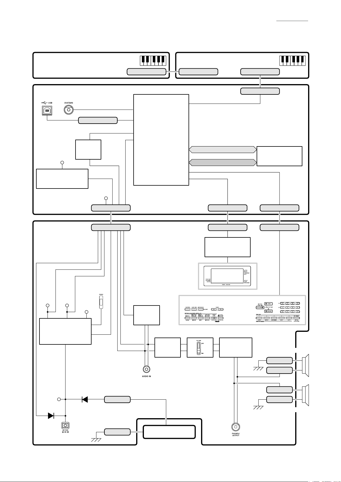
BLOCK AND WIRING DIAGRAM
KEYBOARD PCB (M800-KYA1) KEYBOARD PCB (M800-KYA2)
CN801 (13 pin) CN803 (16 pin)CN802 (13 pin)
CTK-2080
MAIN PCB (M822-MDA1)
USB
PEDAL (J1)
CN8 (4 pin)
Filter
VD3
Power Supply Circuit
IC6, C24, C25, C27,
C33, C35, C183
IC5
VD5
SUB PCB
(M822-PSA1)
ADIN
LOUT, ROUT
VA5
CN1 (11 pin)
AUDIO IN,
ADIN, APO,
STBY_CTL
MPU
LSI1
FI0~FI3, SI0~SI3, KC0~KC7
MA1~MA22
MD0~MD15
DB4~DB7,
E, R/W, RS, NMI
CN2 (10 pin) CN6 (12 pin)
CN301 (10 pin) CN302 (12 pin)CN101 (11 pin)
LCD
Controller/Driver
IC301
CN4 (16 pin)
Flash Memory
(16 Mbit)
LSI2
KC0~KC7,
KI1, KI2,
FI9, FI10
POWER SWITCH
(SW301, SW302)
VD5
Power Supply Circuit
C203~C205, D104, D105
D103
VA5
VA3
Power
Q101, Q102, Q106,
Supply Circuit
Q108, Q109, C185,
IC3, Q4, D1
D101
VCP
DC 9.5 V IN (J102)
APO
CN106 (+)
CN107 (-)
Filter
IC104
LOUT
ROUT
AUDIO IN (J104)
BATTERY
Filter
IC103
BUTTONS
MAIN VOL.
(SW303)
LCD
Power
Amplifier
IC101
PHONES (J103)
SPEAKER (L)
CN105 (-)
CN104 (+)
CN108 (+)
CN109 (-)
SPEAKER (R)
– 3 –
Page 6
PCB INFORMATION
M822-MDA1M822-PSA1
CTK-2080
M800-KYA1
Classifi cation Parts Name PCB Name Components
MPU, Flash Memory (16 Mbit),
Main PCB PCB UNIT/MAIN M822-MDA1
Sub PCB PCB UNIT/POWER & AMP M822-PSA1
Keyboard PCB PCB UNIT/KYA
M800-KYA1
M800-KYA2
Power Supply Circuit, Filter,
SUSTAIN Jack, USB Port
Power Supply Circuit, Power Ampli er,
Filters, LCD Controller/Driver, LCD,
Buttons, Power Switch, Main Volume,
DC 9.5 V Terminal, AUDIO IN Jack,
PHONES/OUTPUT Jack
Keyboard
M800-KYA2
– 4 –
Page 7
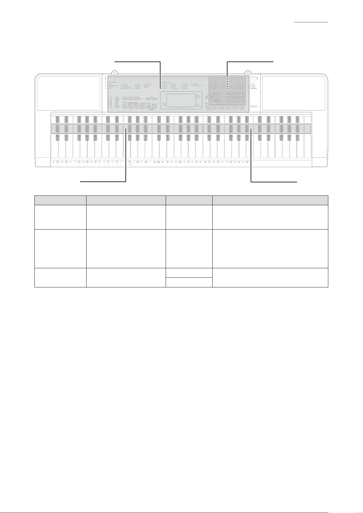
CIRCUIT DESCRIPTION
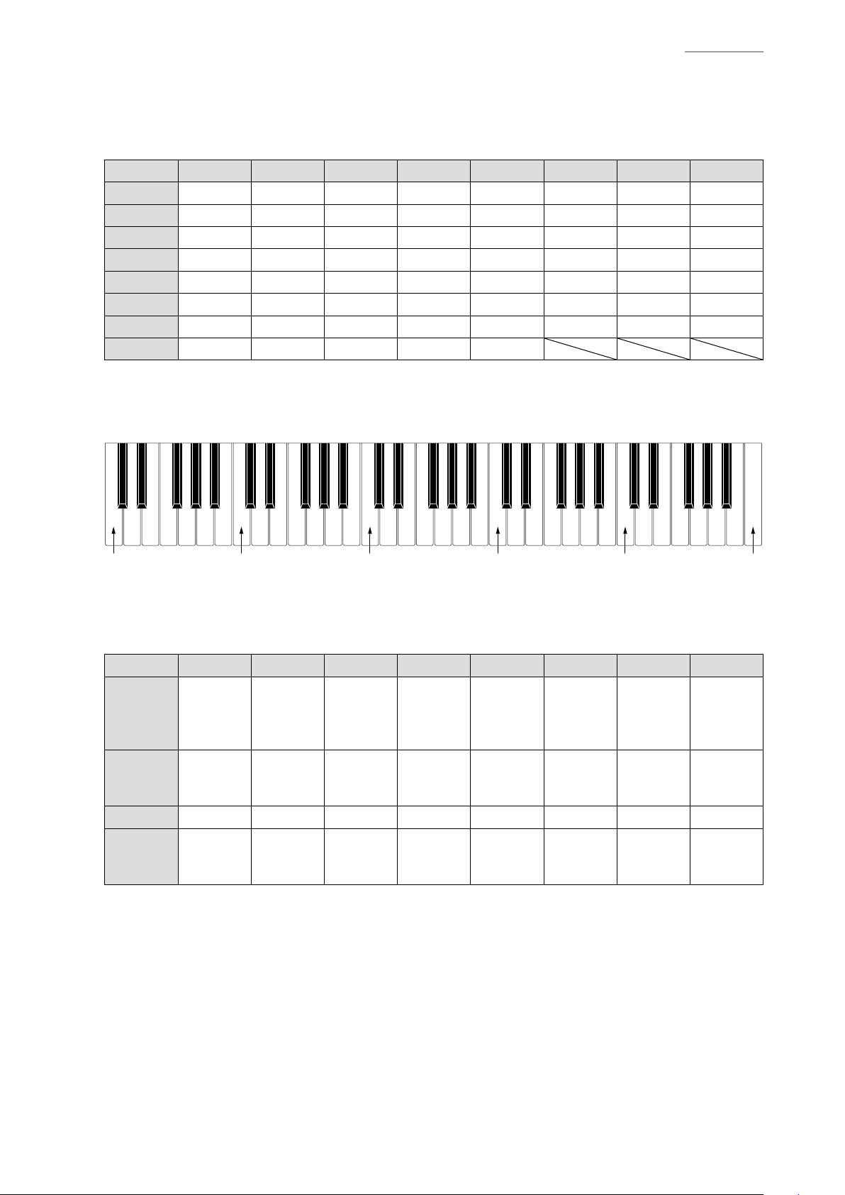
KEY MATRIX
KC0 KC1 KC2 KC3 KC4 KC5 KC6 KC7
KI0 C2 C2# D2 D2# E2 F2 F2# G2
KI1 G2# A2 A2# B2 C3 C3# D3 D3#
KI2 E3 F3 F3# G3 G3# A3 A3# B3
KI3 C4 C4# D4 D4# E4 F4 F4# G4
KI4 G4# A4 A4# B4 C5 C5# D5 D5#
KI5 E5 F5 F5# G5 G5# A5 A5# B5
KI6 C6 C6# D6 D6# E6 F6 F6# G6
KI7 G6# A6 A6# B6 C7
NOMENCLATURE OF KEYS
CTK-2080
C2
BUTTON MATRIX
KI1
RHYTHM,
KI2
FI9 0 1 2 3 4 5 6 -
FI10 7 8 9 +
ONE TOUCH
PRESET
C3
KC0 KC1 KC2 KC3 KC4 KC5 KC6 KC7
SONG
BANK
$
TONE
TEMPO
w
C4
TEMPO
q
VOICE
PAD2,
WATCH
SET SELECT,
MUSIC
CHALLENGE
VOICE
PAD3,
REMEMBER
C5
VOICE
PAD4,
NEXT
VOICE
PAD1,
LISTEN
VOICE
PAD5,
AUTO
START/
STOP,
PLAY/
STOP
NORMAL/
FILL-IN,
REW
SYNCHRO/
ENDING,
PAUSE
C6
METRONOME,
BEAT
$
FUNCTION
ACCOMP,
CHORDS,
$
PART SELECT
C7
REPEAT,
INTRO
VAR./
FILL-IN,
FF
SAMPLING
– 5 –
Page 8
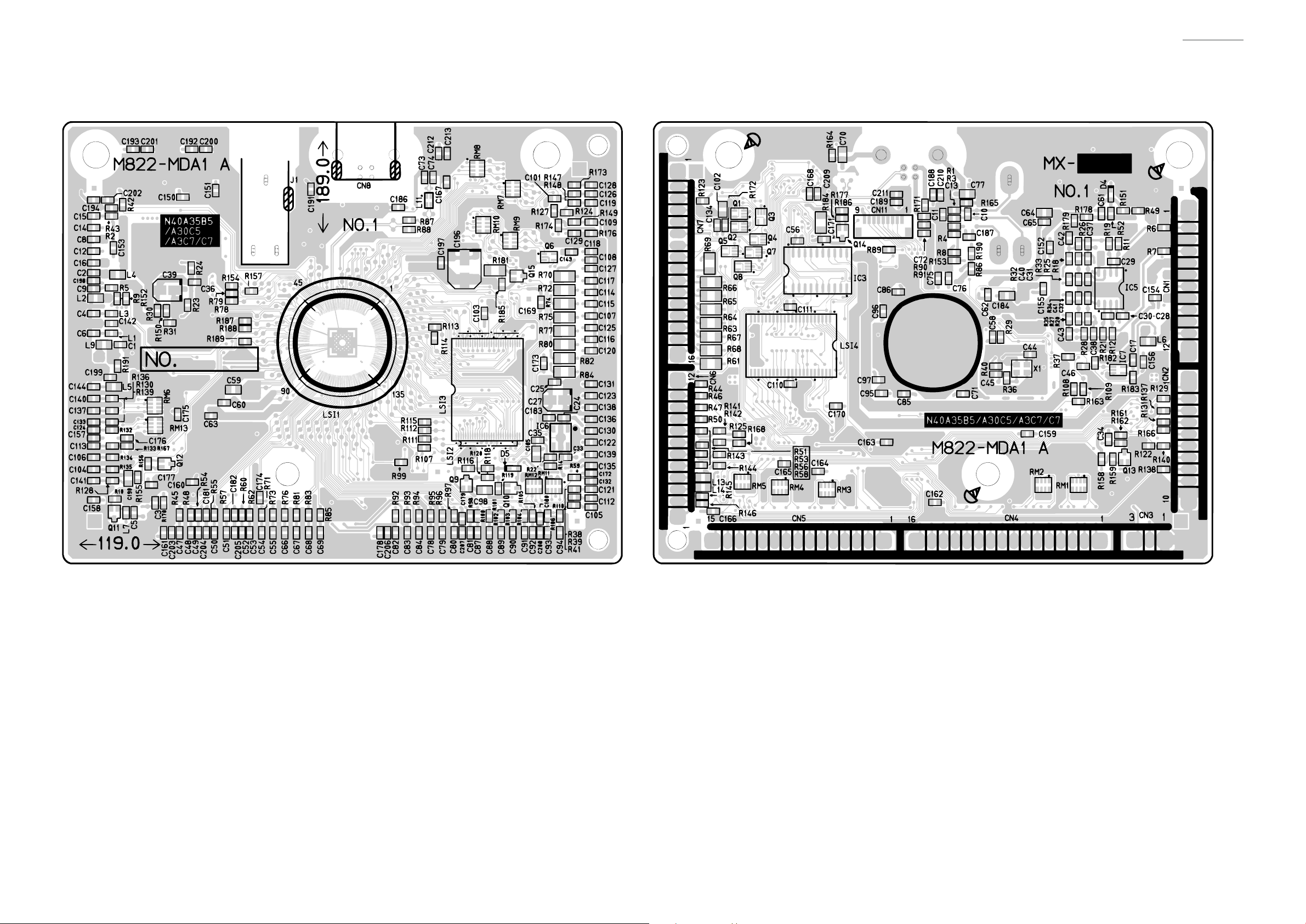
Main PCB: M822-MDA1
CTK-2080
PRINTED CIRCUIT BOARDS
– 6 –
Page 9
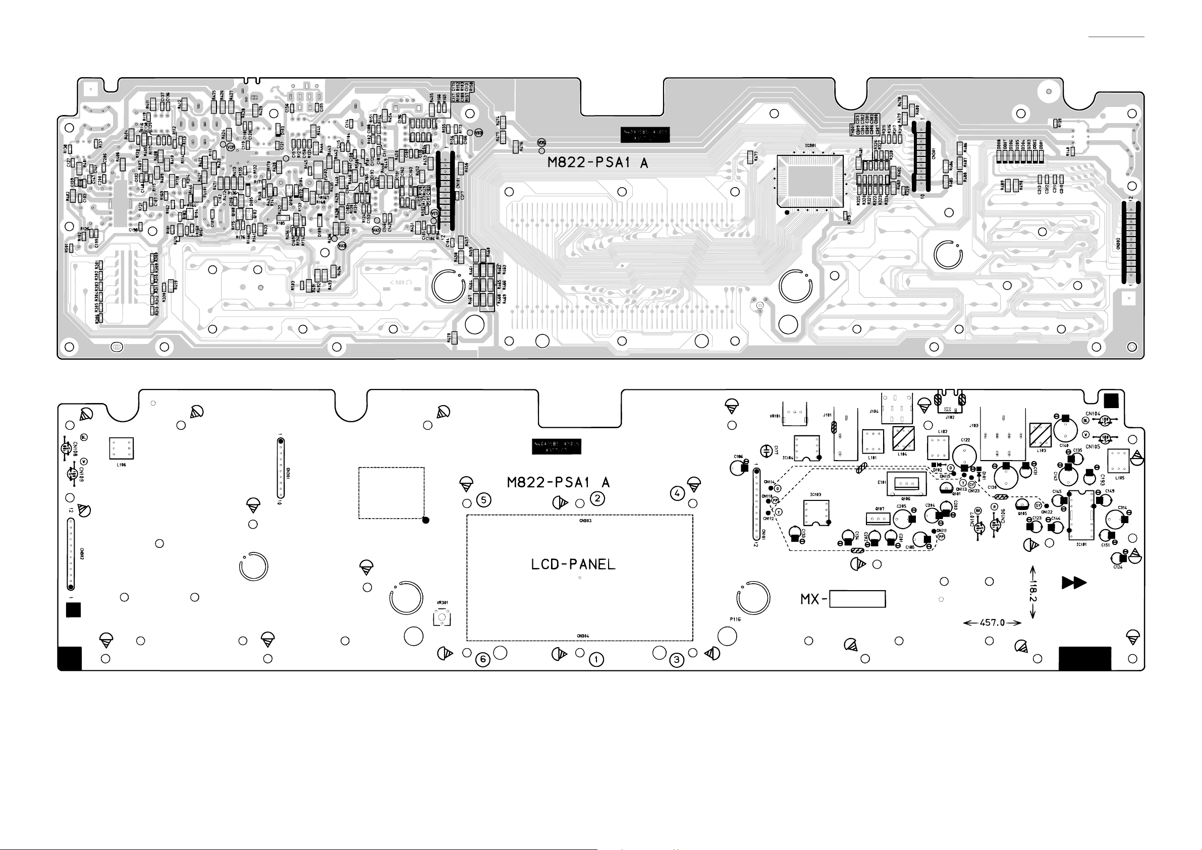
Sub PCB: M822-PSA1
CTK-2080
– 7 –
Page 10
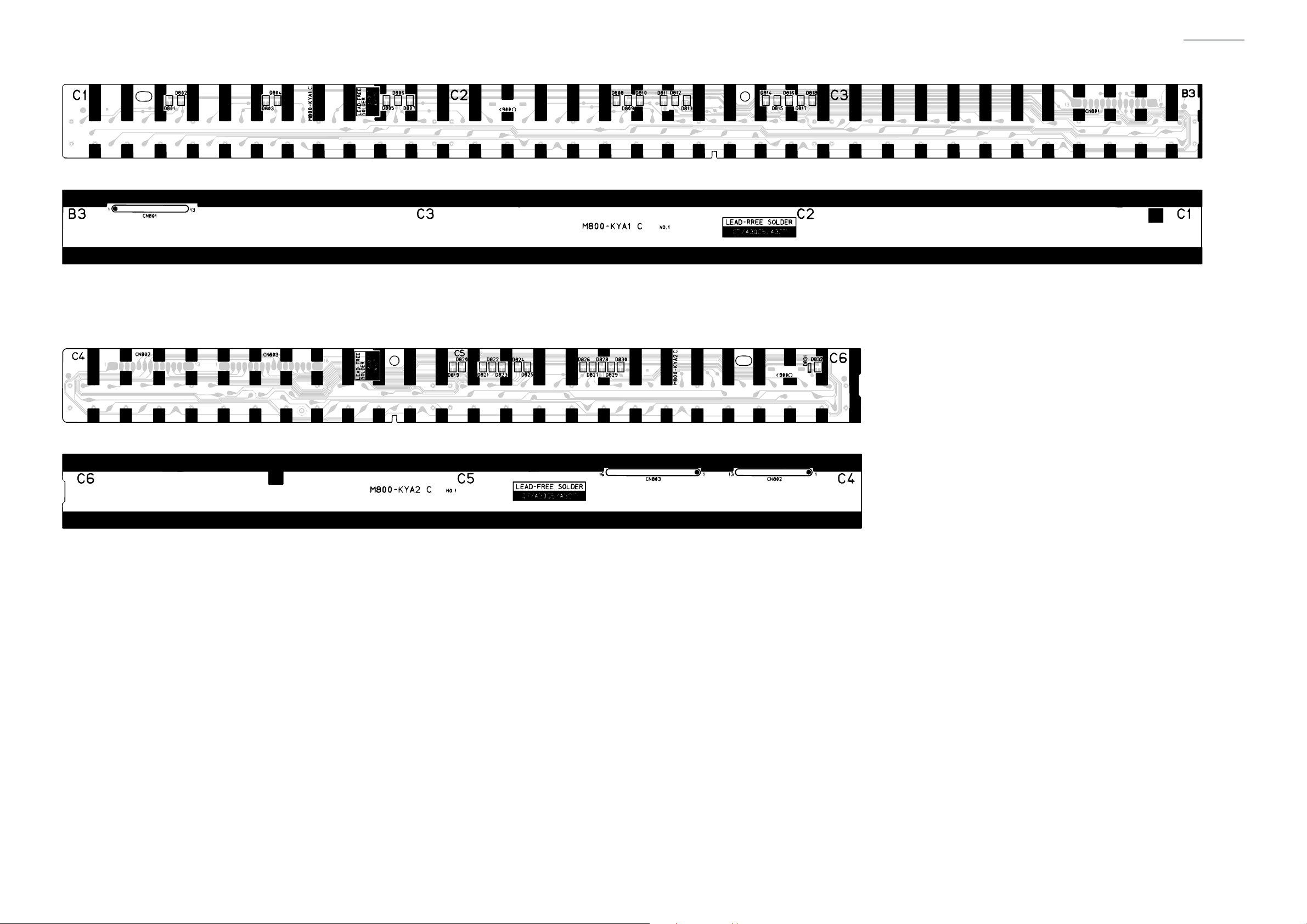
Keyboard PCB: M800-KYA1
Keyboard PCB: M800-KYA2
CTK-2080
– 8 –
Page 11
CTK-2080
DISASSEMBLY
CAUTION
z
The photos show a prototype. The appearance of the instrument, such as color, may
differ from the actual model.
z
To avoid damages to the instrument and the oor, lay the instrument on a mattress
or blanket before starting disassembling.
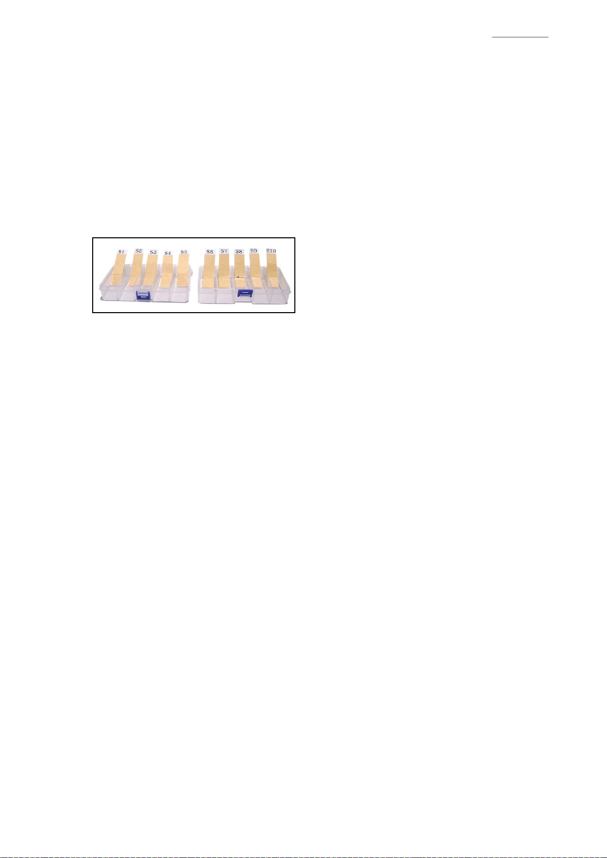
z
There are several kinds of screws. Be sure to use the correct type of screws when
reassembling. It is advisable to sort the screws as shown below after removing
them.
z
If a screw cap is attached to a screw, be sure to reattach the screw cap when
reassembling.
BEFORE STARTING REPAIR OR SERVICING
z
Remove the AC adaptor, AC cord or batteries.
z
Remove accessories such as the music stand.
– 9 –
Page 12

DISASSEMBLY
A. REMOVE THE PANEL UNITS
Main panel unit Right panel unitLeft panel unit
A-1. Undo 17 or seven screws on the bottom surface of the main unit.
NOTE: To remove only the main panel unit, undo seven screws indicated with red circles in the
illustration below.
CTK-2080
– 10 –
Page 13

A-2. Place the main unit with the keys facing up.
A-3. Lift the main panel unit and turn it over.
NOTE: The main panel unit is connected to the lower case unit with the lead wires and FFCs.
Use caution when turn over the main panel unit.
Main panel unit
CTK-2080
Lead wires
(Left speaker)
Lead wires
(Batteries)
FFC
(M800-KYA2)
Lead wires
(Right speaker)
– 11 –
Page 14

A-4. Disengage one hook and then remove the right panel unit.
A-5. Disengage one hook and then remove the left panel unit.
Hook Hook
CTK-2080
Right panel unitLeft panel unit
– 12 –
Page 15

B. REMOVE THE M822-MDA1 PCB (MAIN PCB)
B-1. Unsolder one FFC.
M822-MDA1 PCB
FFC (M800-KYA2)
B-2. Unsolder three FFCs.
B-3. Undo three screws and then remove the M822-MDA1 PCB.
CTK-2080
FFC (M822-PSA1) M822-MDA1 PCB
<Notes On Assembly>
• The number of pins on the PCB pad differs from that on the cable. Solder in the way that No.1
pin on the cable (orange) is connected to No.1 pad on the PCB.
FFC (M822-PSA1)
PCB: 12 pads
Cable: 11 pins
– 13 –
Page 16

C. REMOVE THE M822-PSA1 PCB (SUB PCB)
C-1. Unsolder four lead wires.
Lead wire (Blue)
Lead wire (White) Lead wire (Black) Lead wire (Red)
C-2. Undo 23 screws.
CTK-2080
C-3. Remove the M822-PSA1 PCB from main panel and then unsolder two lead wires.
Lead wire (Blue)
Lead wire (White)
– 14 –
Page 17

C-4. Remove the M822-PSA1 PCB, LCD components and rubber keys.
LCD componentsM822-PSA1 PCB
CTK-2080
<Notes On Assembly>
• To install the M822-PSA1 PCB, tighten the screws for the LCD part in the order indicated with
the numbers below. If not tighten correctly, it may cause the LCD display errors.
5 2 4
M822-PSA1 PCB
6 1 3
D. REMOVE THE SPEAKER
D-1. Unsolder two lead wires.
D-2. Undo four screws and then remove the SPEAKER.
<Left speaker> <Right speaker>
Lead wire (Blue)
Lead wire (White)
Lead wire (White)
Lead wire (Blue)
– 15 –
Page 18

E. REMOVE THE KEYBOARD
E-1. Undo 21 screws and then remove the keys.
CTK-2080
– 16 –
Page 19

F. REMOVE THE M800-KYA1/KYA2 PCBs (KEYBOARD PCB)
M800-KYA1 PCB M800-KYA2 PCB
F-1. Unsolder one FFC connected to the M822-MDA1 PCB.
M822-MDA1 PCB
CTK-2080
FFC (M800-KYA2)
F-2. Disengage the hooks and then remove the M800-KYA1/KYA2 PCBs.
– 17 –
Page 20

F-3. Remove ve rubber contact strips.
NOTE: One rubber contact strip differs in length.
CTK-2080
Rubber contact strips
<How To Install Rubber Contact Strips>
• Lightly insert the tip of a rubber contact strip into the
PCB. Pull the tip from the back of the PCB and install
it using a tool such as tweezers. Do not forcibly pull it.
This rubber contact strip differs
from the others in length.
– 18 –
Page 21

DIAGNOSTIC PROGRAM
PREPARATION
(1) Connect the AC adaptor.
NOTE: “AC ADAPTOR CHECK” cannot be performed unless the AC adaptor is connected.
(2) Turn the main volume to the maximum.
(3) Have a PC and a USB cable ready.
NOTE: “USB CHECK” cannot be performed without a PC and a USB cable.
Operating System: Windows® XP (SP2 or later) *1
Windows Vista® *2
Windows 7® *3
Mac OS® X (10.3.9, 10.4.11, 10.5.8 or later, 10.6.6 or later)
*1: Windows XP Home Edition/Windows XP Professional (32 bit)
*2: Windows Vista (32 bit)
*3: Windows 7 (32 bit, 64 bit)
CTK-2080
HOW TO START THE DIAGNOSTIC PROGRAM
(1) Hold down the “0”, “1” and “2” buttons at the same time, to turn the power ON.
NOTE: Be sure to turn OFF the power when the test is nished.
(2) Release the “0”, “1” and “2”
(3) After the diagnostic program is launched, the test mode screen appears.
buttons.
– 19 –
Page 22

CTK-2080
TEST ITEMS
Pressing a test button after the diagnostic program was launched or while on the main screen enables
the corresponding test item to be tested.
Test Items Buttons Note
A. BUTTON CHECK 1
B. AC ADAPTOR CHECK 3 AC adaptor
C. ROM VERSION & MODEL CHECK 9
D. LCD CHECK 2
E. USB CHECK PC, USB cable
<Test Mode Main Screen>
TEST PROCEDURES
A. BUTTON CHECK
A-1. Press the “1” button to select the “BUTTON CHECK”.
– 20 –
Page 23

A-2. Press the button in the order indicated in the illustration.
NOTE: You cannot cancel this check procedure mid-way.
<If the result passes>
The conrmation chord sounds and “1:SW00XX” is displayed on the LCD with “XX” indicating the
corresponding button number in the illustration.
<If the result fails>
If there is a button failure or the buttons are pressed in a wrong sequence, an error tone sounds
and the button number which you pressed will be displayed on the LCD.
CTK-2080
START
1F
03
1E 1D 09 08
04 05 06 07 1C
00
01
02
0D 0A 0B 0E 0C 0F
– 21 –
1A
1B
10
1211
SW OK!
191817
161514
Page 24

CTK-2080
A-3. When the “3” button is pressed at the end, a conrmation chord sounds and “SW OK!” is displayed
on the LCD.
A-4. Check to see if the LCD is as shown below.
A-5. Press the “0” button to return to the main screen.
B. AC ADAPTOR CHECK
B-1. Press the “3” button to select the “AC ADAPTOR CHECK”.
B-2. Make sure that a value “X” shown in the illustration is in the range of 1 to 3.
B-3. Press the “3” button again.
B-4. Make sure that a value “XX” shown in the illustration is in the range of 00 to FF.
B-5. Press the “0” button to return to the main screen.
– 22 –
Page 25

C. ROM VERSION & MODEL CHECK
C-1. Press the “9” button to perform the “ROM VERSION CHECK”.
The ROM version appears on the LCD.
C-2. Check that the ROM version is “18376”.
C-3. Press the “9” button to perform the “MODEL CHECK”.
The model name appears on the LCD.
C-4. Check that the model name is “MX822”.
CTK-2080
C-5. Press the “0” button to return to the main screen.
– 23 –
Page 26

D. LCD CHECK
D-1. Press the “2” button to select the “LCD CHECK”.
D-2. Press the “2” button and check to see if all LCDs are lit.
CTK-2080
D-3. Press the “2” button and check to see if all LCDs are turned off.
D-4. Press the “0” button to return to the main screen.
– 24 –
Page 27

CTK-2080
E. USB CHECK
NOTE: The following procedures are for a PC with Windows XP.
E-1. Connect the main unit to the PC with a USB cable.
E-2. Open the windows “Device Manager”, and then make sure “USB Audio Devices” is listed under
“Sound, video and game controllers”.
E-3. Disconnect the USB cable.
E-4. Verify “USB Audio Devices” is not listed under “Sound, video and game controllers”.
– 25 –
Page 28

EXPLODED VIEW
CTK-2080
19
22
24
21
23
4
5
6
7
8
13
12
8-1
14
11
15
2
9
10
16
7
22
17
18
1
23
25
24
20
21
27
34
35
36
42
40
43
25
39
41
45
38
35
37
46
37-1
36
26
29
28
31
30
32
47
33
32
3
44
– 26 –
Page 29

PARTS LIST
CTK-2080
Notes:
1. Pricesandspecicationsaresubjecttochange
withoutpriornotice.
2. Refertothelatest“PartsPriceCode”at
“PARTSFINDER”ontheCasioServiceWEBsite
(https://www.servicecasio.com).
3. Asforsparepartsorderandsupply,referto
the“GUIDEBOOKforSparepartsSupply”,
publishedseparately.
4. Thenumbersinitemcolumncorrespondto
thesamenumbersindrawing.
– 27 –
Page 30

CTK-2080_US
CTK-2080
N Item Code No. Parts Name Specification Q'ty
MAIN PCB
N 1 10401017 PCB UNIT/MAIN TK-RJM511249*001 1 A MDA1
J1 10206815 JACK/PEDAL JY-6314*01-030 1 B
CN8 10236624 CONNECTOR/USB UBR24-4K5G00 1 C
L11 10193074 COIL DLW21HN181SQ2L 1 X
D4 10009218 DIODE 1SS400TE61 1 X
IC5 10211950 IC NJM2068M-D(TE1) 1 X
N IC6 10398240 IC XC6402FV36PR-G 1 X
N LSI2 10396644 MEMORY MX29LV160DBTI-70G 1 C
X1 10375016 RESONATOR 7V48080006 1 X
N Q12,Q13 10399706 TRANSISTOR DSC500100L 2 X
SUB PCB
N 2 10401018 PCB UNIT/POWER & AMP TK-RJM511239*001 1 B PSA1
L103,L104 10231919 COIL RB53-856396NP 2 X
L102,L105,L106 10231920 COIL RB53-856397NP 3 X
J102 35015103 JACK/DC HEC3110-01-010 1 A
J103 10305218 JACK/PHONE JY-6316B*01-070 1 B
J104 10305131 JACK/AUDIO IN ST-3529B 1 B
IC103,IC104 10206677 IC NJM2068D-D 2 C
N IC101 10370338 IC TA8227APG-D12-H-T 1 X
IC301 10222381 LSI ST7066U-0A-QG 1 C
Q106 10206835 TRANSISTOR KTA1046-Y-U/P 1 X
VR301 69304870 VARIABLE RESISTOR EVND8AA03B53 1 X Contrast for LCD
D103,D104,
D301-D308
D101,D102 10261170 DIODE SRT14-A2 2 X
D105 23603102 DIODE UDZSTE-175.1B 1 X
TH301 10245365 THERMISTOR TSM1A103J34D3RZ 1 X
Q102,Q104,
N
Q108,Q109
Q105 10217742 TRANSISTOR KTA1270-Y-AT/P 1 X
Q101 10206675 TRANSISTOR KTA1273-Y-AT/P 1 X
23901820 DIODE 1SS355TE-17 10 X
10399706 TRANSISTOR DSC500100L 4 X
Price
Code
R Remarks
KEYBOARD PCB
3 10401014 PCB UNIT/KYA TK-RJM508609*003 1 C KYA1/KYA2
D801-D830,D832 10301580 DIODE LM1MA142WAT1G 31 X
PANEL UNIT
N4 10402407 DISPLAY PLATE RJM511072-001V02 1X
5 10199714 KNOB/SLIDE RJM503803-002V01 1 X
N 6 10400571 CASE/PANEL RJM511042-002V01 1 X
7 69276630 FABRIC TAPE/8X15 M440832-1 2 X
8 69270510 SLIDE CONTACT/8D CSB-08D 1 X
8-1 10417025 FABRIC TAPE/SL RJM511833-001V01 1 X
N9 10402514 SHEET/for fireproofing RJM511371-001V02 1X
N 10 10405127 LCD ZAS-TY012725DN00 1 X
11 10301465 RUBBER CONNECTOR/for LCD RJM508539-001V01 2 X
N 12 10400577 RUBBER BUTTON/A RJM511051-001V01 1 X
N 13 10400579 RUBBER BUTTON/B RJM511052-001V01 1 X
N 14 10400581 RUBBER BUTTON/C RJM511053-001V01 1 X
N 15 10400583 RUBBER BUTTON/D RJM511054-001V01 1 X
N 16 10400585 RUBBER BUTTON/E RJM511055-001V01 1 X
N 17 10400589 RUBBER BUTTON/F RJM511056-001V01 1 X
N 18 10400591 RUBBER BUTTON/G RJM511057-001V01 1 X
– 28 –
Page 31

CTK-2080_US
CTK-2080
N Item Code No. Parts Name Specification Q'ty
SIDE PANEL UNIT
N 19 10394575 CASE/SIDE PANEL/LEFT RJM511043-001V01 1 X
N 20 10394576 CASE/SIDE PANEL/RIGHT RJM511044-001V01 1 X
N 21 10405274 PACKING/8X200 RJM511196-002V01 2 X
N 22 10264808 SPEAKER C10J01A 2 X
N 23 10402403 WIRE/BLUE 1007TASC24300B3030 2 X for Speaker (+)
N 24 10402404 WIRE/WHITE 1007TASC24300W3030 2 X for Speaker (-)
N 25 10345562 SPONGE/20X200 M440755-001V01 2 X for Speaker wires
KEYBOARD UNIT
N 26 10399802 WHITE KEY/CB TK-RJM507243*004 4 A
N 27 10399803 WHITE KEY/CS TK-RJM507244*004 1 X
28 10289646 BLACK KEY/10p RJM506595-005V02 2 A
29 10289647 BLACK KEY/5p RJM506595-006V02 1 X
30 10163902 RUBBER CONTACT/CB RJM503854-001V01 4 A
31 10163903 RUBBER CONTACT/CS RJM503855-001V01 1 X
N 32 69268840 FABRIC TAPE/4X10 M440684-1 3 X
33 10263729 SPONGE/43X180 M441123-001V01 1 X
MAIN CASE UNIT
34 10401011 CASE UNIT/MAIN TK-RJM511213*001 1 X
35 10284332 BRACKET/for STAND M440866-001V02 2 X
36 69226920 RUBBER FOOT M41361-6 4 X
N 37 10373683 FELT/LOWER LIMIT/KEYBOARD RJM508593-001V02 1 X
37-1 10317116 FELT/DAMPER/KEYBOARD RJM509138-001V01 1 X
N 38 10373681 FELT/UPPER LIMIT/KEYBOARD M440342-001V03 1 X
N 39 10400576 BATTERY TERMINAL/+ RJM511046-001V01 1 X
N 40 10380432 BATTERY TERMINAL/- M440002-001V03 1 X
41 69271060 BATTERY TERMINAL/A M440676-1 2 X
42 69271070 BATTERY TERMINAL/B M440677-1 3 X
43 10243428 BATTERY COVER TK-M340884*020 1 X
N 44 10381069 LOWER COVER/A RJM508655-001V04 1 X
N 45 10381070 LOWER COVER/B RJM508656-001V04 1 X
N 46 10381071 LOWER COVER/C RJM508657-001V04 1 X
47 10400556 LABEL/RATING RJM504373-050V02 1 X
Price
Code
R Remarks
ACCESSORIES
- 10366857 MUSIC STAND RJM510426-001V01 1 C
N - 10408260 AC ADAPTOR AD-E95100LU-P2 1 B
N - 10344814 STAND CS-30X(D) 1 X
– 29 –
Page 32

Main PCB: M822-MDA1
CTK-2080
SCHEMATIC DIAGRAMS
Not used
(to PSA1/CN101)
PEDAL
USB
(J1)
(to PSA1/
CN301)
(to PSA1/
CN302)
(to KYA2/
CN803)
– 30 –
Page 33

Sub PCB: M822-PSA1
BATTERY RIGHT SPEAKERLEFT SPEAKER
CTK-2080
(to LEFT SPEAKER)
Not used
PHONES
(J103)
DC 9.5 V IN
(J102)
AUDIO IN
(J104)
(to MDA1/
CN2)
(to RIGHT SPEAKER)
(to BATTERY)
POWER SWITCH
(SW301, SW302)
(to MDA1/CN1)
Not usd: 12 pin
(to MDA1/CN6)
MAIN VOL.
(SW303)
– 31 –
Page 34

Keyboard PCB: M800-KYA1/KYA2
Not used
CTK-2080
(to KYA1/
CN801)
(to MDA1/
CN4)
Not used
(to KYA2/
CN802)
– 32 –
Page 35

Ver. 1 : Jul. 2011
• Correction of the PARTS LIST (P28)
Ver. 2 : Feb. 2011
• Correction of the EXPLODED VIEW (P26)
• Correction of the PARTS LIST (P28 and P29)
CASIO COMPUTER CO.,LTD.
Overseas Service Division
6-2, Hon-machi 1-Chome
Shibuya-ku, Tokyo 151-8543, Japan
 Loading...