


(with price)
AP-20
ELECTRONIC KEYBOARD

CONTENTS |
|
Safety Notice ...................................................................................... |
2 |
Specifications .................................................................................... |
3 |
Block Diagram ................................................................................... |
4 |
PCB Layout ........................................................................................ |
5 |
Disassembly Instructions ................................................................. |
6 |
Circuit Description .......................................................................... |
10 |
Major Waveforms ............................................................................. |
12 |
Troubleshooting .............................................................................. |
13 |
Wiring Diagram ................................................................................ |
17 |
Exploded View ................................................................................. |
18 |
Parts List .......................................................................................... |
21 |
Schematic Diagrams ....................................................................... |
23 |
SAFETY NOTICE
CAUTION!
Danger of explosion if battery is incorrectly replaced. Replace only with the same of equivalent type recommended by the appliance manufacturer.Discard used batteries according to manufacturer's instructions.
— 2 —
|
|
SPECIFICATIONS |
|
GENERAL |
|
|
|
Number of keys |
88 |
|
|
Polyphonic: |
32-note |
|
|
Preset tones: |
10, PIANO 1, PIANO 2, ELEC. PIANO, HARPSICHORD, VIBRAPHONE, |
||
|
|
PIPE ORGAN, STRINGS, CHOIR, W.BASS (Lower tone only), |
|
|
|
E.BASS (Lower tone only) |
|
|
Layer/Split function |
||
Key transpose: |
F#-C-F |
|
|
Keyboard controls: |
Tuning curve, Baroque pitch |
||
Temperaments: |
Equal Temperament, Kirnberger III, Werckmeister, Mean-Tone, |
||
|
Just Intonation (Minor/Major), Pythagorean System |
||
Effects: |
Reverb (Room, Stage, Hall 1, Hall 2)/Chorus/Tremolo/Brilliance |
||
Demo tunes: |
8, |
1. Polonaise "Héroïque" (F.F. Chopin) |
|
|
|
2. |
Frühlingslied Op. 62-6 (F. Mendelssohn) |
|
|
3. |
CASIO original |
|
|
4. |
Harmonious blacksmith (G.F. Händel) |
|
|
5. |
CASIO original |
|
|
6. |
Jesus, Bleibet Meine Freude (J.S. Bach) |
|
|
7. |
CASIO original |
|
|
8. |
CASIO original |
Memory: |
Number of Songs: |
2 (A and B) |
|
|
System: |
|
Real-time recording |
|
Memory Capacity: |
Approximately 3,000 notes total |
|
|
Memory Backup Battery: |
Built-in lithium battery |
|
|
|
|
Battery Life: Approximately 5 years |
Pedals: |
Soft, Sostenuto, Damper |
|
|
Tuning control: |
440Hz ±50 cents |
|
|
Built-In Speakers: |
16 cm dia. x 2 (Output: approx. 20 W + 20 W) |
||
MIDI: |
16-channel, multi-timbral reception |
||
Terminals: |
PHONES 1 and 2, MIDI (IN/OUT/THRU), LINE OUT L and R (Output Imped- |
||
|
ance: 10 KΩ; Output Voltage: 2 V, RMS, max.), LINE IN R and L (Input Imped- |
||
|
ance: 20 KΩ, Input sensitivity: 200 mV) |
||
Power source: |
120V (for U.S.A.), |
|
|
|
120V, 220V, 230V and 240V (for other countries) |
||
Power consumption: |
65W (with 120V AC), 55W (with 220V, 230V and 240V AC) |
||
Dimensions (HWD): |
Without stand: |
185 × 1340 × 520 mm (7-5/16 × 52-13/16 × 20-1/2 inches) |
|
|
With stand: |
820 × 1360 × 550 mm (32-5/16 × 53-9/16 × 21-11/16 inches) |
|
Weight: |
Without stand: |
35.5 kg (78.3 lbs)/38.5 kg (84.0 lbs) |
|
|
With stand: |
45.5 kg (100.4 lbs)/48.5 kg (106.1 lbs) |
|
Note: There are two models of AP-20, one has a keyboard cover, the other has no keyboard cover.
— 3 —

RAM 256K HM62256BLP-10
ROM 1M
MX23C1010PC12CA25
|
|
|
AVCC |
|
AVDD |
AVFF |
VDD |
||
|
+12V |
|
+5V |
–12V |
|
+5V |
|||
|
|
|
Voltage Regulator |
M5F78M12L × 2 |
M527BL05 |
T8, T9 |
|||
|
|
|
|
|
|
|
|
|
|
Power Switch T101 |
|
|
|
|
|
|
|
Power Transformer |
|
|
|
|
|
|
|
|
|||
|
|
|
|
|
|
|
|||
|
|
|
|
|
|
|
|
||
|
|
|
|
|
|
|
|
|
|
BLOCK DIAGRAM
|
|
|
MIDI |
|
|
KC0 ~ 7 Keyboard |
|
|
|
IN |
OUT |
P70 ~ |
Keyboard |
|
|
PEDAL |
|
P77 |
|||||
SF |
|
|
Controller |
|
|
MIDI |
MIDO |
HG52E35P |
|
|
|
SS |
|
|
|||
DP |
|
|
|
FI0 ~ 10 |
|
|
|
|
P12 ~ |
|
|
|
|
|
SI0 ~ 10 |
Switches |
|
BRILLIANCE |
|
|
P14 |
||
|
|
KC0 ~ 4 |
|||
|
CPU |
|
|
|
|
|
|
Switch & LED |
|
|
|
HD6435328RC13F |
|
|
|
||
|
Controller |
|
|
||
|
|
|
|
|
|
|
|
|
µPD65005GF-419 KI0 ~ 3 |
|
|
|
|
L1 ~ 9 |
LEDs |
|
D0 ~ 7 |
|
LA ~ J |
||
|
RST |
Reset IC |
|
|
A0 ~ 14 |
MUTE |
MB3771P |
|
|
|
|
|
|
|
|
A0 ~ 3 |
RA0 ~ 19 |
|
|
|
|
|
|
|
|
|
|
|
ROM |
|
|
RD0 ~ 15 |
|
8M + 16M |
|
|
HN62418PD25 |
||
|
|
|
||
DSP |
|
|
HN624116D44 |
|
HG51B155FD |
EA0 ~ 14 |
|
|
|
|
|
|
RAM |
|
|
|
|
|
|
|
|
ED0 ~ 15 |
|
256K × 2 |
|
|
HM65256BLSP- |
||
|
|
|
|
10 × 2 |
SOLM, SOLP |
BDK, WOK1, SORM, SORP |
|
|
|
D/A Converter |
D/A Converter |
|
|
|
µPD6376CX |
µPD6376CX |
|
|
|
Filter |
Filter |
|
|
|
Main |
|
|
|
|
Volume |
|
|
|
|
LINE IN
Mixer, Mute Circuit
T6, T7, T10, T11
Power Amp.
STK4132MK
— 4 —

PCB LAYOUT
MA2M
PS1 MA1M
|
|
|
|
|
|
|
|
|
|
|
IF1M |
|
|
|
|
|
|
|
|
|
HALL 2 |
|
|
|
|
CONTROL |
|
VOLUME |
BRILLIANCE |
|
|
TONE |
LOWER TONE |
REVERB |
MEMORY |
|
TUNE |
DEMO |
|
|
|
|
|
|
|
|
HALL 1 |
TREMOLO |
|
CN3M |
|
ON |
MIN |
|
MAX MELLOW |
BRIGHT PIANO 1 |
PIANO 2 |
E.PIANO HARPSICHORD VIBRAPHONE PIPE ORGAN STRINGS CHOIR |
W.BASS E.BASS |
STAGE |
CHORUS |
START/ |
||
OFF |
|
|
SONG A SONG B RECORD STOP |
|||||||||
POWER |
|
CN2M |
|
|
|
CN1M ROOM |
|
|
||||
|
|
|
TP10-KY1M |
|
|
|
|
|
TP10-KY2M |
|||
MA4M MA5M |
|
|
|
|
|
|
|
|
|
|
||
Note: IF1M PCB is a terminal board for the keyboard PCBs, and included in the main PCB.
PCB |
JCM433- |
Components |
|
|
|
Main PCB |
MA1M |
CPU, DSP, Sound Source ROM Working storage |
|
|
RAM, Effect RAM Reset IC, DAC, Filter, Key con- |
|
|
troller, Power amp, Power supply circuit |
|
|
|
Jack PCBs |
MA2M |
LINE IN/OUT jack, MIDI jacks |
|
|
|
|
MA4M |
Phone jacks |
|
|
|
|
MA5M |
Power indicator |
|
|
|
Console PCBs |
CN1M |
Gate array (Button controller/LED driver), LEDs, |
|
|
Buttons |
|
|
|
|
CN2M |
Main Volume, Brilliance volume |
|
|
|
|
CN3M |
Tune Buttons, Demo button |
|
|
|
Power PCB |
PS1 |
Fuse, Noise filter |
|
|
|
— 5 —
DISASSEMBLY INSTRUCTIONS
1. Disassembling top board
1-1. Remove 8 screws on the rear.
1-2. Slide the top board towards the rear.
The top board will be free from catches on the case.
1-3. Lift the top board.
For keyboard-cover model
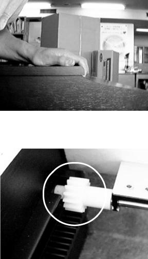
2. Disassembling keyboard cover
2-1. Slide the keyboard cover to open fully. 2-2. Passing the gear into the opening on each
rack, lift the keyboard cover.
For no-keyboard-cover model
2. Disassembling the front cover
2-1. Remove 4 screws at both ends of the front cover. 2-2. Remove the front cover.
— 6 —
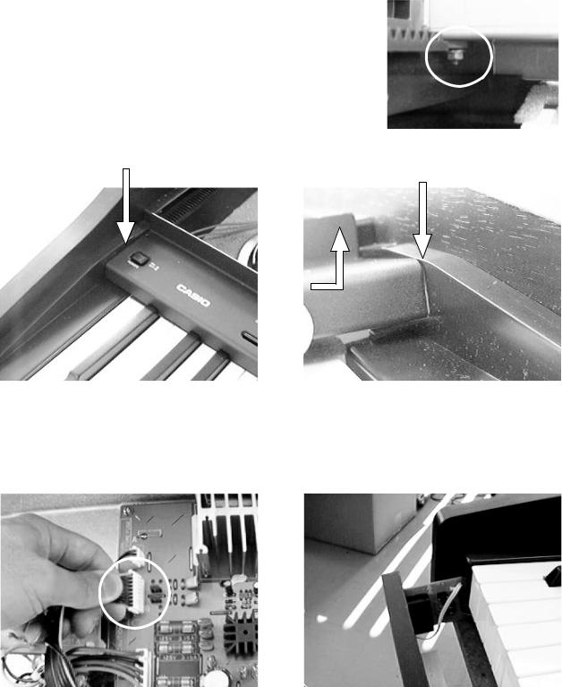
3. Disassembling console panel
Note: To avoid scratch on the side board, put paper between the console panel and the side board at both ends.
3-1. The console panel is fixed with screws and nuts. Holding the nut, remove the screw.
3-2. Remove the screw fixing a grounding wire at the transformer. 3-3. Slide the console panel towards the front to free from catches. 3-4. Turn round the console panel.
3-5. Remove the 2 screws fixing the power switch.
Insert paper here.
Insert paper here.
4. Disassembling front cover
4-1. Remove 5 screws at the front edge on the bottom.
4-2. Disconnect the connector for phone jacks from the main PCB.
4-3. Watching the phone-jack cable, pull out the front cover towards the front.
— 7 —

5. Disassembling keyboard unit
5-1. Remove 6 screws at both ends on the bottom, and a screw at the middle.
5-2. Remove 2 screws at both ends of keyboard unit.
5-3. Disconnect 2 connectors for the keyboard unit from the main PCB.
5-4. Moving the keyboard unit towards the front, remove the unit from the case.
6. Disassembling keys
6-1. Peel the red felt and sponges off the keyboard unit. 6-2. Using a long-nose plier, remove key springs.
6-3. Pressing the hook with a long-nose plier. Lift the key.
— 8 —

7. Disassembling keyboard PCBs
7-1. Turn round the keyboard unit to face the PCB up.
7-2. Disconnect the connector at the middle of keyboard.
7-3. Remove screws on the keyboard PCBs.
8. Replacing the main PCB
Note: The main PCB contains a lithium battery for memory back-up. Please remove the jumper before replacing the PCB. And make sure that the jumper is reset on new main PCB after replacing the PCB. Because no jumper is set on a spare part of the main PCB.
Jumper
— 9 —
 Loading...