


42HWG007
Carrier 42HWG007, 42HQG012, 42HQG007, 42HQG009, 42HWG012 Technical Data & Service Manual
...
INDOOR UNIT
42HWG007/009/012/018/024
42HQG007/009/012/018/024
HWG195C/225C/305C/455C/605C
HWG195H/225H/305H/455H/605H
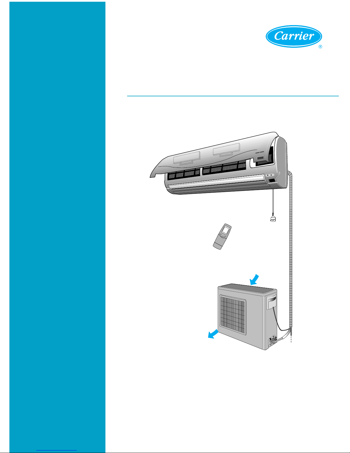
SPLIT SYSTEM AIR CONDITIONER
42HWG-Series, 42HQG-Series, HWG
...
H-Series, HWG
...
C-Series
O
N/O
FF
T
EM
P
SLE
E
P
TECHNICAL DATA & SERVICE MANUAL

1
Contents
11. SPECIFICATIONS........................................................................................................................2
12. OUTLINE AND DIMENSIONS .....................................................................................................6
13. OPERATION ................................................................................................................................7
14. WIRING DIAGRAM ....................................................................................................................29
15. REFRIGERANT CYCLE ............................................................................................................33
16. CONTROL BLOCK DIAGRAM...................................................................................................35
17. ELECTRIC CIRCUIT DIAGRAM ................................................................................................37
18. KEY COMPONENTS OF ELECTRONIC CIRCUIT ...................................................................50
19. CHECKING AND REPAIRING OF ELECTRIC PARTS..............................................................55
10. TROUBLE SHOOTING ..............................................................................................................59
11. DISASSEMBLY INSTRUCTIONS ......................................................................................61
12. EXPLODED DIAGRAM AND PARTS LIST ........................................................................63
13. EXTENDING RATINGS .....................................................................................................71
14. DIP SWITCH CONFIGURATION FOR ETO ......................................................................87
2
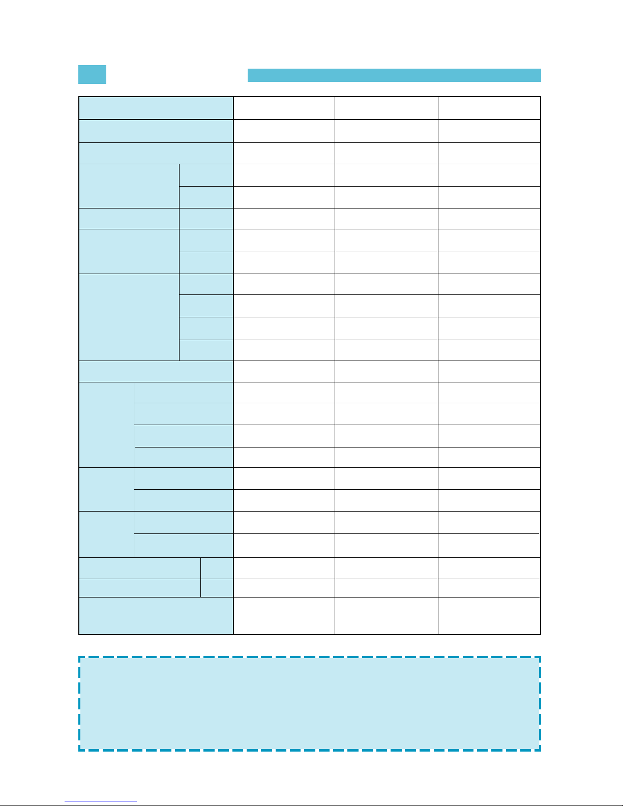
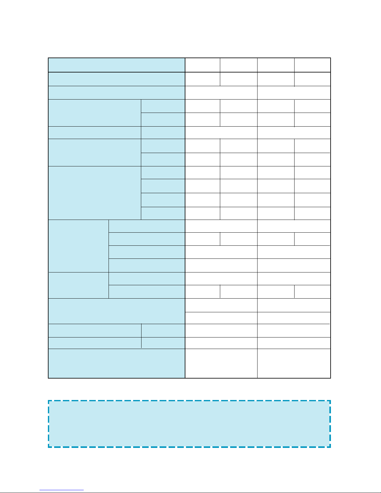
SPECIFICATIONS
1
Model
Function
Power Supply
Capacity
W
Btu/h
Dehumidification L/h
Electrical data A
(ID unit only) W
Electrical data A
(System) W
A
max (*)
W
max (*)
Type
Fan
RPM (Hi/Lo)
Capacitor
Motor Model Number
Connection
Type
OD (Liquid/Suction)
Cord
Power supplied to
connection
indoor unit
conductor
Power supplied to
size
outdoor unit
Dimension (WxHxD) mm
Net Weight Kg
OD MODEL
42HWG007/HWG195C
Cooling
230V-1PH-50Hz
2050
7000
0.8
0.11
25
3.1
700
4.2
890
Indoor unit
Cross flow fan
1000/800
1.0µF, 450V
IC-8415G1KG7A
Flare
1/4”(6.35),3/8”(9.52)
R,C,Y: 2.5mm
2
R,C,Y: 1.0mm
2
780x240x170
8
38GL--07---703EC-40
SKY195C
42HWG009/HWG225C
Cooling
230V-1PH-50Hz
2410
8300
1.0
0.11
25
4.2
930
5.6
1200
Indoor unit
Cross flow fan
1100/900
1.0µF, 450V
IC-8415G1KG7A
Flare
1/4”(6.35),3/8”(9.52)
R,C,Y: 2.5mm
2
R,C,Y: 1.0mm
2
780x240x170
8
38GL--09---703EC-40
SKY225C
42HWG012/HWG305C
Cooling
230V-1PH-50Hz
3140
10700
1.4
0.16
36
5.3
1190
8.0
1700
Indoor unit
Cross flow fan
1050/850
1.0µF, 450V
IC-9420G2KG7A
Flare
1/4”(6.35),1/2”(12.7)
R,C,Y: 2.5mm
2
R,C,Y: 1.0mm
2
815x260x185
9
38GL--12---703EC-40
SKY305C
NOTE: •
Above the datum for running current and power input mean the value
tested in the following conditions.
1) Ambient temperature : Tid=27/19ºC, Tod=35ºC in cooling.
2) (*)Severe operating conditions: Tid=32/23ºC, Tod=43ºC in cooling.
3) Voltage: 198/264V.
•
Specifications can change without notice.
3
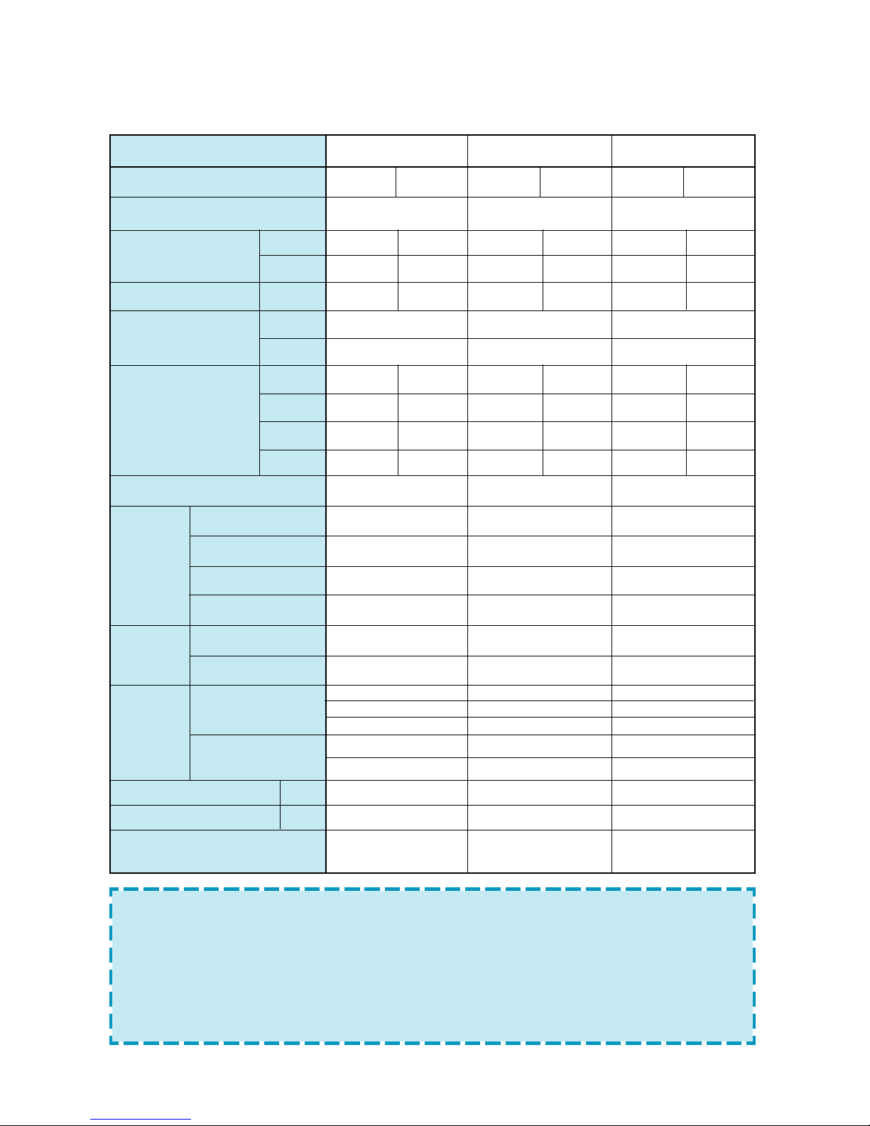
NOTE: •
Above the datum for running current and power input mean the value
tested in the following conditions.
1) Ambient temperature : Tid=27/19ºC, Tod=35ºC in cooling and
Tid=20ºC, Tod=7/6ºC in heating. Voltage 230V.
2) (*)Severe operating conditions: Tid=32/23ºC, Tod=43ºC in cooling and
Tid=27ºC, Tod=24/18ºC in heating. Voltage 198/264V.
•
Specifications can change without notice.
Model
Function
Power Supply
Capacity
W
Btu/h
Dehumidification L/h
Electrical data A
(ID unit only) W
Electrical data A
(System) W
A
max (*)
W max (*)
Type
Fan
RPM (Hi/Lo)
Capacitor
Motor Model Number
Connection
Type
OD (Liquid/Suction)
Power supplied to
Cord
indoor unit
connection
conductor
Power supplied to
size
outdoor unit
Dimension (WxHxD) mm
Net Weight Kg
OD UNIT MODEL
42HQG007/HWG195H-SERIES
Cooling Heating
220/240V-1PH-50Hz
2020 2150
6900 7340
0.8 -
0.11
25
3.24 3.06
730 690
4.5 4.6
920 890
Indoor unit
Cross flow fan
1000/800
1.0µF, 450V
IC-8415G1KG7A
Flare
1/4”(6.35),3/8”(9.52)
R,C,Y : 2.5mm
2
O.W2 : 1.0mm
2
S1,S2 : 0,75mm
2
R,C,Y,O,W2 : 1.0mm
2
S1, S2 : 0,75mm
2
780x240x170
8
38YL--07---703EJ-40
SKY195HJ
42HQG009/HWG225H-SERIES
Cooling Heating
220/240V-1PH-50Hz
2350 2740
8020 9350
1.0 -
0.11
25
4.22 4.17
950 940
5.7 5.8
1230 1230
Indoor unit
Cross flow fan
1100/900
1.0µF, 450V
IC-8415G1KG7A
Flare
1/4”(6.35),3/8”(9.52)
R,C,Y : 2.5mm
2
O.W2 : 1.0mm
2
S1,S2 : 0,75mm
2
R,C,Y,O,W2 : 1.0mm
2
S1, S2 : 0,75mm
2
780x240x170
8
38YL--09---703EJ-40
SKY225HJ
42HQG012/HWG305H-SERIES
Cooling Heating
220/240V-1PH-50Hz
3110 3250
10600 11000
1.4 -
0.16
36
5.4 4.44
1220 1020
8.1 7.0
1700 1300
Indoor unit
Cross flow fan
1050/850
1.0µF, 450V
IC-9420G2KG7A
Flare
1/4”(6.35),1/2”(12.7)
R,C,Y : 2.5mm
2
O.W2 : 1.0mm
2
S1,S2 : 0,75mm
2
R,C,Y,O,W2 : 1.0mm
2
S1, S2 : 0,75mm
2
815x260x185
9
38YL--12---703EJ-40
SKY305HJ
4
Model
Function
Power Supply
Capacity
W
Btu/h
L/h
Electrical data A
(ID unit only) W
Electrical data A
(System) W
A
max (*)
W
max (*)
Type
Fan
RPM (Hi/Lo)
Capacitor
Motor Model Number
Connection
Type
OD (Liquid/Suction)
Cord connection conductor size
(Power supplied to outdoor unit)
Dimension (WxHxD) mm
Net Weight Kg
OD UNIT
42HWG018 / HWG455C
Cooling
230V-1PH-50Hz
4690
16007
1.7
0.19
45
7.9
1780
20
2270
Cross flow fan
1150/950
1.8µF, 450V
IC-9430G4KG7A
Flare
1/4”(6.35) 1/2”(12.7)
R,C,Y: 1.0mm
2
1080x295x185
14
38GL--18---703EC-40
SKY455C
42HWG024 / HWG605C
Cooling
230V-1PH-50Hz
6240
21300
2.5
0.19
45
10.6
2420
17
3300
Cross flow fan
1250/1050
1.8µF, 450V
IC-9430G4KG7A
Flare
1/4”(6.35) 5/8”(15.88)
R,C,Y: 1.0mm
2
1080x295x185
14
38GL--24---703EC-40
SKY605C
NOTE: • Cooling capacity test is performed through temperature condition based
on 27ºC D.B., 19ºC W.B., in indoor and 35ºC D.B., 24ºC W.B. in outdoor.
• Cooling capacity test is performed at high voltage.
• Specification can change without notice.
5
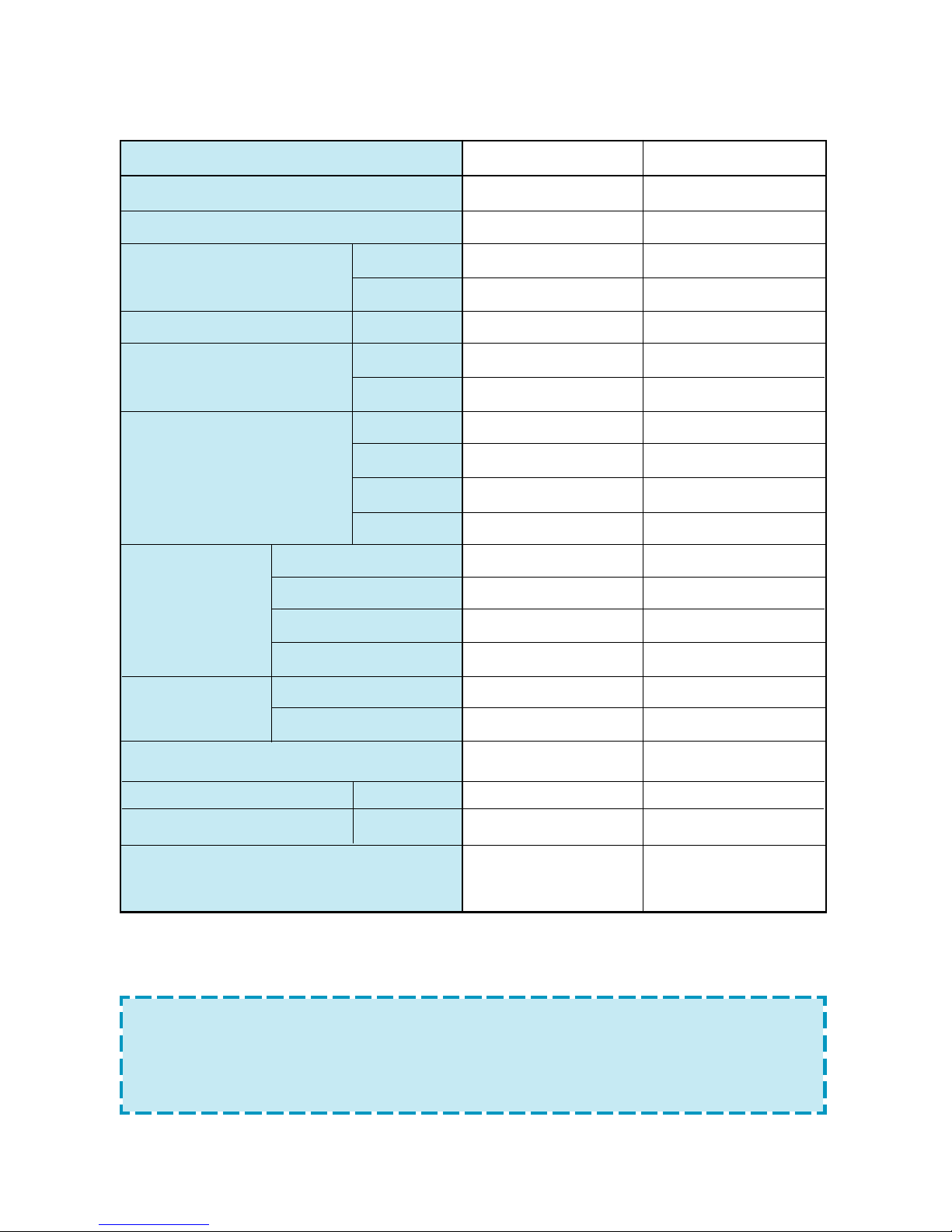
Model
Function
Power Supply
Capacity
W
Btu/h
L/h
Electrical data A
(ID unit only) W
Electrical data A
(System) W
A
max (*)
W
max (*)
Type
Fan
RPM (Hi/Lo)
Capacitor
Motor Model Number
Connection
Type
OD (Liquid/Suction)
Cord connection conductor size
(Power supplied to outdoor unit)
Dimension (WxHxD) mm
Net Weight Kg
OD UNIT
42HQG018 HWG455H
Cooling Heating
230V-1PH-50Hz
4790 5100
16360 17420
1.7
0.19 0.19
45 45
7.3 6.7
1630 1490
x 8.0
2270 1800
Cross flow fan
1150 950
1.8µF, 450V
IC-9430G4KG7A
Flare
1/4”(6.35) 1/2”(12.7)
R,C,Y,O,W2 : 1.0mm
2
S1, S2 : 0.75mm
2
1080x295x185
14
38YL--18---703EC-40
SKY455HJ
42HQG024 HWG605H
Cooling Heating
230V-1PH-50Hz
6110 7170
20886 24486
2.5
0.19 0.19
45 45
10.7 11
2430 2480
17.0 14.6
3300 2900
Cross flow fan
1250 1050
1.8µF, 450V
IC-9430G4KG7A
Flare
1/4”(6.35) 5/8”(15.88)
R,C,Y,O,W2 : 1.0mm
2
S1, S2 : 0.75mm
2
1080x295x185
14
38YL--24---703EC-40
SKY605HJ
NOTE: • Cooling capacity test is performed through temperature condition based
on 27ºC D.B., 19ºC W.B., in indoor and 35ºC D.B., 24ºC W.B. in outdoor.
• Cooling capacity test is performed at high voltage.
• Specification can change without notice.
6
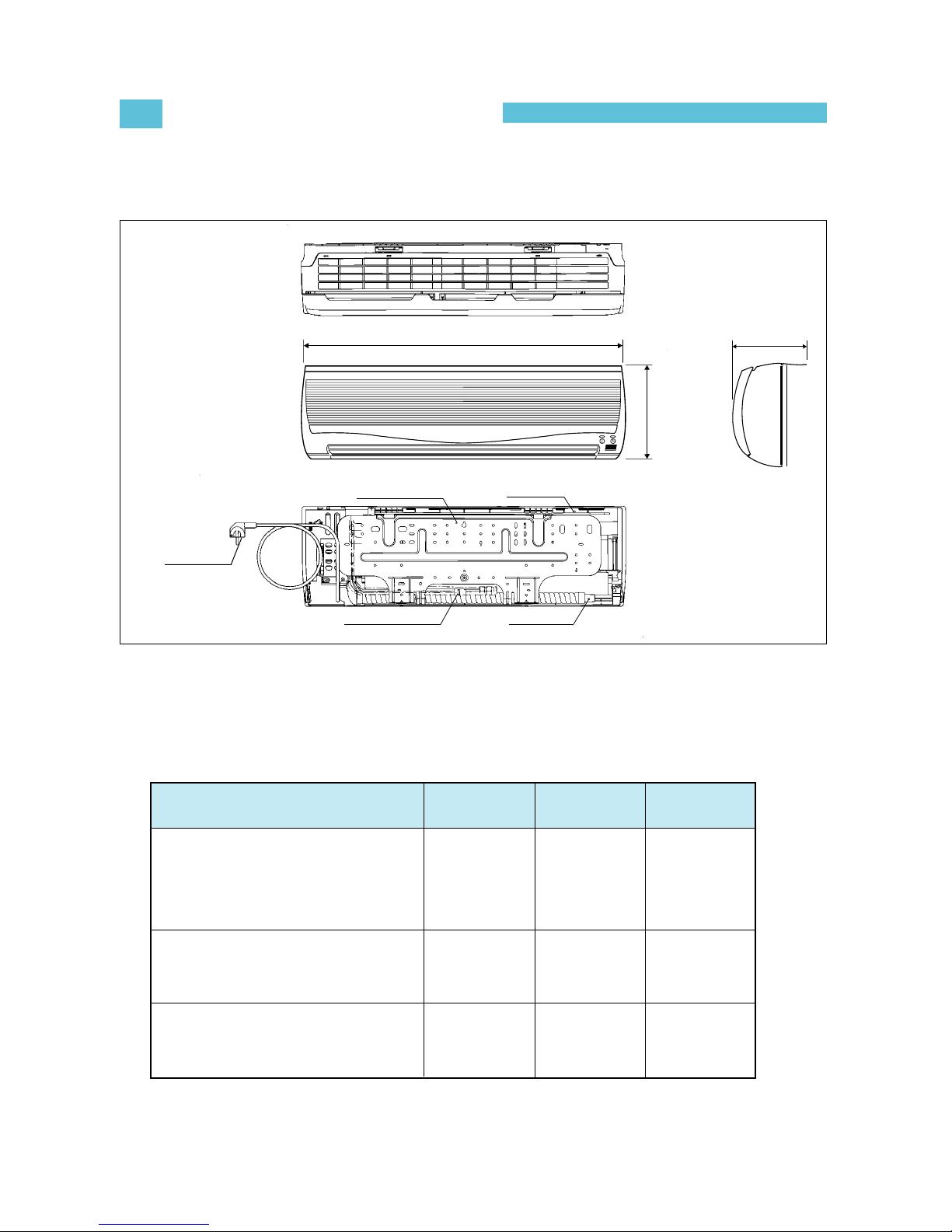
OUTLINE AND DIMENSIONS
2
INDOOR UNIT
MODEL
42HWG007/009
42HQG007/009
HWG195C/195H/225C/225H
42HWG012,42HQG012,
HWG305C/305H
42HWG018/024, 42HQG018/024,
HWG455C/455H/605C/605H
A
780
815
1080
B
240
260
295
C
170
185
185
C
A
B
MOUNTING PLATE
MAIN BODY
POWER PLUG
DRAIN HOSE
CONNECTION TUBE
7
OPERATION
3
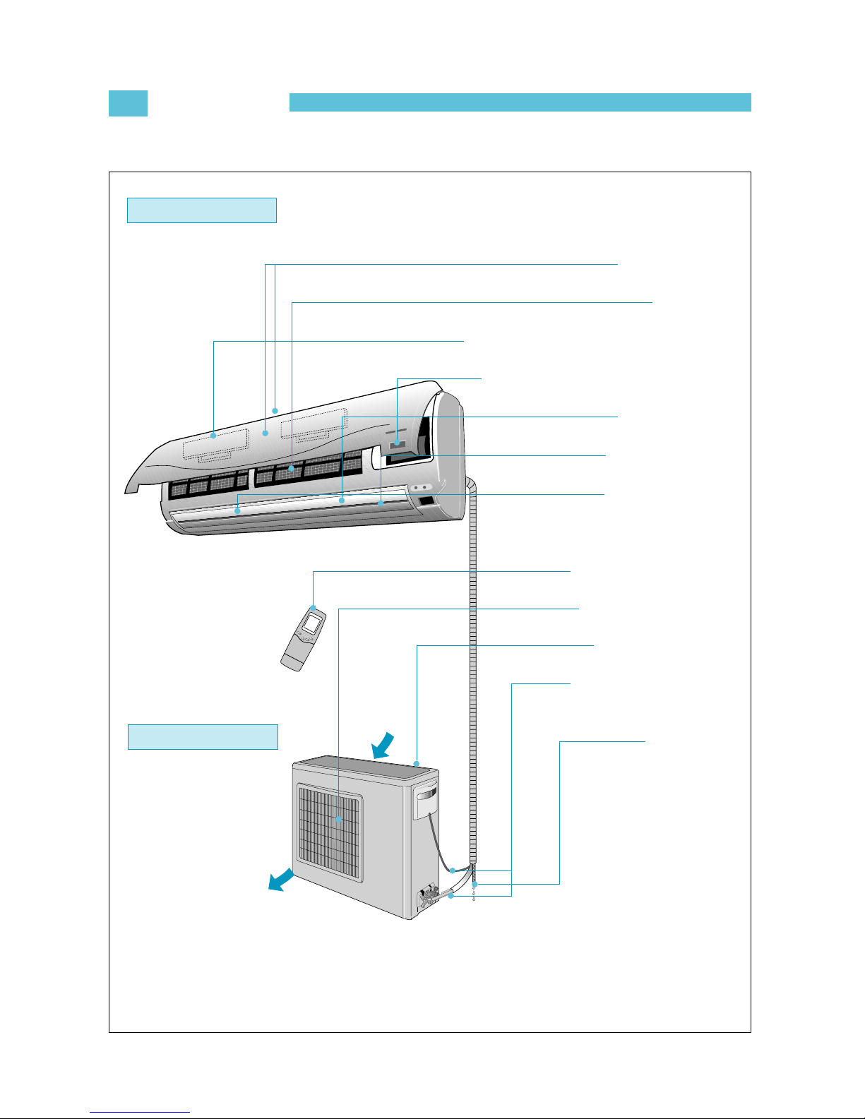
1) SYSTEM DIAGRAM
Indoor Unit
O
N
/O
F
F
T
E
M
P
S
L
E
E
P
ROOM AIR INLET
AIR FILTER
ELECTROSTATIC/ACTIVE CARBON FILTER
REMOTE CONTROL SIGNAL RECEIVER
AIR SWING FLAP
VERTICAL LOUVER
ROOM AIR OUTLET
LCD REMOTE CONTROL
OUTDOOR AIR OUTLET
OUTDOOR AIR INLET
INDOOR AND OUTDOOR
CONNECTION
DRAIN HOSE
Outdoor Unit
8
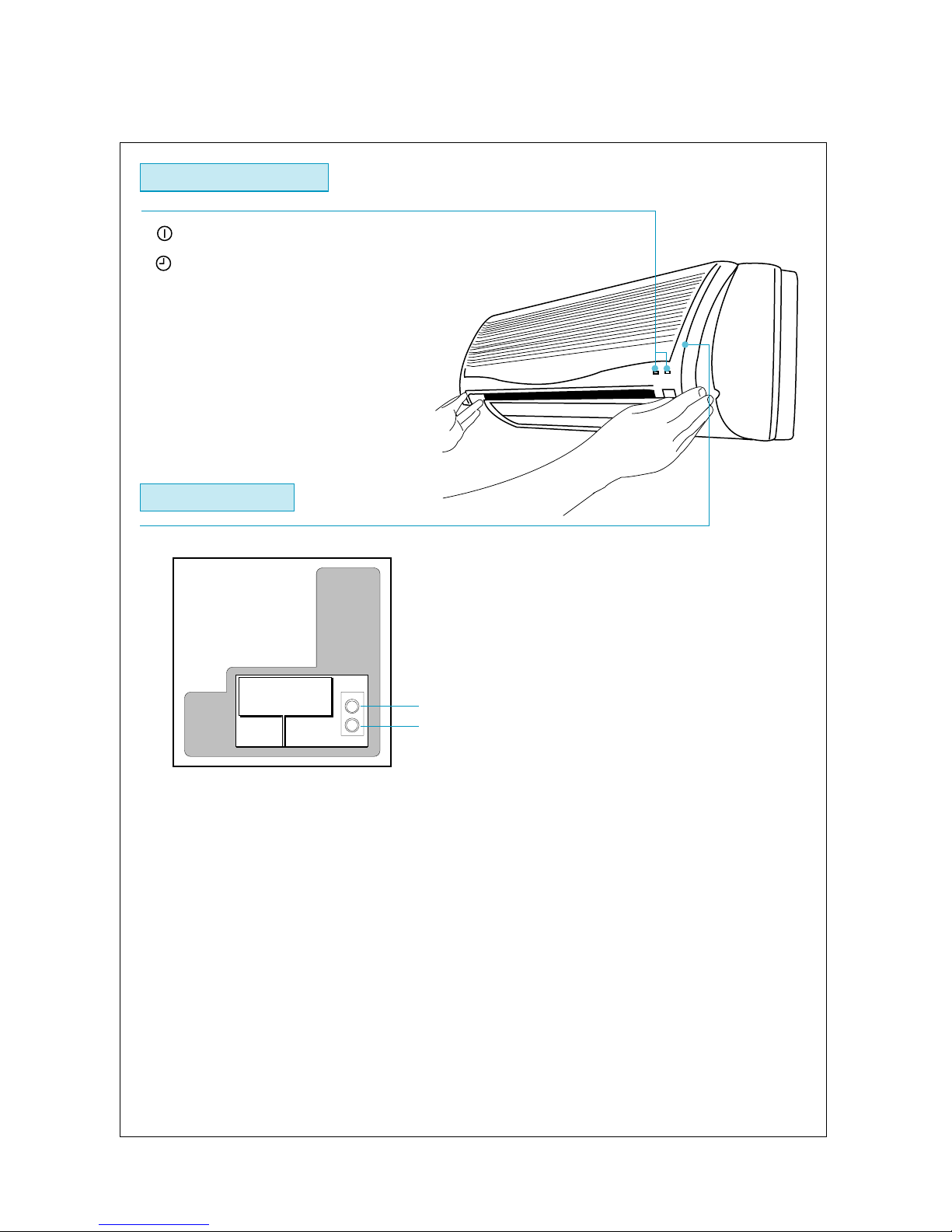
2) INDOOR UNIT DISPLAY AND SWITCH PANEL
.
(Green) : Lights during the operation.
.
(Orange) : Lights during timer mode.
Indoor Unit Display
Switches Panel
EMERG.
TEST
.
EMERG. button :
Can be used when the remote control is missed or inoperative.
.
TEST button :
Is only used by service men to test the unit operation.
.
For the usage of EMERG. and TEST buttons, refer to page 24.
“(8) Emergency and Test Operation.”
9
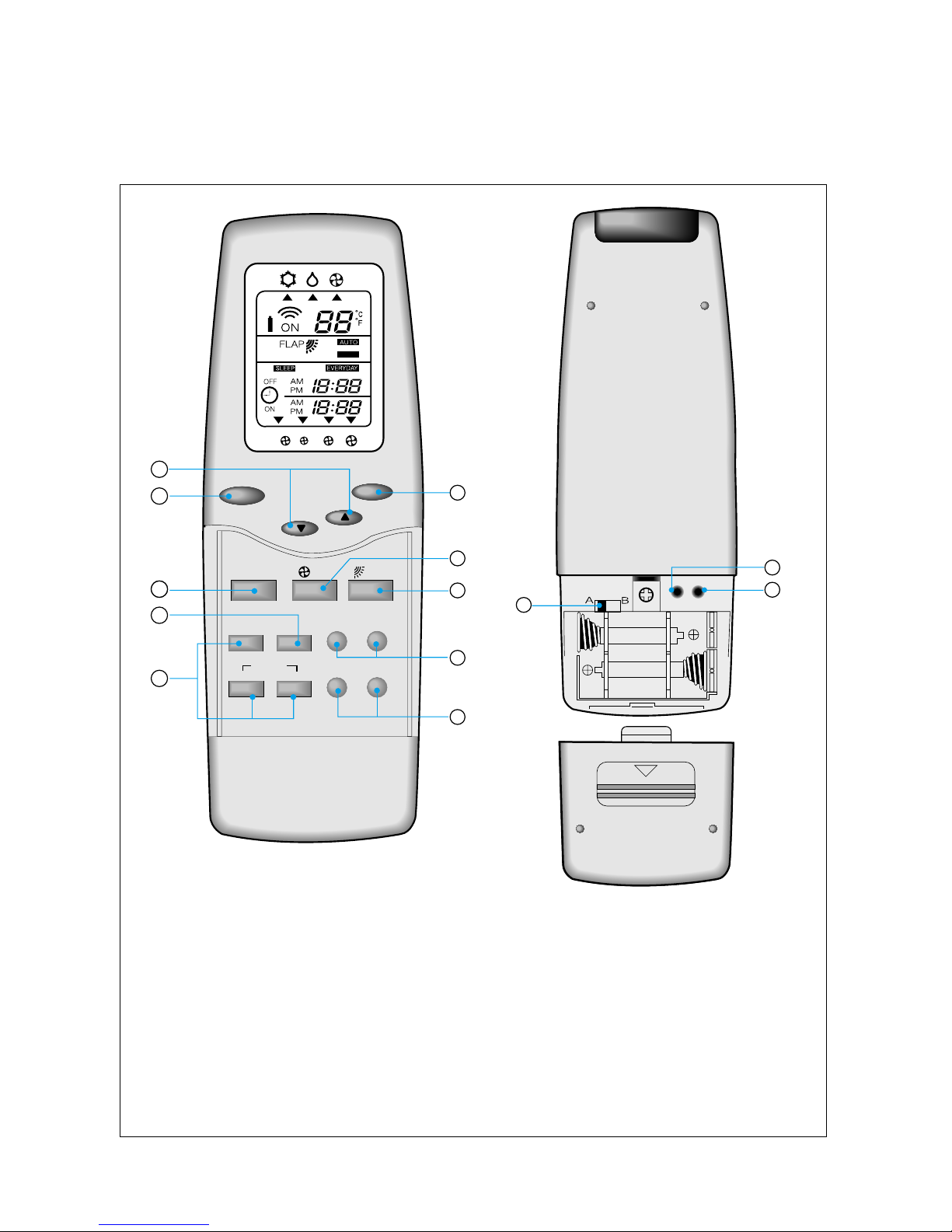
3) NAMES AND FUNCTIONS OF REMOTE CONTROLLER
• 42HWG007/009/012/018/024
HWG195C/225C/305C/455C/605C
RST TA
3
5
6
8
9
I / O
TEMP
.
SLEEP
MODE FLAP
CLOCK EVERYDAYHOUR MINUTE
SETTIMER
ON OFF
CANCEL
10
10
2
1
4
7
SWING
LR03(AM4)1.5V
LR03(AM4)1.5V
11
12
13
A
FAN
I/O BUTTON
TEMPERATURE SETTING BUTTONS
SLEEP TIMER BUTTON
OPERATION MODE SELECTING
BUTTON
FAN SPEED SELECTING BUTTON
FLAP CONTROL BUTTON
ON/OFF TIMER AND CURRENT
TIME BUTTONS
HOUR/MINUTE SETTING BUTTONS
SET AND CANCEL
BUTTONS
EVERYDAY TIMER BUTTON
CURRENT TIME ADJUSTING
BUTTON
RESET BUTTON
ADDRESS SWITCH
10
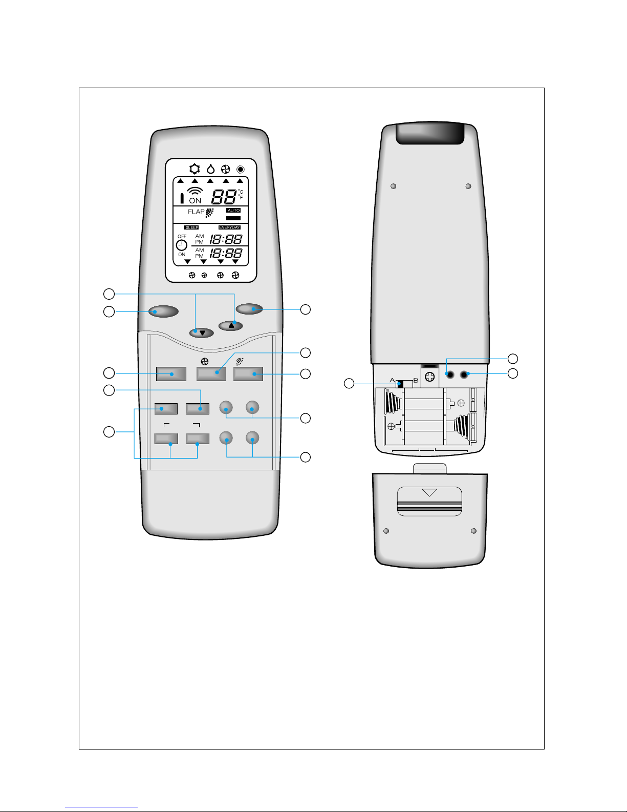
• 42HQG007/009/012/018/024 & HWG195H/225H/305H/455H/605H
I/O BUTTON
TEMPERATURE SETTING BUTTONS
SLEEP TIMER BUTTON
OPERATION MODE SELECTING
BUTTON
FAN SPEED SELECTING BUTTON
FLAP CONTROL BUTTON
ON/OFF TIMER AND CURRENT
TIME BUTTONS
HOUR/MINUTE SETTING BUTTONS
SET AND CANCEL
BUTTONS
EVERYDAY TIMER BUTTON
CURRENT TIME ADJUSTING
BUTTON
RESET BUTTON
ADDRESS SWITCH
RST TA
3
5
6
8
9
I / O
TEMP
.
SLEEP
MODE
CLOCK EVERYDAYHOUR MINUTE
SETTIMER
ON OFF
CANCEL
10
10
2
1
4
7
LR03(AM4)1.5V
LR03(AM4)1.5V
11
12
13
SWING
A
FLAPFAN
A
11
I/O BUTTON
Press this button to start operation. (A receiving beep is heard).
Press this button again to stop operation. (A receiving beep is heard).
When pressing the I/O button immediately after turning the unit off, the compressor
will not operate for 3 minutes to keep it from overloading.
TEMPERATURE SETTING BUTTON
Set the temperature to a desired room temperature, then unit will keep the tempera-ture to
the set temperature.
• In cooling mode, when the room temperature is higher than the setting, the com-
pressor is automatically turned on to provide a cooling effect. When the room temperature is lower than the setting, the compressor is automatically turned off to stop cooling
operation.
• In heating mode, when the room temperature is lower than the setting, the
compressor is automatically turned on to provide a heating effect. When the
room temperature is higher than the setting, the compressor is automatically
turned off to stop heating operation.
(42HQG007/009/012/018/024 & HWG195H/225H/305H/455H/605H)
However the indoor fan will run to circulate the indoor air even during turning off the
compressor.
SLEEP TIMER BUTTON
Press this button to set the sleep timer.
OPERATION MODE SELECTING BUTTON
Press this button to set the desired modes.
• DRY mode
In DRY mode, the microcomputer of the unit controls the indoor fan motor and makes
the outdoor unit automatically turn on and off according to the room tempera-
ture, and the room moisture will be removed more effectively.
• COOL mode
In COOL mode, the unit will run in normal cooling mode.
• FAN mode
In FAN mode, only the indoor fan will operate at the selected speed and circulate the room
air.
• HEAT mode (42HQG007/009/012/018/024 & HWG195H/225H/305H/455H/605H)
In HEAT mode, the unit will run in the normal heating mode.
• AUTO mode (42HQG007/009/012/018/024 & HWG195H/225H/305H/455H/605H)
In AUTO mode, the unit will operate automatically by selecting Cool or Heat mode and
Fan speed according to the room temperature.
12
FAN SPEED SELECTING BUTTON
Press this button to select the desired fan speed.
The indoor fan will operate at the selected fan speed. (AUTO, LOW, MED, HIGH)
When you select “AUTO”, the fan speed is controlled by microcomputer of the unit.
FLAP CONTROL BUTTON
Controls the discharge air flow direction up and down.
• In the beginning, the flaps open properly according to the operating mode.
• If you press this button, the flap will move stepwise and the position will be dis-
played.
• If you press this button again, the unit will operate at “SWING”. The flap will swing up
and down continuously at “SWING”.
ON/OFF TIMER AND CURRENT TIME BUTTONS
• Set the desired time for the unit control with these buttons.
• If you set ON and OFF time, the unit will be automatically turned on and off at the set
time.
• Press current time button when you want to know the current time, and the current
time is indicated.
SET AND CANCEL BUTTONS
Press SET button to reserve ON/OFF timer and if you want to cancel the reserved
time, use CANCEL button.
EVERYDAY TIMER BUTTON
Press this button at the reserved condition of the combined ON and OFF timer in
order to repeat the combined ON and OFF timer reservation everyday until the
reservation is canceled.
CURRENT TIME ADJUSTING BUTTON
Press this button to adjust the current time.
RESET BUTTON
Press this button when the remote control is not operating properly or after replacing
batteries.
ADDRESS SWITCH
If there are two indoor units in the same room, link one remote control with one indoor
unit, and link the other remote control with the other indoor unit.
HOUR/MINUTE SETTING BUTTONS
Adjust current time and ON/OFF timer with these buttons.
13
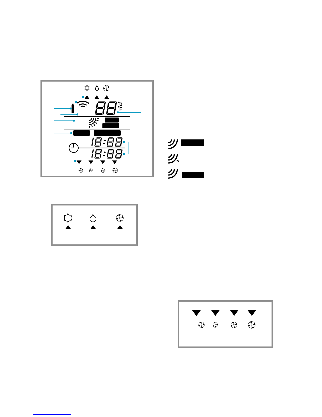
4) REMOTE CONTROLLER DISPLAY
• 42HWG007/009/012/018/024 & HWG195C/225C/305C/455C/605C
1
Indicates the selected operating mode.
2
Lights up when the signal from the remote
control is transmitted.
A receiving beep is heard from the unit.
3
Lights up when the batteries must be
replaced with new ones. When this mark
appears, replace the batteries within a week.
4
Lights up when the unit is operating.
5
Indicates the selected temperature.
6
Indicates flap modes
AUTO
SWING
Automatic position
User selected position
Swing up and down
7
Indicates the reserved status of SLEEP timer
or EVERYDAY timer.
8
Indicates the reserved time of ON timer
and OFF timer or the current time.
9
Indicates the selected fan speed.
OFF
OFF
ON
ON
AM
AM
PM
PM
AM
AM
PM
PM
FLAP
ON
AUTO
SLEEP
SLEEP
EVERYDAY
EVERYDAY
SWING
A
COOL DRY FAN
AUTO LOW MED HIGH
A

14
A
OFF
OFF
ON
ON
AM
AM
PM
PM
AM
AM
PM
PM
FLAP
FLAP
ON
AUTO
AUTO
SLEEP
SLEEP
EVERYDAY
EVERYDAY
SWING
SWING
A
• 42HQG007/009/012/018/024 & HWG195/225/305H/455H/605H
1
Indicates the selected operating mode.
2
Lights up when the signal from the remote
control is transmitted.
A receiving beep is heard from the unit.
3
Lights up when the batteries must be
replaced with new ones. When this mark
appears, replace the batteries within a week.
4
Lights up when the unit is operating.
COOL DRY FAN
A
HEAT
AUTOMATIC CHANGEOVER
5
Indicates the selected temperature.
6
Indicates flap modes
Automatic position
User selected position
Swing up and down
7
Indicates the reserved status of SLEEP timer
or EVERYDAY timer.
8
Indicates the reserved time of ON timer
and OFF timer or the current time.
9
Indicates the selected fan speed.
AUTO
SWING
AUTO LOW MED HIGH
A
15
5) DESCRIPTION OF FUNCTIONS
(1) Timer Mode
General features
– If user changes time of ON/OFF timer during timer function execution, the timer will be
changed according to the new set time.
– The other mode changes are enabled during timer function execution.
– The maximum timer range is twenty-four hours according to the remote controller.
– If user pushes the TEST or EMERG. button during timer function execution, timer function
will be canceled.
– If unit receives the timer function signal in Test or Emergency operation, these operations
will be canceled and timer function will be operated.
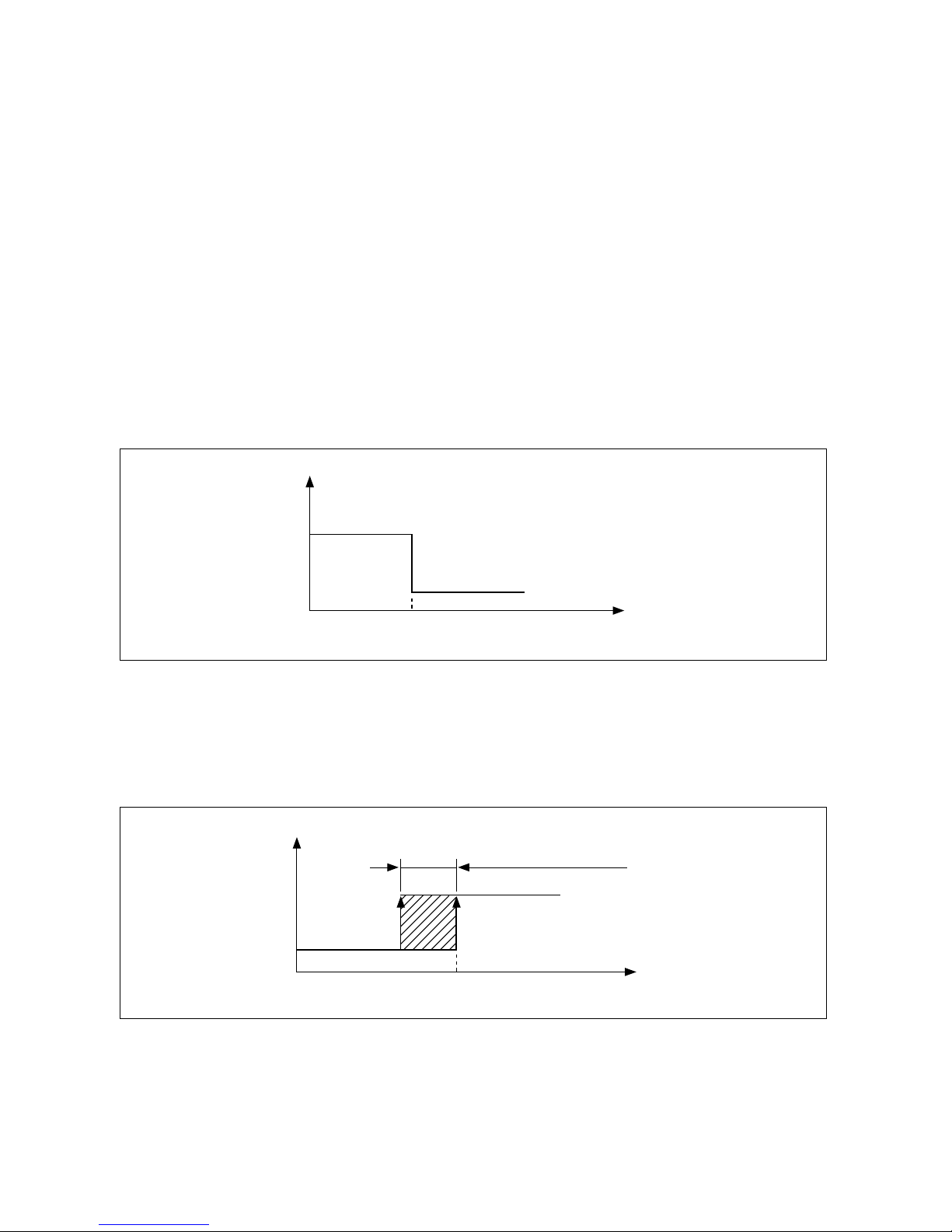
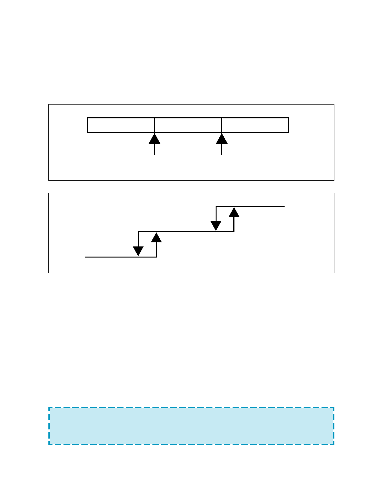
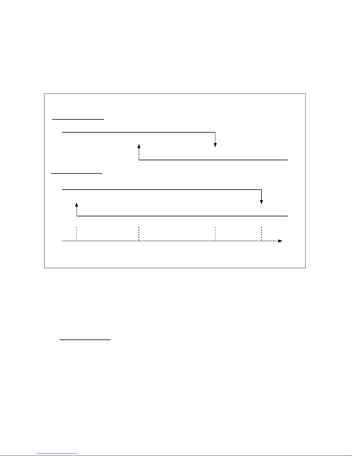
OFF-Timer
– If user sets time with OFF timer, the unit will stop at the set time.
– The unit will be turned off automatically when the set time of OFF timer is reached.
UNIT ON
UNIT OFF
HOURT.S.
T.S.=USER SET TIME
ON-Timer
– When the ON timer is set, unit monitors the room temperature before 1 hour from set time to
make the room as set condition at reserved set time.
– The actual on time of unit is decided at 0 to 40 minutes earlier than reserved on time accord-
ing to the room temperature and size.
UNIT OFF
HOUR
UNIT ON
T.S.
ACTUAL ON TIME(0~40MIN)
16
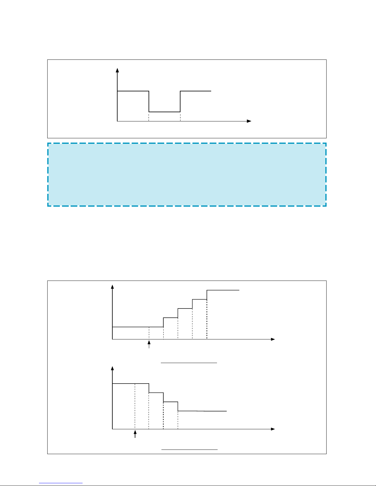
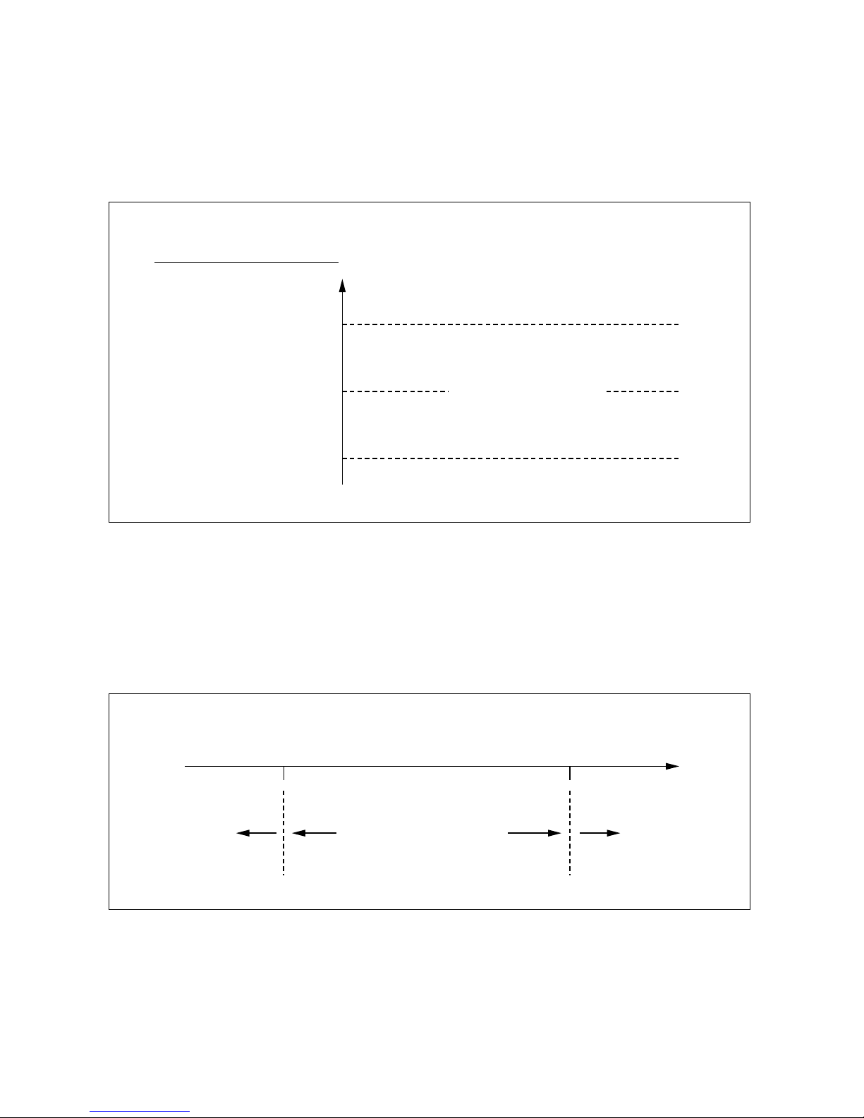
Combination of ON and OFF Timer
– If user sets time with ON/OFF timer, the unit will start and stop at the set time.
SLEEP-Timer
– When the SLEEP timer is set, the unit will control the setting temperature to avoid
overcooling in Cool operation or overheating in Heat operation.
– When the SLEEP timer is set, the luminosity of unit lamps will be dimly not to interrupt the
sleeping.
– The SLEEP timer can be combined with ON timer.
– Reserved time: 1hr, 2hr, 3hr, 7hr, 9hr
– Indoor fan will operate at low speed.
UNIT ON
UNIT OFF
HOUR
UNIT ON
ON TIMEOFF TIME
NOTE :
• The current time is not indicated during the reservation of ON/OFF timer.
• If user wants to know the current time, press the CLOCK button and the
current time will be displayed for 5 seconds.
• If user reserves the ON timer during operation, the unit will operate
continuously.
• In ON/OFF timer operation, the earlier setting compared to the current time
will operate first.
TIME (MIN.)
FOR COOLING MODE
SET TIME
30 70 110 150
SET
TEMP.
°C
+0.5°C
+0.5°C
+0.5°C
+0.5°C
TIME (MIN.)
FOR HEATING MODE
SET TIME
90 150
SET
TEMP.
°C
–1°C
–1°C
–1°C
30
17
EVERYDAY-Timer
– The EVERYDAY timer can be set in case of reserved condition of the combined ON and
OFF timer or the combined ON and SLEEP timer.
– If user sets time with EVERYDAY timer, the unit will repeat the combined ON and OFF timer
reservation everyday.
(2) Fan Speed
• User can select the fan speed of AUTO, LOW, MED and HIGH by the remote controller.
• If user selects 'AUTO' fan speed, the speed is automatically controlled according to the
room temperature. (See following figure).
(R.T-T.S)° C
LOW
MED
HIGH
0123
FAN SPEED IN AUTO COOL MODE
(T.S- R.T)° C
LOW
MED
HIGH
0 1 2 3 4 5
* R.T= ROOM TEMPERATURE
T. S= USER SET TEMPERATURE
FAN SPEED IN AUTO HEAT MODE
18
(3) Dry Mode
– This operation eliminates moisture effectively by operating the compressor, indoor and
outdoor fan motor intermittently, so that the room temperature is maintained at set
temperature.
– Determination of dry mode BLOCK based on Room temp. and Set temp.
(Set temp. : Ts)
1) Initial determination of dry mode BLOCK
CBA
Ts–2 Ts+1
2) Redetermination of dry mode BLOCK
C
B
A
Ts–2Ts–1 Ts+1 Ts+2
– Operating state according to the each BLOCK
1) BLOCK A
COMP & ODF : “ON”
IDF : operate at LOW speed
2) BLOCK B
COMP & ODF : repeat “ON” for 5 min. and “OFF” for 5 min.
IDF : operate at ULO speed
3) BLOCK C
COMP & ODF : “OFF”
IDF : operate at ULO speed
NOTE :
1. Unit determines again the dry mode BLOCK by sensing Room temp.
every 5 min.
2. 3 min. minimum operation of compressor is not applied.
19
(4) Automatic Operation
(42HQG007/009/012/018/024 & HWG195H/225H/305H/455H/605H)
– If the unit is set to ‘AUTO’ mode, the unit operates automatically by selecting COOL
or HEAT mode according to the room temperature to keep the room temperature
comfortable.
ROOM TEMPERATURE
T.S+1° C
T.S
T.S-1° C
COOLING MODE
HOLD CURRENT MODE
HEATING MODE
– When the room temperature is lower than 21°C or is higher than 29°C, the unit
operates Heating or Cooling operation regardless of the user set temperature.
This Automatic operation is not suitable for the application to the computer
room or some food/wine stock storage
21° C
COOL/HEAT TRANSITION
HEATING
ONLY
COOLING
ONLY
SENSED
ROOM TEMP.
29° C
20
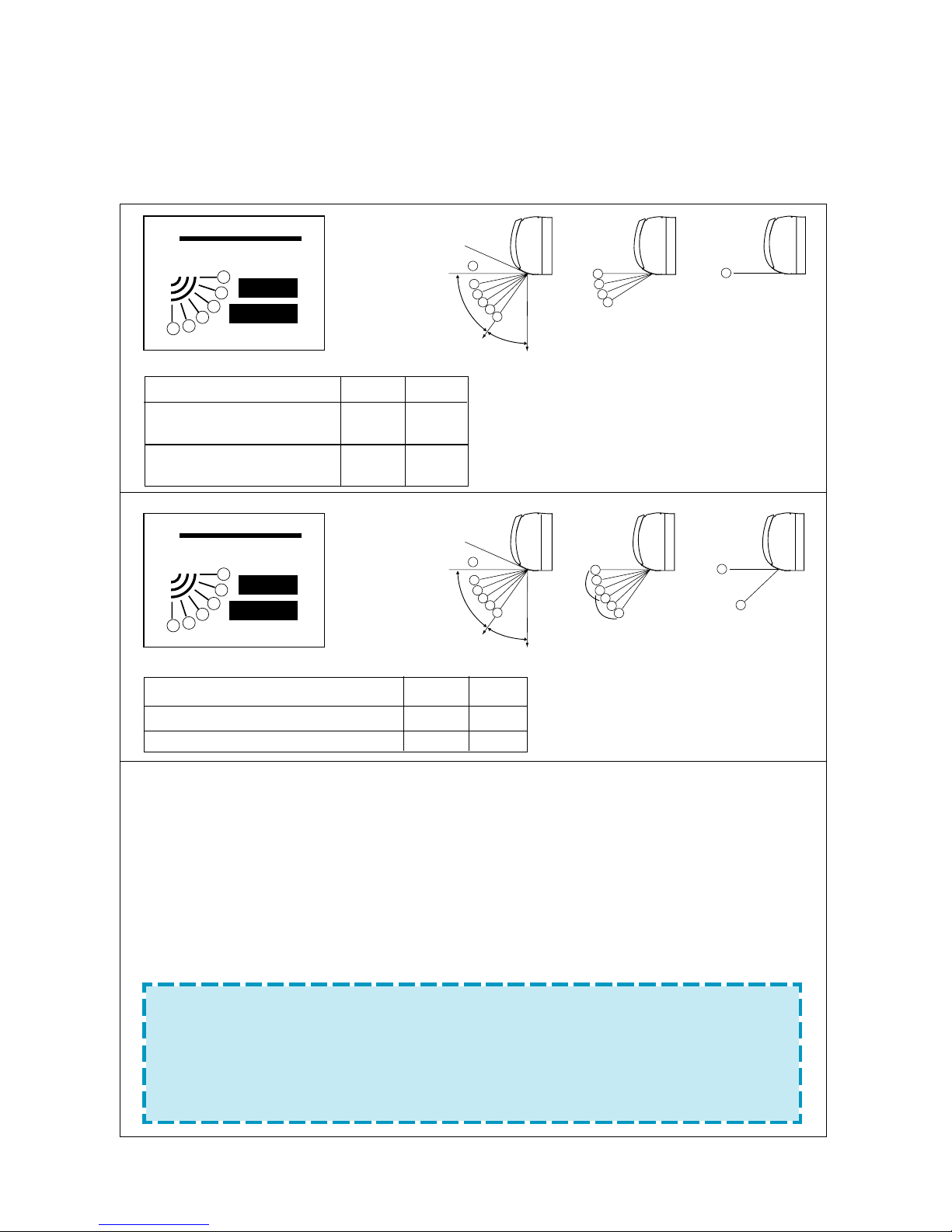
(5) Discharge Air Louver Control
Up and Down Control
The air discharge direction can be controlled to swing up and down and can be fixed at
preferred position or automatic position by the remote control.
• If you select the Flap position using the FLAP button in the remote control, the flap in
the unit will move to that position automatically. Once you select the position, the unit
remembers that position and whenever you turn on the unit, the flap will be positioned
to that position.
• If you select SWING, the flap will swing up and down. In the COOL, DRY and FAN
mode, the flap will swing in the cool range. In the HEAT mode, the flap will swing in the
heat range.
• If you select AUTO, the flap will position itself to the preset position according to the
operation mode.
NOTE
• Always use the remote control to adjust the flap position, otherwise it may cause
abnormal operation. Please turn off the unit and turn it on again when you manually adjust the flap out of range.
• The unit can have maximum capacity when the flap is located at position
.
6
1
2
3
4
5
6
3
4
5
6
CLOSE
A
B
Fixed
Swing Range
Auto Position
Cooling Only Model
AUTO
SWING
FLAP
6
5
4
3
2
1
Remote control
6
3
4
5
6
Fixed Swing Range Auto Position
Heat Pump Model
2
1
COOL
HEAT
2
COOL
HEAT
1
2
3
4
5
6
CLOSE
A
B
AUTO
SWING
FLAP
6
5
4
3
2
1
Remote control
MODEL A B
42HWG007/009/012
HWG195C/225C/305C 54° 36°
42HWG018/024
HWG455C/605C 66° 24°
MODEL A B
42HQG007/009/012, HWG195H/225H/305H 54° 36°
42HQG018/024, HWG455H/605H 66° 24°
21
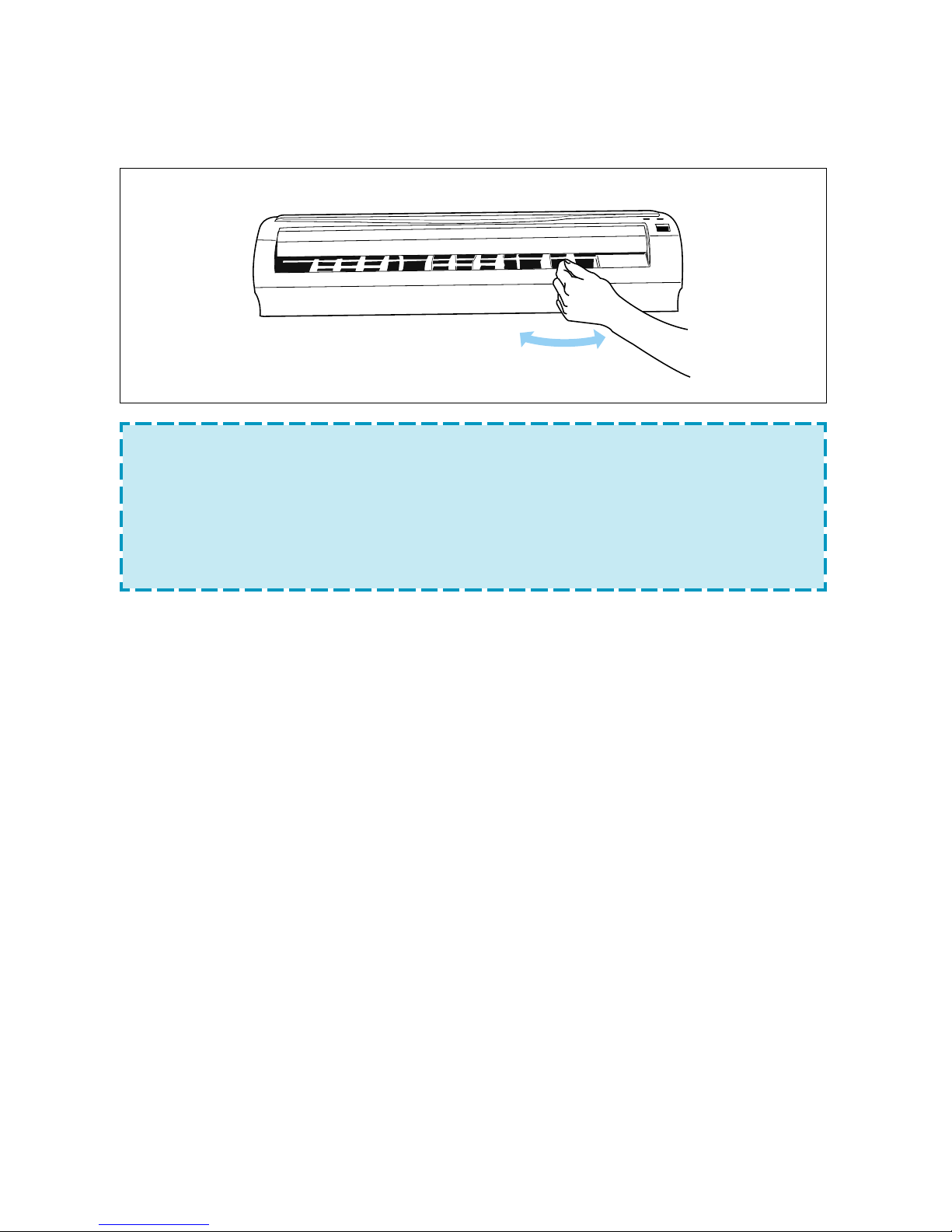
Left and Right Control
If you want to adjust the direction of the discharge air to left or right, adjust the vertical
louver with the handle after opening the flap.
HANDLE
NOTE
•
Please do not fix the flap at position for a long time, as this position minimizes air
circulation resulting in uneven room temperature.
• Please avoid the discharge air being directed towards the occupants for a long period
of time.
• Do not adjust the flap by the hand during SWING operation because it may damage
the air swing function.
(6) Unit Protection Devices
3 min. Time Delay and 3 min. minimum operation time of compressor
– In normal operation, there is a time delay of three minutes (42HQG024/HWG605H : 5
minutes during heating mode) between compressor turning off and turning back on including initial power up.
– After compressor turns on, it will operate for 3 minutes independent of temperature condi-
tion.
Time Delay When changing the operation mode
– The unit operates immediately when changing mode from ON to OFF or from OFF to ON,
or indoor fan speed without the change of operation mode.
– The unit operates after 10-second time delay when changing operating mode.
– The unit operates after 3-second time delay when changing the set temp. without the
change of operation mode.
Frost Prevention of Indoor Unit.
– When the unit operates at low ambient temperature, frost may appear on the evapo-
rator. When the indoor coil temperature is less than 0ºC for 10 minutes of continuous compressor operation from the start, microcomputer of the unit stops the compressor to protect the unit from the frost.
– The system performs this function only in COOL and DRY mode.
– The control procedure for indoor coil freeze protection.
1) The compressor and outdoor fan turn off.
2) Indoor fan operates according to user set speed.
3) The normal operation returns when the indoor coil temperature is greater than or equal
to 7ºC.
22
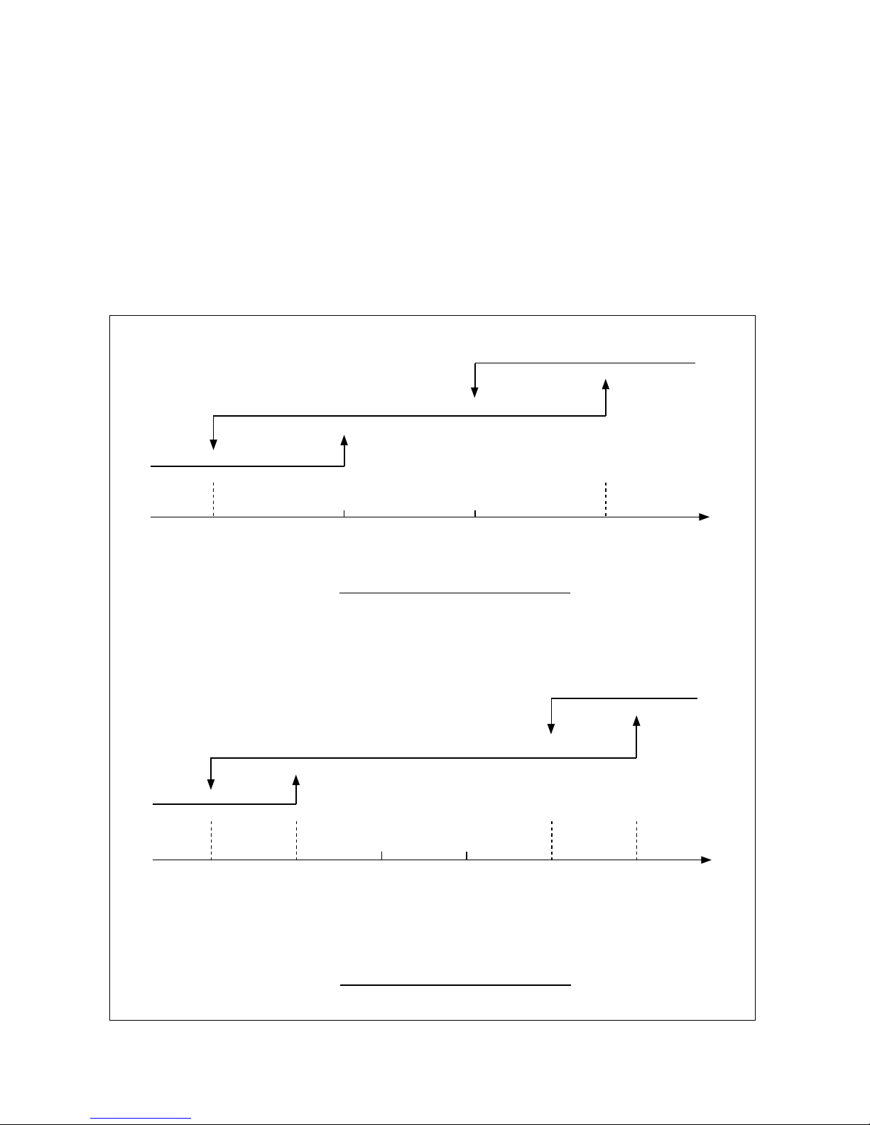
Indoor Coil High Temperature Protection
– The system performs this function only in HEAT mode.
– If the indoor coil temperature is greater than or equal to 57°C, the outdoor fan turns off and
does not turn on until the indoor coil temperature is less than or equal to 49°C.
– If the indoor coil temperature is greater than or equal to 62°C, the compressor turns off
until the indoor coil temperature is less than or equal to 42°C. The 3 min. time delay of
compressor is applied in this case.
INDOOR COIL TEMP.
ON
42° C 49° C 57° C 62° C
ON
OFF
OFF
OUTDOOR FAN
COMPRESSOR
Defrost
– In HEAT mode, outdoor coil may be frosted, which cause decrease of the unit perfor-
mance. Therefore the microcomputer of the unit turns on or off the compressor to remove the frost.
– The defrost operation is performed as follows:
• Defrost initiation
1) On the basis of the demand condition considering the difference between indoor
coil temperature and indoor room temperature, controller decides defrost initiation
after satisfying two steps of preceding condition.

23
2) Preceding condition is
a) The first step is “the accumulated compressor on time is greater than 30
minutes.”
b) Second step is the one of below two
-The first condition ; If Real-Delta>Defrost-Delta for 60 continuous seconds and
the following conditions are all true then defrost initiates.
)The outdoor coil temperature<-2°C
)The compressor has been on continuously for 15 minutes.
OR
-The second condition ; If the outdoor coil temperature is less than -20°C and
the following conditions are all true then defrost initiates.
)The outdoor fan has been on continuously for 60 seconds.
)The compressor has been on continuously for 3 minutes.
•
Defrost mode
The normal system operations are stopped and the system operates as follows.
a) The indoor fan, outdoor fan will be de-energized.
b) The compressor and R.V.S. will be energized.
•
Defrost termination
The defrost cycle will terminate in one of the following cases.
a) The outdoor coil temperature is greater than or equal to +25°C.
b) 10 minutes after the start of defrost cycle.
•
Auto refresh
During normal heating operation, if the unit becomes OFF mode condition, then
defrost mode will be performed at the OFF mode state of louver and display when
the second step of preceding conditions is satisfied regardless of first step.
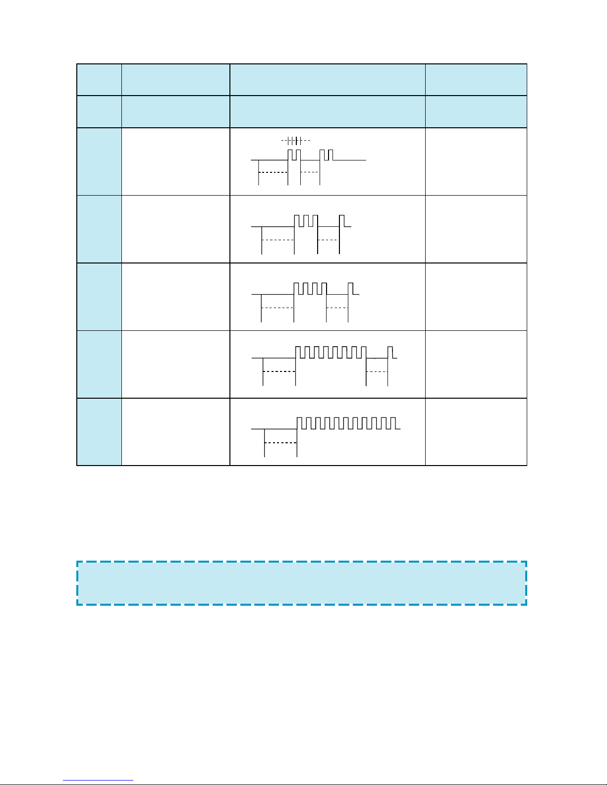
Self-Diagnostic Function
The control will contain diagnostic test to verify the integrity of the system.
Once a malfunction is detected, the diagnostic control section will force the system mode
to OFF for 3 minutes. After the OFF delay, system mode is released and allowed to return
to its normal state. The system will be allowed to restart on its own. The diagnostic control
section will allow the system to fail 5 consecutive times before shutting down the system.
The lamp is scanned every half second and the error codes are displayed by the
flashing frequency of lamp. The error codes are displayed during SHUT-OFF (3
minutes off and after the 5th retry failure) as follows.
24
NOTE :
If more than two errors occur, the highest item are displayed.
If the highest item is cleared, the next item codes are displayed.
NO ERROR DISPLAY ALLOWED
(RANK)
CONTENTS PATTERN MODES
1 MICOM MEMORY NOTHING SYSTEM RESET
2 ROOM AIR FAN ONLY
THERMISTOR MODE
MALFUNCTION
3 INDOOR COIL FAN ONLY
THERMISTOR MODE
MALFUNCTION
4 OUTDOOR COIL FAN ONLY
THERMISTOR MODE
MALFUNCTION
5 INDOOR FAN
MOTOR
MALFUNCTION
6 THERMISTOR ALL
WRONG WIRING MODE
(ONLY IN TEST
MODE)
3 sec
3 sec
0.5 sec (2 times)
3 sec
3 sec
0.5 sec (3 times)
0.5 sec (4 times)
3 sec
3 sec
3 sec3 sec
0.5 sec (8 times)
3 sec
0.5 sec (continue)
25
Auto restart Mode
– When the power failure is happened during the system operating, the micro will memo-
rize the operation mode and the unit operates automatically according to the previous
operating mode after the power is recovered.
– Whenever the unit receives remote signal, the micom will memorize the following opera-
tion
• Power ON/OFF
• Operation mode
• Temperature setpoint
• Louver position
• Fan speed
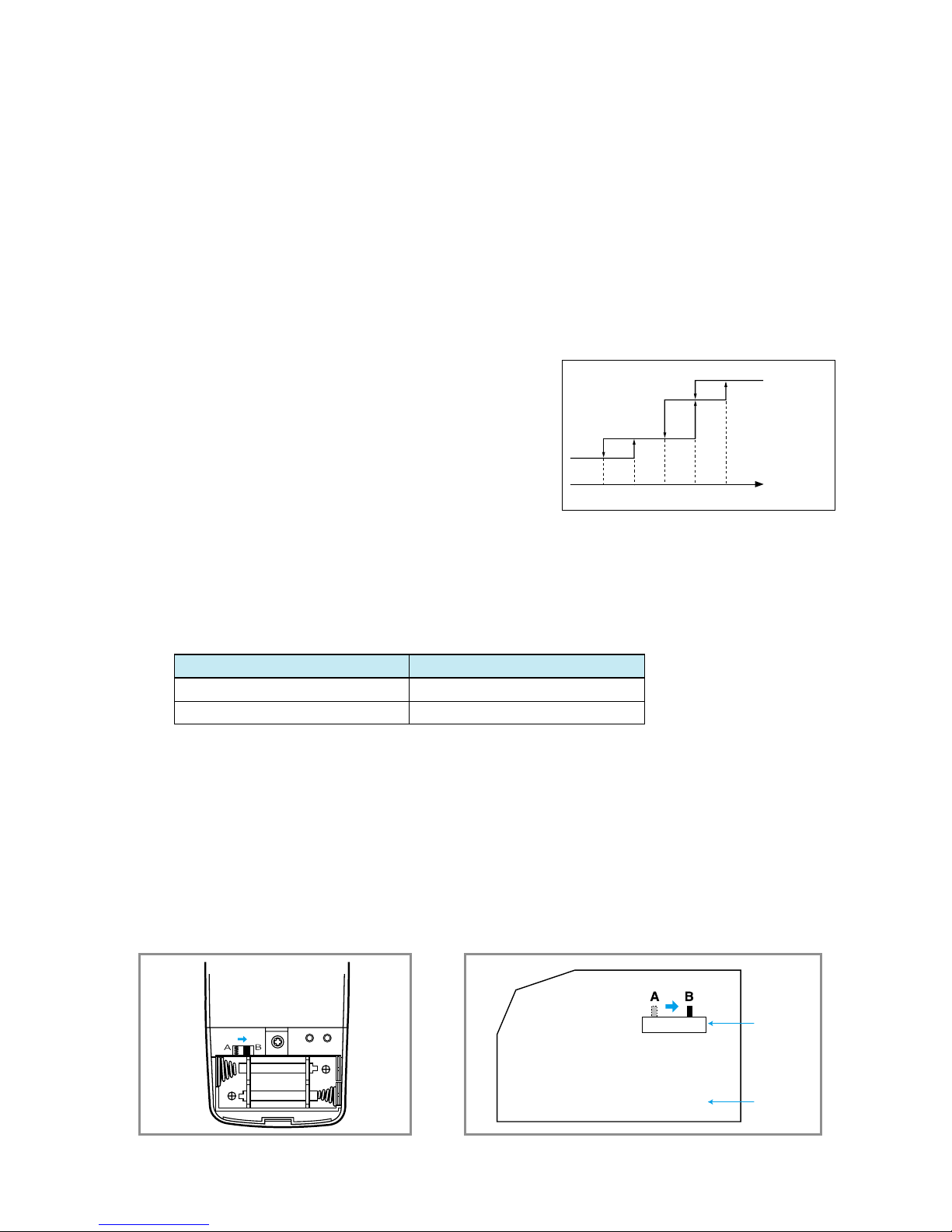
Cold draft function
– The system performs this function only in HEAT mode.
– If the indoor coil temperature is lower than
a certain level, then indoor fan motor runs at slow
speed regardless of user setting speed.
1) When the compressor stops,
Indoor fan moter runs at monitoring speed only.
2) When the compressor runs,
Indoor fan motor runs as follows.
(7) Address configuration
– According to input of selecting address configuration, this function configures custom
code of transmitted remote signal and processes it as input.
– Processable custom codes are displayed as follows.
Address configuration Processable custom code
A DCCA
B DCCB
–
If user wants to use “B” address, adjust the slide switch to “B” in control PCB and
remote.
ADDRESS
PCB
RST TA
LR03(AM4)1.5V
LR03(AM4)1.5V
•
Remote control
• Remove the lid of battery case.
• Assign the address switch of one remote
control as B.
• Press the RST button with a sharp object.
•
Indoor unit
• Turn off the unit and pull out the power plug.
• Remove the front panel, terminal block cover and
frame grille.
• Pull out the PCB.
• Assign the address switch of one indoor unit as B.
Indoor Coil
temperature(
ϒC
)
0
ϒC
-3
ϒC
30ϒC37ϒC43
ϒC
OFF
Monitoring Speed
Setted Speed
Low
26
(9) Emergency and T est Operation.
Emergency operation
– When the remote control is lost, damaged or the battery is discharged, the
Emergency operation can be able to run the unit.
– lf user wants Emergency operation, push the EMERG. button on the T/B cover of
the indoor unit.
– The unit is operated automatically by selecting Cooling or Heating Mode according
to the room temperature.
– lf user wants to stop the Emergency operation, push the EMERG. button again or
operate remote control.
– The setting conditions of Emergency operation are as follows.
• Operation mode :
AUTO (42HQG007/009/012/018/024, HWG195H/225H/305H/455H/605H)
COOL (42HWG007/009/012/018/024, HWG195C/225C/305C/455C/605C)
• Preset temperature:
25ºC (42HQG007/009/012/018/024, HWG195H/225H/305H/455H/605H)
24C (42HWG007/009/012/018/024, HWG195C/225C/305C/455C/605C)
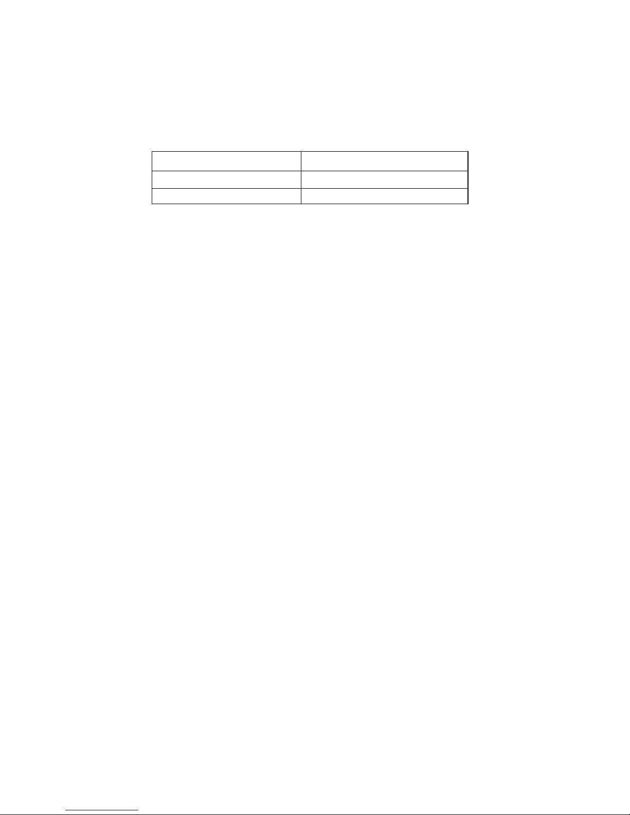
(8) DST Interface
–
According to input of selecting address configuration of indoor unit PCB, the one of
below functions is assigned.
– The applicable connector for these functions is CN18 of indoor unit PCB.
DST Interface
1) The DST(Dealer Service Tool) is an application program used to verify a defec-
tive control board in Air Conditioner
2) It can also be used to diagnose the fault before the board replacement.
3) To use DST function, first of all, following preparations are required.
– DST interface converter
– G-DST interconnection wire
– IBM PC 386DX-33 processor with MS Windows OS 3.1
( Minimum system requirement )
4) If there are any problems or questions relating to the operation or installation of
the DST please consult the ‘Installation Guide and User’s Manual’
Address configuration Functions
A DST Interface available
B DST Interface not available
 Loading...