


38VMH192
Carrier 38VMH192, 38VMH120, 38VMH216, 38VMH240, 38VMH264 Installation And Maintenance Instructions Manual
...
38VMH072-432
Outdoor Unit for
Variable Refrigerant Flow (VRF) Heat Pump Systems
Installation and Maintenance Instructions
CONTENTS
Page
SAFETY CONSIDERATIONS . . . . . . . . . . . . . . . . . . . 1
GENERAL . . . . . . . . . . . . . . . . . . . . . . . . . . . . . . . . . . . 2
INSTALLATION. . . . . . . . . . . . . . . . . . . . . . . . . . . . . . . 9
Step 1 — Unpack and Inspect Units . . . . . . . . . . . . 9
• PROTECTING UNITS FROM DAMAGE
• PREPARING JOBSITE FOR UNIT INSTALLATION
• IDENTIFYING AND PREPARING UNITS
Step 2 — Position the Unit . . . . . . . . . . . . . . . . . . . 10
• HANDLING THE UNIT
• CONCRETE BASE REQUIREMENTS
• OUTDOOR UNIT PLACEMENT
• SPACE REQUIRED FOR INSTALLATION AND
MAINTENANCE
• SNOW GUARD INSTALLATION
• ACCESSING REFRIGERANT AND ELECTRICAL
CONNECTIONS
Step 3 — Connect Refrigerant Piping . . . . . . . . . . 12
• REFRIGERANT PIPING CONNECTIONS
• REFRIGERATION PIPING MEASUREMENTS
• CONNECTING THE OUTDOOR UNITS
Step 4 — Pressure and Vacuum Test System . . 19
Step 5 — Adjust Refrigerant Charge . . . . . . . . . . . . 19
Step 6 — Complete Electrical Connections. . . . . . . 19
• POWER SUPPLY
• OPENING AND CLOSING THE ELECTRICAL
COMPONENT BOX
• POWER WIRING
• WIRING THE COMMUNICATION TERMINAL
BLOCK
• COMMUNICATION CABLE
• COMMUNICATION WIRING
• OPTION/EXTENSIONS OF COMMUNICATION
WIRING
START-UP . . . . . . . . . . . . . . . . . . . . . . . . . . . . . . . 23, 24
Trial Run. . . . . . . . . . . . . . . . . . . . . . . . . . . . . . . . . . . . 23
Unit Settings . . . . . . . . . . . . . . . . . . . . . . . . . . . . . . . . 24
Advanced Settings . . . . . . . . . . . . . . . . . . . . . . . . . . . 25
Snow-Blowing Functions. . . . . . . . . . . . . . . . . . . . . . 25
Pre-Start Check . . . . . . . . . . . . . . . . . . . . . . . . . . . . . 25
MAINTENANCE . . . . . . . . . . . . . . . . . . . . . . . . . . . 26
SAFETY CONSIDERATIONS
Improper installation, adjustment, alteration, service,
maintenance, or use can cause explosion, fire, electrical shock,
or other conditions; which may cause death, personal injury or
property damage. The qualified installer or agency must use
factory-authorized kits or accessories when modifying this
product.
Follow all safety codes. Wear safety glasses, protective
clothing, and work gloves. Use quenching cloth for brazing
operations. Have fire extinguisher available. Read these
instructions thoroughly and follow all warnings or cautions
included in literature and attached to the unit. Consult local
building codes and the current editions of the National
Electrical Code (NEC) ANSI/NFPA (American National
Standards Institute/National Fire Protection Association) 70. In
Canada, refer to the current editions of the Canadian Electrical
Code CSA (Canadian Standards Association) C22.1.
Understand the signal words — DANGER, WARNING,
and CAUTION. DANGER identifies the most serious hazards,
which will result in severe personal injury or death.
WARNING signifies hazards that could result in personal
injury or death. CAUTION is used to identify unsafe practices,
which would result in minor personal injury or product and
property damage.
Recognize safety information. This is the safety-alert
symbol ( ). When this symbol is displayed on the unit and in
instructions or manuals, be alert to the potential for personal
injury. Installing, starting up, and servicing equipment can be
hazardous due to system pressure, electrical components, and
equipment location.
WARNING
Electrical shock can cause personal injury and death. Shut
off all power to this equipment during installation. There
may be more than one disconnect switch. Tag all
disconnect locations to alert others not to restore power
until work is completed.
Manufacturer reserves the right to discontinue, or change at any time, specifications or desi gns without notice and wit hout incurring obligations.
Catalog No. 18-38VMH001-01 Printed in U.S.A. Form 38VMH-3SI Pg 1 10-18 Replaces: 38VMH-1SI
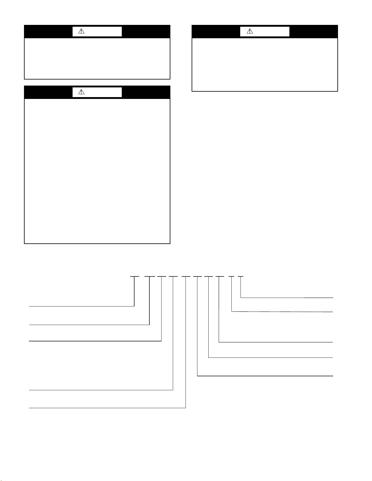
WARNING
Equipment Type
38 —
Outdoor Unit
Voltage (V-Ph-Hz)
VM — VRF
Product Type
5 — 208/230-3-60
6 — 460-3-60
Blank
Model Number Modifier
AA — Revision Number — Revision Number
Capacity (Btuh)
072 — 72,000
096 — 96,000
120 — 120,000
144 — 144,000
168 — 168,000
192 — 192,000
System Type
H — Heat Pump
38
VM
Cabinet Type
S — Standard
Variations
D — Domestic
Packaging
1 — USA & Canada
216 — 216,000
240 — 240,000
264 — 264,000
288 — 288,000
312 — 312,000
336 — 336,000
360 — 360,000
384 — 384,000
408 — 408,000
432 — 432,000
A 072 H D S 5 - 1
CAUTION
When installing the equipment in a small space, provide
adequate measures to avoid refrigerant concentration
exceeding safety limits due to refrigerant leak. In case of
refrigerant leak during installation, ventilate the space
immediately. Failure to follow this procedure may lead to
personal injury.
WARNING
DO NOT USE TORCH to remove any component. System
contains oil and refrigerant under pressure.
To remove a component, wear protective gloves and
goggles and proceed as follows:
a. Shut off electrical power to unit.
b. Recover refrigerant to relieve all pressure from
system using both high-pressure and low pressure
ports.
c. Traces of vapor should be displaced with nitrogen
and the work area should be well ventilated.
Refrigerant in contact with an open flame produces
toxic gases.
d. Cut component connection tubing with tubing cutter
and remove component from unit. Use a pan to catch
any oil that may come out of the lines and as a gage
for how much oil to add to the system.
e. Carefully unsweat remaining tubing stubs when
necessary. Oil can ignite when exposed to torch
flame.
Failure to follow these procedures may result in personal
injury or death.
DO NOT re-use compressor oil or any oil that has been
exposed to the atmosphere. Dispose of oil per local codes
and regulations. DO NOT leave refrigerant system open to
air any longer than the actual time required to service the
equipment. Seal circuits being serviced and charge with
dry nitrogen to prevent oil contamination when timely
repairs cannot be completed. Failure to follow these
procedures may result in damage to equipment.
GENERAL
The VRF (variable refrigerant flow) Heat Pump system
offers a variety of indoor unit types and sizes, ranging from 0.5
to 8 tons. The 38VMA Heat Pump outdoor units are available
in four capacities, 6, 8, 10, and 12 tons. Units can be combined
to accommodate larger capacity requirements. The system has
capability to operate between 50% and 135% connected
capacity, allowing the system to be tailored to the needs of the
customer and the application.
The equipment is initially protected under the
manufacturer’s standard warranty; however, the warranty is
provided under the condition that the steps outlined in this
manual for initial inspection, proper installation, regular
periodic maintenance, and everyday operation of the unit be
followed in detail. This manual should be fully reviewed in
advance before initial installation, start-up, and maintenance.
Contact your local sales representative or the factory with any
questions BEFORE proceeding.
See Fig. 1 for model number nomenclature. Table 1 shows
components that may or may not be used for a particular
installation. T able 2 lists physical data for each unit size. Tables
3-6 list physical data for combination units. Figure 2 shows
unit dimensions.
Fig. 1 —Nomenclature
2
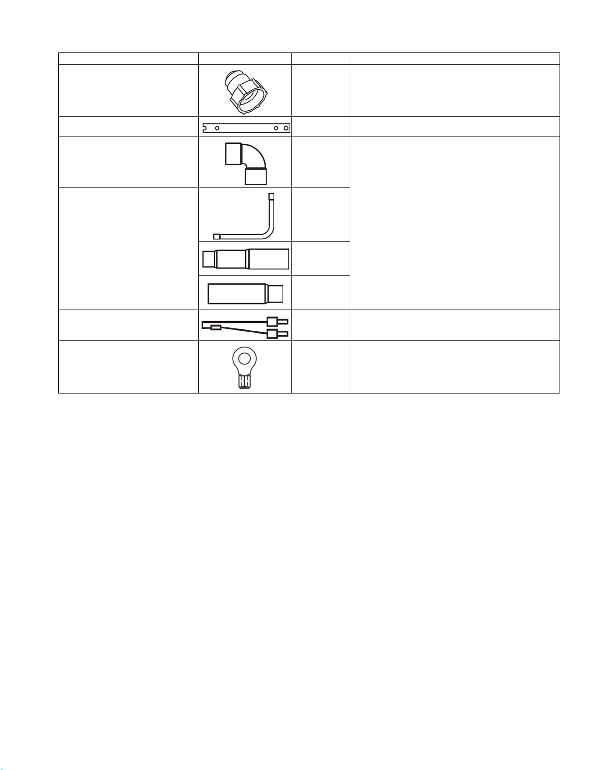
Table 1 — Components Shipped with Unit
NAME SHAPE QUANTITY FUNCTION
Seal plug 8 For maintenance
Simple wrench 1 For removing the side plate screws
2
(Sizes 072, 096,
90 degree elbow
and 120)
1
(Size 144)
3
Connective pipe accessories
Network Resistor 2 Enhances stability of communication
Ring terminal 4 For connecting the power wire
1
(Sizes 072, 096,
and 120 only)
1
For outdoor unit and refrigerant pipe connection
3
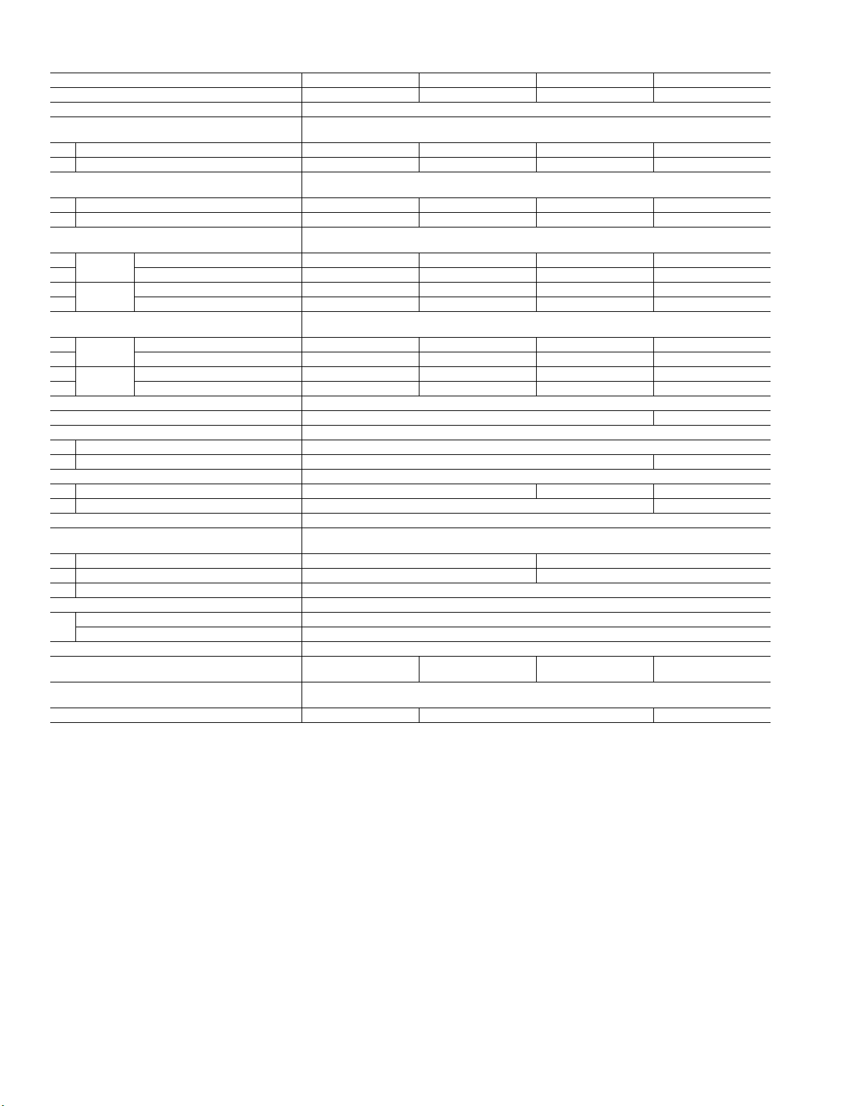
Table 2 — 38VMH Physical Data
UNIT 072 096 120 144
NOMINAL TONS (Ton) 6 8 10 12
POWER SUPPLY (V-Ph-Hz)* 208/230-3-60 / 460-3-60
COOLING CAPACITY WITH NON-DUCTED
INDOOR UNITS†
Nominal (kBtu/h) 72.0 90.0 117.6 142.8
Rated (kBtu/h) 69.0 92.0 112.0 136.0
HEATING CAPACITY WITH NON-DUCTED
INDOOR UNITS†
Nominal (kBtu/h) 80.0 108.0 126.0 160.0
Rated (kBtu/h) 77.0 103.0 120.0 150.0
ELECTRICAL CHARACTERISTICS WITH
NON-DUCTED INDOOR UNITS
Cooling
Heating
ELECTRICAL CHARACTERISTICS WITH
DUCTED INDOOR UNITS
Cooling
Heating
UNIT DIMENSIONS (W x H x D) (in.) 52-
UNIT NET WEIGHT (lb)** 659 780
COMPRESSOR
Type Hermetic Scroll Compressor (Inverter Driven)
Motor Output (kW) 23.25 22.9+13.8
FAN UNIT
Air Volume (cfm) 7650 8250 8830
Motor Output (W) 270 (x2) 340+300
REFRIGERANT SHIPPING CHARGE (lb)†† 37.5
REFRIGERANT CONNECTING PORT
DIAMETER
Gas Side (in.)
Liquid Side (in.)
Balance Pipe (in.)
OPERATION TEMPERATURE RANGE
Cooling (F db) 5~125
Heating (F wb) -5~64
MAX ESP (in. wg) 0.08
MAX NUMBER OF CONNECTED INDOOR
UNITS
MAXIMUM CAPACITY OF COMBINED
INDOOR UNITS ***
SOUND PRESSURE LEVEL (db(A))††† 62.5 63.0 65.5
LEGEND
COP — Coefficient of Performance
db — Dry Bulb
EER — Energy Efficiency Ratio
ESP — External Static Pressure
wb — Wet Bulb
* The source of voltage must not fluctuate more than ± 10%.
† Rated conditions:
Cooling: Indoor air temperature 80
Outdoor air temperature 95
Heating: 70
bulb / 43
Power Consumption (kW) 4.10 6.20 8.80 12.10
EER (Btu/W) 14.10 13.20 11.70 10.60
Power Consumption (kW) 4.50 7.20 9.00 12.10
COP (W/W) 4.29 3.82 3.60 3.40
Power Consumption (kW) 5.10 7.50 9.60 12.30
EER (Btu/W) 12.80 11.80 11.20 10.60
Power Consumption (kW) 5.60 8.00 9.80 12.60
COP (W/W) 3.85 3.63 3.45 3.35
3
/4 x 64-3/8 x 31-1/
7
/
8
3
/
8
1
/
4
8
1-1/
1
13 16 20 26
50% to 135%
** Units are shown as 230V [460V]. If there are no brackets,
units are the same for 230V and 460V.
†† The amount does not consider extra piping length. Refrigerant
must be added on site in accordance with the actual piping length.
*** In case the diversity exceeds 135%, the type of indoor unit is
limited and the maximum number of indoor unit is reduced.
††† These values, measured in anechoic chamber, at a point 1 m in
front of the unit at a height of 1.4 m. During actual operation,
these values are normally somewhat higher as a result of ambient
° F dry bulb / 67° F wet bulb,
° F dry bulb, Outdoor air temperature 47° F dry
° F wet bulb.
° F dry bulb.
conditions.
8
/
2
4
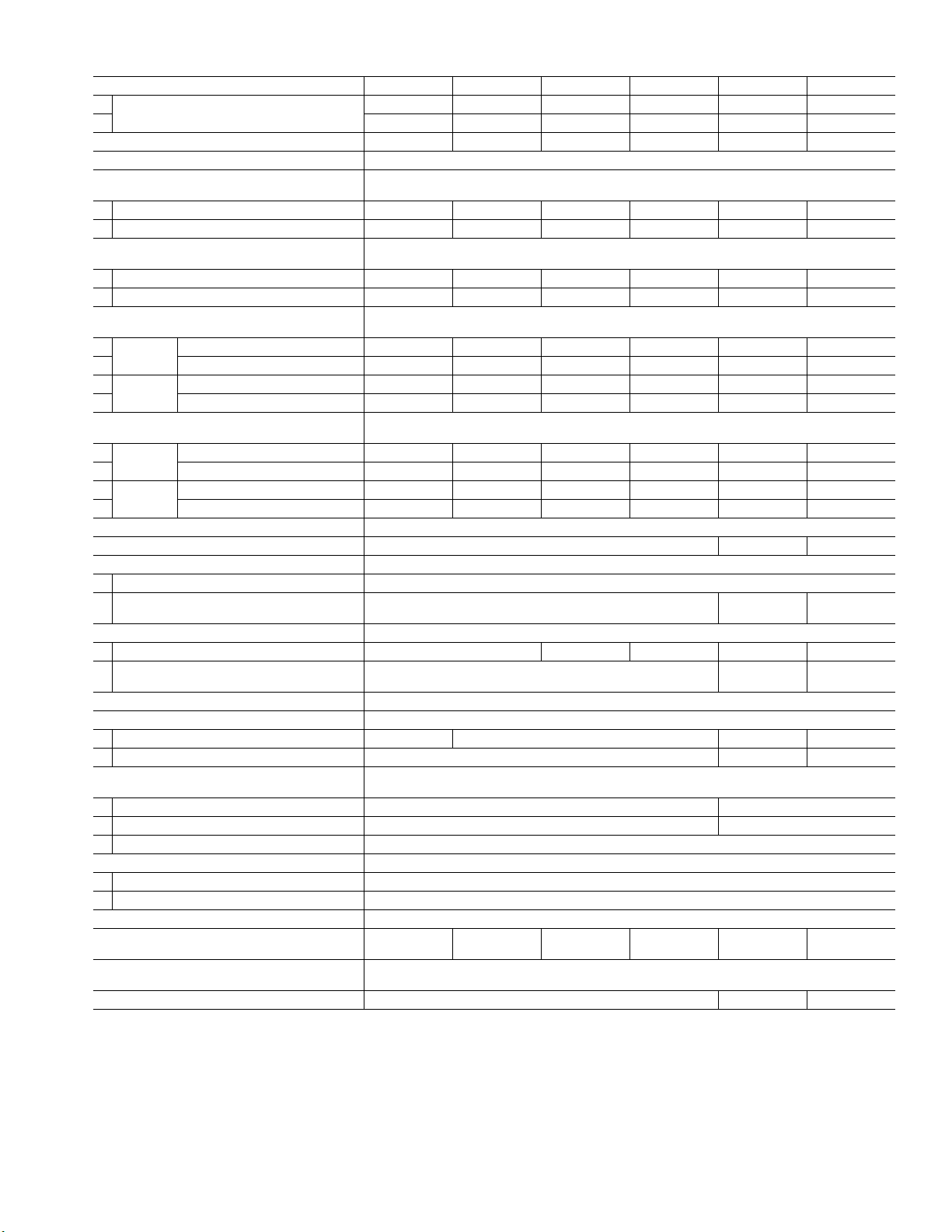
Table 3 — 38VMAH 208/230V Combination Units (2 Units)
COMBINATION UNIT MODEL NUMBER 168 192 216 240 264 288
Combination Units
NOMINAL CAPACITY (tons) 14 16 18 20 22 24
POWER SUPPLY (V-Ph-Hz)* 208/230-3-60
COOLING CAPACITY WITH NON-DUCTED
INDOOR UNITS†
Nominal (kBtu/h) 163.8 184.8 205.8 224.7 258.3 283.5
Rated (kBtu/h) 156.0 176.0 196.0 214.0 246.0 270.0
HEATING CAPACITY WITH NON-DUCTED
INDOOR UNITS†
Nominal (kBtu/h) 188.0 216.0 234.0 252.0 286.0 320.0
Rated (kBtu/h) 180.0 206.0 224.0 240.0 270.0 300.0
ELECTRICAL CHARACTERISTICS WITH
NON-DUCTED INDOOR UNITS
Cooling
Heating
Power Consumption (kW) 11.00 12.90 15.30 18.60 23.90 27.00
EER (Btu/W) 12.50 12.30 11.70 10.70 9.70 9.50
Power Consumption (kW) 12.40 14.70 16.70 18.40 22.80 26.00
COP (W/W) 3.80 3.75 3.62 3.54 3.27 3.20
ELECTRICAL CHARACTERISTICS WITH
DUCTED INDOOR UNITS
Cooling
Heating
Power Consumption (kW) 12.40 14.50 16.60 18.70 24.20 27.40
EER (Btu/W) 12.00 11.60 11.30 11.00 9.80 9.50
Power Consumption (kW) 13.90 16.10 17.80 19.50 23.80 26.40
COP (W/W) 3.64 3.60 3.54 3.47 3.20 3.20
UNIT DIMENSIONS (W X H X D) (in.) 52-
UNIT NET WEIGHT (lb) 659 (x2) 780 + 659 780 (x2)
COMPRESSOR
Type Hermetic Scroll Compressor (Inverter Driven)
Motor Output (kW) 23.25 (x2)
FAN UNIT
Air Volume 7650 (x2) 8250 + 7650 8250 (x2) 8830 + 8250 8830 (x2)
Motor Output (W) 270 (x4)
REFRIGERANT SHIPPING CHARGE (lb)** 37.5 (x2)
ELECTRICAL SPECIFICATIONS
MCA (A)†† 46 + 45 46 (x2) 70 + 46 70 (x2)
Recommended Fuse Size (A) 50 (x2) 80 + 50 80 (x2)
REFRIGERANT CONNECTING PORT
DIAMETER
Gas Side (in.) 1-
Liquid Side (in.)
Balance Pipe (in.)
OPERATION TEMPERATURE RANGE
Cooling (F db) 5~125
Heating (F wb) -5~64
MAX ESP (in. wg) 0.08
MAX NUMBER OF CONNECTED INDOOR
UNITS
MAX CAPACITY OF COMBINED INDOOR
UNITS***
SOUND PRESSURE LEVEL (DB(A)) ††† 65 66.5 67.5
LEGEND
COP — Coefficient of Performance
db — Dry Bulb
EER — Energy Efficiency Ratio
ESP — External Static Pressure
MCA — Maximum Circuit Amps
wb — Wet Bulb
* The source of voltage must not fluctuate more than ± 10%.
† Rated conditions:
Cooling: Indoor air temperature 80
Outdoor air temperature 95
Heating: 70
bulb / 43
° F dry bulb, Outdoor air temperature 47° F dry
° F wet bulb.
° F dry bulb / 67° F wet bulb,
° F dry bulb.
096 096 120 120 144 144
072 096 096 120 120 144
3
/4 (x2) x 64-3/8 x 31-1/
1
/
8
5
/
8
1
/
4
8
23.25 + 22.90
340 + 300 +
+ 13.80
270 (x2)
22.90 (x2) +
13.80 (x2)
340 (x2) +
300 (x2)
1-3/
8
3
/
4
29 33 36 39 46 50
50% to 135%
** The amount does not consider extra piping length. Refrigerant
must be added on site in accordance with the actual piping length.
†† Select wire size based on larger value of MCA.
*** In case the diversity exceeds 135%, the type of indoor unit is
limited and the maximum number of indoor unit is reduced.
††† These values, measured in anechoic chamber, at a point 1 m in
front of the unit at a height of 1.4 m. During actual operation,
these values are normally somewhat higher as a result of ambient
conditions.
5
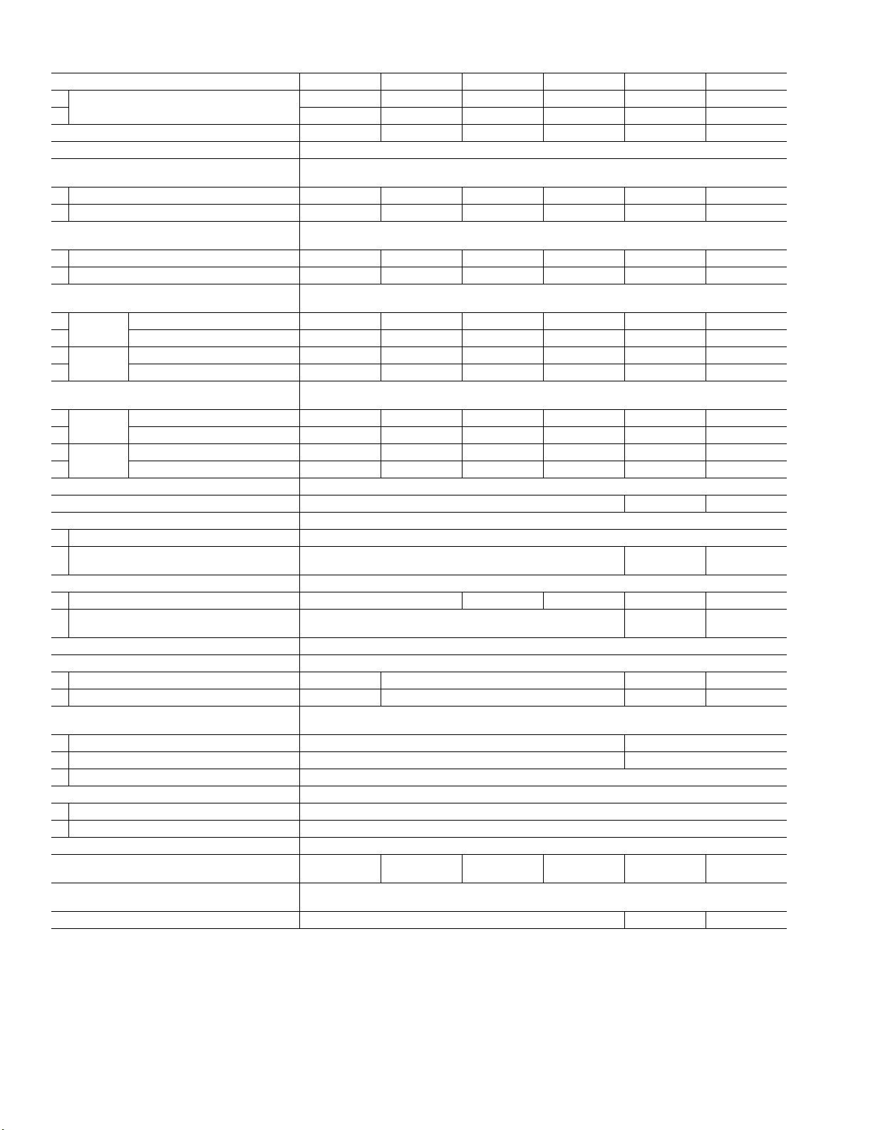
Table 4 — 38VMAH 460V Combination Units (2 Units)
COMBINATION UNIT MODEL NUMBER 168 192 216 240 264 288
Combination Units
NOMINAL CAPACITY (tons) 14 16 18 20 22 24
POWER SUPPLY (V-Ph-Hz)* 460-3-60
COOLING CAPACITY WITH NON-DUCTED
INDOOR UNITS†
Nominal (kBtu/h) 163.8 184.8 205.8 224.7 258.3 283.5
Rated (kBtu/h) 156.0 176.0 196.0 214.0 246.0 270.0
HEATING CAPACITY WITH NON-DUCTED
INDOOR UNITS†
Nominal (kBtu/h) 188.0 216.0 234.0 252.0 286.0 320.0
Rated (kBtu/h) 180.0 206.0 224.0 240.0 270.0 300.0
ELECTRICAL CHARACTERISTICS WITH
NON-DUCTED INDOOR UNITS
Cooling
Heating
ELECTRICAL CHARACTERISTICS WITH
DUCTED INDOOR UNITS
Cooling
Heating
Power Consumption (kW) 11.00 12.90 15.30 18.60 23.90 27.00
EER (Btu/W) 12.50 12.30 11.70 10.70 9.70 9.50
Power Consumption (kW) 12.40 14.70 16.70 18.40 22.80 26.00
COP (W/W) 3.80 3.75 3.62 3.54 3.27 3.20
Power Consumption (kW) 12.40 14.50 16.60 18.70 24.20 27.40
EER (Btu/W) 12.00 11.60 11.30 11.00 9.80 9.50
Power Consumption (kW) 13.90 16.10 17.80 19.50 23.80 26.40
COP (W/W) 3.64 3.60 3.54 3.47 3.20 3.20
UNIT DIMENSIONS (W X H X D) (in.) 52-
UNIT NET WEIGHT (lb) 659 (x2) 772 + 659 772 (x2)
COMPRESSOR
Type Hermetic Scroll Compressor (Inverter Driven)
Motor Output (kW) 23.25 (x2)
FAN UNIT
Air Volume 7650 (x2) 8250 + 7650 8250 (x2) 8250 + 8830 8830 (x2)
Motor Output (W) 270 (x4)
REFRIGERANT SHIPPING CHARGE (lb)** 37.5 (x2)
ELECTRICAL SPECIFICATIONS
MCA (A)†† 25 + 22 25 (x2) 33 + 25 33 (x2)
Recommended Fuse Size (A) 30 + 25 30 (x2) 35 + 30 35 (x2)
REFRIGERANT CONNECTING PORT
DIAMETER
Gas Side (in.) 1-
Liquid Side (in.)
Balance Pipe (in.)
OPERATION TEMPERATURE RANGE
Cooling (F db) 5~125
Heating (F wb) -5~64
MAX ESP (in. wg) 0.08
MAX NUMBER OF CONNECTED INDOOR
UNITS
MAX CAPACITY OF COMBINED INDOOR
UNITS***
SOUND PRESSURE LEVEL (DB(A)) ††† 65.0 66.5 67.5
LEGEND
COP — Coefficient of Performance
db — Dry Bulb
EER — Energy Efficiency Ratio
ESP — External Static Pressure
MCA — Maximum Circuit Amps
wb — Wet Bulb
* The source of voltage must not fluctuate more than ± 10%.
† Rated conditions:
Cooling: Indoor air temperature 80
Outdoor air temperature 95
Heating: 70
bulb / 43
° F dry bulb, Outdoor air temperature 47° F dry
° F wet bulb.
° F dry bulb / 67° F wet bulb,
° F dry bulb.
096 096 120 120 144 144
072 096 096 120 120 144
3
/4 (x2) x 64-3/8 x 31-1/
1
/
8
5
/
8
1
/
4
8
23.25 + 22.90
+ 13.80
270 (x2) +
300 + 340
22.90 (x2) +
13.80 (x2)
300 (x2) +
340 (x2)
1-3/
8
3
/
4
29 33 36 39 46 50
50% to 135%
** The amount does not consider extra piping length. Refrigerant
must be added on site in accordance with the actual piping length.
†† Select wire size based on larger value of MCA.
*** In case the diversity exceeds 135%, the type of indoor unit is
limited and the maximum number of indoor unit is reduced.
††† These values, measured in anechoic chamber, at a point 1 m in
front of the unit at a height of 1.4 m. During actual operation,
these values are normally somewhat higher as a result of ambient
conditions.
6
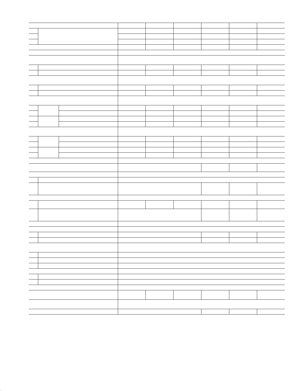
Table 5 — 38VMAH 208/230V Combination Units (3 Units)
COMBINATION UNIT MODEL NUMBER 312 336 360 384 408 432
120 120 120 144 144 144
Combination Units
NOMINAL TONS (Ton)
POWER SUPPLY (V-Ph-Hz)*
COOLING CAPACITY WITH NON-DUCTED
INDOOR UNITS†
Nominal (kBtu/h)
Rated (kBtu/h)
HEATING CAPACITY WITH NON-DUCTED
INDOOR UNITS†
Nominal (kBtu/h)
Rated (kBtu/h)
ELECTRICAL CHARACTERISTICS WITH NONDUCTED INDOOR UNITS
Cooling
Heating
ELECTRICAL CHARACTERISTICS WITH
DUCTED INDOOR UNITS
Cooling
Heating
Power Consution (kW)
EER (Btu/W)
Power Consumption (kW)
COP (W/W)
Power Consumption (kW)
EER (Btu/W)
Power Consumption (kW)
COP (W/W)
UNIT DIMENSIONS (W x H x D)
UNIT NET WEIGHT (lb)
COMPRESSOR
Type
Motor Output (kW)
FAN UNIT
Air Volume (cfm)
Motor Output (W)
REFRIGERANT SHIPPING CHARGE (lb)**
ELECTRICAL SPECIFICATIONS
MCA (A)††
Recommended Fuse Size (A)
REFRIGERANT CONNECTING PORT
DIAMETER
Gas Side (in.)
Liquid Side (in.)
Balance Pipe (in.)
OPERATION TEMPERATURE RANGE
Cooling (F db) 5~125
Heating (F wb) -5~64
MAX ESP (in. wg)
MAX NUMBER OF CONNECTED INDOOR
UNITS
MAXIMUM CAPACITY OF COMBINED INDOOR
UNITS***
SOUND PRESSURE LEVEL (db(A))†††
LEGEND
COP — Coefficient of Performance
db — Dry Bulb
EER — Energy Efficiency Ratio
ESP — External Static Pressure
MCA — Maximum Circuit Amps
wb — Wet Bulb
* The source of voltage must not fluctuate more than ± 10%.
† Rated conditions:
Cooling: Indoor air temperature 80
Outdoor air temperature 95
Heating: 70
bulb / 43
° F dry bulb, Outdoor air temperature 47° F dry
° F wet bulb.
° F dry bulb / 67° F wet bulb,
° F dry bulb.
096 120 120 120 144 144
096 096 120 120 120 144
26 28 30 32 34 36
208/230-3-60
298.2 319.2 342.3 373.8 399.0 420.0
284.0 304.0 326.0 356.0 380.0 400.0
342.0 360.0 378.0 412.0 446.0 480.0
320.0 338.0 354.0 384.0 410.0 440.0
24.10 27.00 30.55 34.90 38.60 40.70
11.10 10.70 10.20 9.80 9.50 9.50
25.90 28.50 31.00 33.70 36.10 38.90
3.43 3.31 3.20 3.20 3.20 3.20
25.70 27.40 29.90 35.90 38.30 40.30
10.60 10.60 10.40 9.50 9.50 9.50
27.30 29.20 31.00 33.60 35.90 38.50
3.30 3.25 3.20 3.20 3.20 3.20
3
/4 (x3) x 64-3/8 x 31-1/
52-
659 (x3)
780 +
659 (x2)
8
780 (x2) +
659
780 (x3)
Hermetic Scroll Compressor (Inverter Driven)
8250 +
7650 (x2)
23.25 (x3)
8250 (x2) +
7650
270 (x6)
8250 (x3)
23.25 (x2) +
22.90 + 13.80
8830 + 8250
(x2)
340 + 300 +
270 (x4)
23.25 + 22.9
(x2) + 13.8
(x2)
8830 (x2) +
8250
340 (x2) +
300 (x2) +
270 (x2)
22.9 (x3) +
13.8 (x3)
8830 (x3)
340 (x3) +
300 (x3)
37.5 (x3)
46 (x3) 70 + 46 (x2) 70 (x2) + 46 70 (x3)
50 (x3) 80 + 50 (x2) 80 (x2) + 50 80 (x3)
3
1-
/
8
3
/
4
1
/
4
0.08
53 56 59 63 64 64
50% to 135%
66.5 67.0 68.5 69.0
** The amount does not consider extra piping length. Refrigerant
must be added on site in accordance with the actual piping length.
†† Select wire size based on larger value of MCA.
*** In case the diversity exceeds 135%, the type of indoor unit is
limited and the maximum number of indoor unit is reduced.
††† These values, measured in anechoic chamber, at a point 1 m in
front of the unit at a height of 1.4 m. During actual operation,
these values are normally somewhat higher as a result of ambient
conditions.
7
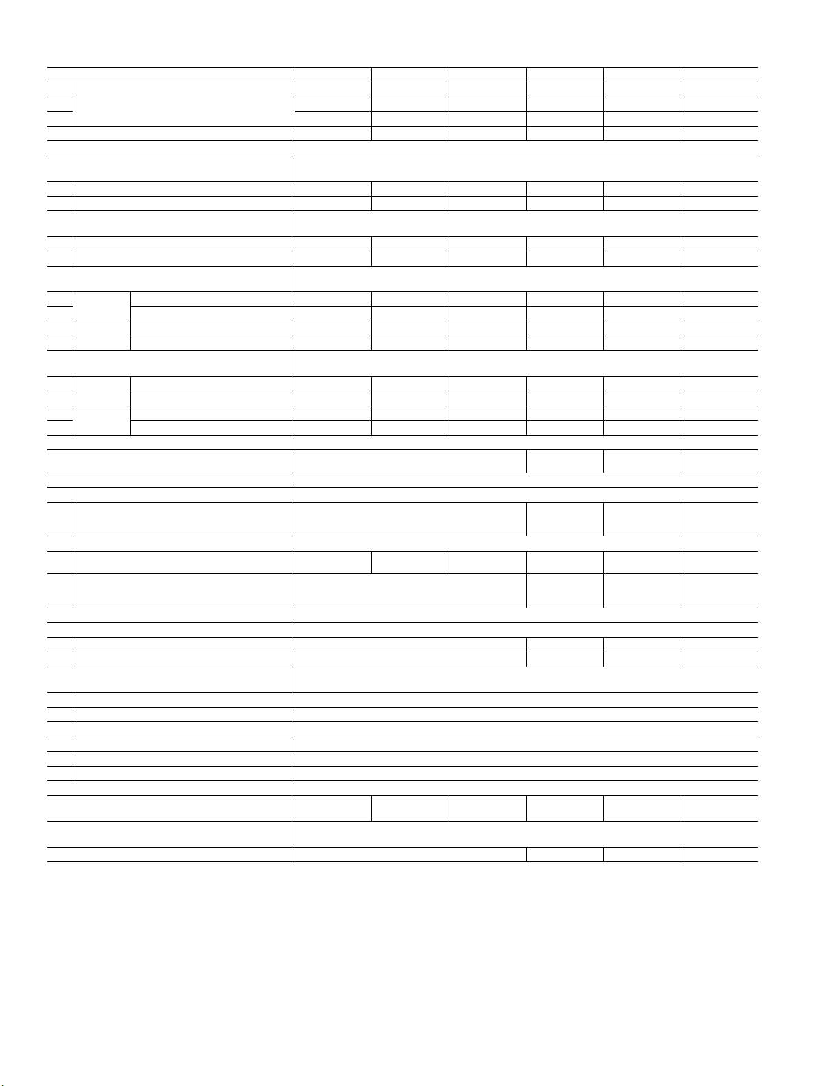
Table 6 — 38VMAH 460V Combination Units (3 Units)
COMBINATION UNIT MODEL NUMBER 312 336 360 384 408 432
Combination Units
NOMINAL TONS (Ton)
POWER SUPPLY (V-Ph-Hz) *
COOLING CAPACITY WITH NON-DUCTED
INDOOR UNITS †
Nominal (kBtu/h)
Rated (kBtu/h)
HEATING CAPACITY WITH NON-DUCTED
INDOOR UNITS †
Nominal (kBtu/h)
Rated (kBtu/h)
ELECTRICAL CHARACTERISTICS WITH
NON-DUCTED INDOOR UNITS
Cooling
Heating
Power Consumption (kW)
EER (Btu/W)
Power Consumption (kW)
COP (W/W)
ELECTRICAL CHARACTERISTICS WITH
DUCTED INDOOR UNITS
Cooling
Heating
Power Consumption (kW)
EER (Btu/W)
Power Consumption (kW)
COP (W/W)
UNIT DIMENSIONS (W x H x D)
UNIT NET WEIGHT (lb)
COMPRESSOR
Type
Motor Output (kW)
FAN UNIT
Air Volume (cfm)
Motor Output (W)
REFRIGERANT SHIPPING CHARGE (lb)**
ELECTRICAL SPECIFICATIONS
MCA (A)††
Recommended Fuse Size (A)
REFRIGERANT CONNECTING PORT
DIAMETER
Gas Side (in.)
Liquid Side (in.)
Balance Pipe (in.)
OPERATION TEMPERATURE RANGE
Cooling (F db) 5~125
Heating (F wb) -5~64
MAX ESP (in. wg)
MAX NUMBER OF CONNECTED INDOOR
UNITS
MAXIMUM CAPACITY OF COMBINED
INDOOR UNITS***
SOUND PRESSURE LEVEL (db(A))†††
LEGEND
COP — Coefficient of Performance
db — Dry Bulb
EER — Energy Efficiency Ratio
ESP — External Static Pressure
MCA — Maximum Circuit Amps
wb — Wet Bulb
* The source of voltage must not fluctuate more than ± 10%.
† Rated conditions:
Cooling: Indoor air temperature 80
Outdoor air temperature 95
Heating: 70
bulb / 43
° F dry bulb, Outdoor air temperature 47° F dry
° F wet bulb.
° F dry bulb / 67° F wet bulb,
° F dry bulb.
120 120 120 144 144 144
096 120 120 120 144 144
096 096 120 120 120 144
26 28 30 32 34 36
460-3-60
298.2 319.2 342.3 373.8 399.0 420.0
284.0 304.0 326.0 356.0 380.0 400.0
342.0 360.0 378.0 412.0 446.0 480.0
320.0 338.0 354.0 384.0 410.0 440.0
24.10 27.00 30.50 34.90 38.60 40.70
11.10 10.70 10.20 9.80 9.50 9.50
25.90 28.50 31.00 33.70 36.10 38.90
3.43 3.31 3.20 3.20 3.20 3.20
25.70 27.40 29.90 35.90 38.30 40.30
10.60 10.60 10.40 9.50 9.50 9.50
27.30 29.20 31.00 33.60 35.90 38.50
3.30 3.25 3.20 3.20 3.20 3.20
3
/4 (x3) x 64-3/8 x 31-1/
52-
659 (x3)
772 +
659 (x2)
8
772 (x2) +
659
Hermetic Scroll Compressor (Inverter Driven)
23.25 +
22.90 (x2) +
13.8 (x2)
8830 (x2) +
8250
340 (x2) +
300 (x2) +
270 (x2)
8250 + 7650
(x2)
23.25 (x3)
8250 (x2) +
7650
270 (x6)
8250 (x3)
23.25 (x2) +
22.90 + 13.8
8830 + 8250
(x2)
340 + 300 +
270 (x4)
37.5 (x3)
25 (x3) 33 + 25 (x2) 33 (x2) + 25 33 (x3)
30 (x3) 35 + 30 (x2) 35 (x2) + 30 35 (x3)
3
1-
/
8
3
/
4
1
/
4
0.08
53 56 59 63 64 64
50% to 135%
66.5 67.0 68.5 69.0
** The amount does not consider extra piping length. Refrigerant
must be added on site in accordance with the actual piping length.
†† Select wire size based on larger value of MCA.
*** In case the diversity exceeds 135%, the type of indoor unit is
limited and the maximum number of indoor unit is reduced.
††† These values, measured in anechoic chamber, at a point 1 m in
front of the unit at a height of 1.4 m. During actual operation,
these values are normally somewhat higher as a result of ambient
conditions.
772 (x3)
22.9 (x3) +
13.8 (x3)
8830 (x3)
340 (x3) +
300 (x3)
8
 Loading...