

Page 1
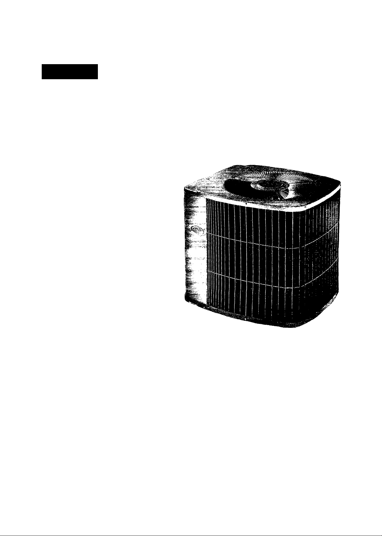
Carrier )
38 YD
TWO-SPEED
A GUIDE TO OPERATING
AND MAINTAINING
YOUR RESIDENTIAL
HEAT PUMP UNIT,
SYNERGY 2000
NOTE TO INSTALLER:
This manual should be left with equipment user.
Page 2
WELCOME TO EFFICIENT YEAR-ROUND COMFORT
Congratulations on your excellent choice and sound invest
ment in year-round home comfort!
Your new heat pump represents both the latest in engineering
development and the culmination of many years of experience
from one of the most reputable manufacturers of comfort
systems.
Your new unit is among the most energy-efficient and reliable
heat pump products available today. To assure its dependabil
ity, spend just a few minutes with this booklet now. Learn
about the operation of your heat pump, and the small amount of
maintenance it takes to keep it operating at its peak efficiency.
With minimal care, your new heat pump will provide you and
your family with year-round home comfort—both now and for
years to come.
A WARNING
Improper installation, adjustment, alteration, service,
maintenance or use can cause explosion, fire, electrical
shock, or other conditions which may cause personal injury
or property damage. Consult a qualified installer, service
agency or your distributor or branch for information or as
sistance. The qualified installer or agency must use fac
tory-authorized kits or accessories when modifying this
product.
A WARNING
To prevent personal injury, death, or property damage, be
fore operating your new heat pump, read and follow all in
structions and warnings, including labels shipped with or
attached to unit.
YOUR COMFORT SYSTEM
Identifying Your System
Thke the time to familiarize yourself with the type of system
you have. This knowledge will be of use in understanding the
basic operation of your new heat pump.
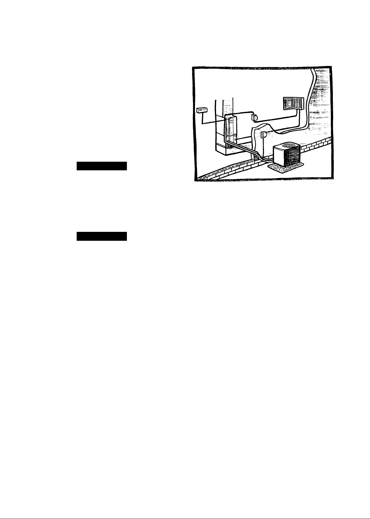
The split-system type has an indoor and an outdoor unit, each
of which contains a coil. These units are interconnected by re
frigerant tubes, as shown in Fig. 1.
Each unit has a rating plate affixed to it. A rating plate provides
necessary information for specific identification of a unit. You
should familiarize yourself with the product, model, and serial
numbers listed on each rating plate.
IMPORTANT FACTS
To better protect your investment and to eliminate unnecessary
service calls, familiarize yourself with the following facts:
• Your heat pump system should never be operated without a
clean air filter properly installed. Plan to inspect the filter peri
odically. A clogged air filter will increase operating costs and
shorten the life of the unit.
• Supply-air and return-air registers should not be blocked.
Drapes, furniture, and toys are some of the items commonly
found obstructing grilles. Restricted airflow lessens the unit’s
efficiency and life span.
• The outdoor unit must have unrestricted airflow. Do not
cover the unit, lean anything against it, or stand upon it. Do not
allow grass clippings, leaves, or other debris to accumulate
around or on top of the unit. Maintain a 12-in. minimum clear
ance between the outdoor unit and tall grass, vines, shrubs, etc.
Fig. 1—Typical Split-System Instaliation
• Your multipurpose indoor thermostat is the control center
for your heat pump system. You should familiarize yourself
with its proper operation. Attempting to control the system by
other means—for instance, switching the electrical supply
power ON and OFF-—may cause damage to the unit.
• Thermostat “jiggling” causes rapid-cycling, which is poten
tially damaging to the compressor. Do not move the tempera
ture selector on the thermostat for any reason for at least 5
minutes after the compressor has shut off.
• During the heating season, never increase the indoor thermo
stat setting more than 1 or 2-degree increments. If larger adjust
ments are made, the supplementary heating source will be
turned on automatically. Needless use of the supplementary
heat reduces potential energy savings.
• You may find that you can maintain greater personal comfort
by running the fan continuously. “Air pockets” can form due to
the structure of the house, placement of registers, etc. These air
pockets may be too cool or warm for your liking. Continuous fan
operation minimizes any temperature differences. Also, sys
tems equipped with electronic air cleaners and/or humidifiers
offer the added benefits of having the air continuously cleaned
year-round, and humidified during the winter season.
• Your heat pump will remove humidity from your home dur
ing the cooling season. After a few minutes of operation, you
should be able to see water trickle from the condensate drain of
the cooling coil. Check this occasionally to be sure the drain
system is not clogged. Of course, don’t expect to see much drain
age if you live in a very dry environment.
• During the heating cycle, air from your registers may seem
cooler than you might first expect. This is because the air is be
ing delivered at a higher velocity and a more constant flow than
air supplied by a conventional furnace. Also, your heat pump
supplies air at 85 to 90°F instead of in sudden bursts of hot air
as with a conventional furnace. The air may feel cool because it
is slightly less than your body temperature. However, it is suffi
ciently warm to keep you comfortable.
• Ice or frost will tend to form on the outdoor coil during the
winter heating operation. Your heat pump is designed to auto
matically melt the ice. When in this defrost cycle, it is normal
Page 3
A91281
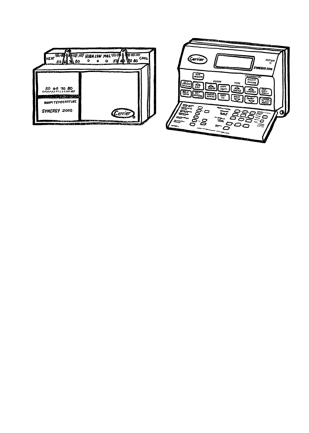
Fig. 2—Auto Changeover
Thermostat
for steam or fog to rise from the outdoor unit. Do not be
alarmed!
• Do not operate your unit in cooling mode when outdoor tem
peratures are below 55 °P.
• Do not operate your unit in heating mode when outdoor tem
peratures are above 66°F.
OPERATING YOUR HEAT PUMP
The operation of your heat pump system is controlled by the
indoor thermostat. You simply adjust the thermostat and it
maintains the indoor temperature at the level you select. Most
thermostats for heat pump systems have 3 controls: the tem
perature control selector, FAN switch, and SYSTEM switch.
The temperature control selector is a dial or lever that allows
you to establish the degree of temperature that you wish to
maintain for your personal comfort. Some thermostats possess
2 temperature control selectors: one for setting the temperature
desired during the cooling cycle, and one to set the heating oper
ation temperature. TVpical settings are 78°F for cooling and
68 °F for heating.
The FAN switch offers 2 options for controlling the blower:
AUTO and ON. When set to AUTO, the blower will run during
the time the heat pump is operating. When the FAN switch is
set at the ON position, the blower will run continuously.
Typically, the SYSTEM switch on your thermostat offers the
following selections: EM HEAT, HEAT, OFF, AUTO, and
COOL. The heat pump will not operate when the SYSTEM
switch is set at the OFF position. With the SYSTEM switch set
at COOL, your heat pump will operate in its cooling mode when
the indoor temperature rises above the level that you wish to
maintain. With the SYSTEM switch set at the HEAT position,
your heat pump will provide warmth whenever the indoor tem
perature falls below the level that you have selected.
The AUTO selection found on some thermostats provides for
automatic changeover between cooling and heating cycles.
With the SYSTEM switch set in the AUTO position, the cool
ing mode is activated when the indoor temperature rises above
the thermostat cooling temperature setting, or the heating
mode will be activated when the indoor temperature drops be
low the thermostat setting for the heating cycle.
Fig. 3—Night Setback
Thermostat
If equipped with and you wish to program your accessory elec
tronic indoor thermostat, please refer to thermostat installa
tion instructions.
Depending on your typical winter heating needs, your home
comfort system may include a supplementary heating source.
When the system switch is set to HEAT, your heat pump will
operate normally and supplementary heat will be added as
needed. With the system switch set to EM HEAT, the heat
pump will turn off and the supplementary heat source will sup
ply all your home heating needs.
NOTE: Your two-speed heat pump system has several special
features built in to protect the unit.
• 5-MINUTE TIME DELAY—unit will delay operation upon
initial start-up or short cycling of the indoor thermostat.
• 1-MINUTE TIME DELAY—when changing speeds from
low to high, or high to low, there is a 1-minute time delay. Dur
ing the speed change delay the outdoor fan will continue to run.
• 2-MINUTE LOW-SPEED MINIMUM—if the unit has not
operated within the past 30 minutes, upon the next cooling de
mand, it will operate for a minimum of 2 minutes on low speed.
COOLING CYCLE
When operating in the cooling cycle, your heat pump will run
until the indoor temperature is lowered to the level you have se
lected. On extremely hot days, your conditioner will run for
longer periods at a time and have shorter “off’ periods than on
moderate days.
The following are typical conditions that add extra heat and/or
humidity to your home. Your cooling unit will work longer to
keep your home comfortable under these conditions:
• Entrance doors are frequently opened and closed
• Laundry appliances are being operated
• A shower is running
• More than the usual number of people are present in the
home
• More than the normal number of electric lights are in use
• Drapes are open on the sunny side of the home
HEATING CYCLE
With the SYSTEM switch of your indoor thermostat set to the
HEAT position, the heating section of your home comfort sys
Page 4
tem will operate until room temperature is raised to the level
you have selected. Of course, the heating unit will have to oper
ate for longer periods to maintain a comfortable environment
on cooler days and nights than on moderate ones.
If supplementary heating source is a furnace, refer to your fur
nace user’s manual for specific information on heating
operation.
DEFROST CYCLE
When your heat pump is providing heat to your home and the
outdoor temperature drops below 45 °F, moisture may begin to
freeze on the surface of the outdoor coil. If allowed to build up,
this ice would impede airflow across the coil and reduce the
amount of heat absorbed from the outside air. So, to maintain
energy-efficient operation, your heat pump has an automatic
defrost cycle.
minutes for any reason (i.e., power outage). Leave the switch in
the EMERGENCY HEAT position for an amount of time equal
to that during which the power was off. It isn’t necessary to ex
ceed 12 hours. If you cannot determine how long the power has
been off, leave the switch in the EMERGENCY HEAT position
for 8 hours.
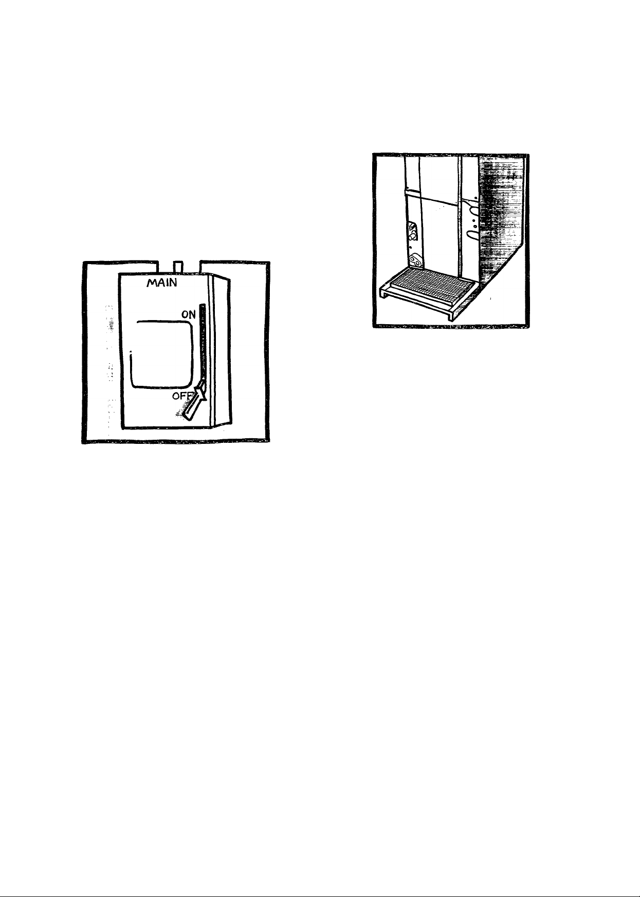
Fig. 5—Removing Filter from
Fan Coil Unit
Fig. 4—Main Electrical Disconnect
The defrost cycle starts at a preset time interval of 90 minutes,
although it may be reset to either 30 or 50 minutes. Defrost will
start at the preset time only if the ice is sufficient to interfere
with normal heating operation.
After the ice is melted from the outdoor coil, or after a maxi
mum of 10 minutes in the defrost mode, the unit will automati
cally switch back to normal heating operation.
Do not be alarmed if steam or fog appears at the outdoor unit
during the defrost cycle. Water vapor from the melting ice may
evaporate into a mist in the cold outside air.
During certain weather conditions such as heavy snow and
freezing rain it is not uncommon for ice to build up on the out
door unit grille. This is normal for these weather conditions. Do
not attempt to remove the ice from the outdoor unit grille. This
condition will not affect the proper function of the unit and will
clear within a few days.
SUPPLEMENTARY HEAT
Operation of the SUPPLEMENTARY HEAT source may be re
quired if heating demands exceed the capacity of the heat
pump, or if the heat pump malfunctions.
The red AUX. light on your thermostat will glow if the SUP
PLEMENTARY HEAT is in use. This indicates that the sup
plemental heating appliance is selected for operation.
Also, if your particular model of heat pump includes an “effi
ciency alarm” circuit, the MAL light will glow if the compressor
malfunctions. Call your dealer for immediate service if you sus
pect trouble.
During the heating season, switch to EMERGENCY HEAT if
the electricity to your outdoor unit has been off for more than 30
PERFORMING ROUTINE MAINTENANCE
With the proper maintenance and care, your heat pump unit
will operate economically and dependably. Maintenance can be
accomplished easily by referring to the following directions.
However, before performing maintenance, consider these im
portant safety precautions:
• DISCONNECT ALL ELECTRICAL POWER TO THE
AIR CONDITIONER BEFORE REMOVING ACCESS
PANELS TO PERFORM MAINTENANCE. Disconnect
power to both the indoor and outdoor units. NOTE: THERE
MAY BE MORE THAN ONE ELECTRICAL DISCONNECT
SWITCH.
• ALTHOUGH SPECIAL CARE HAS BEEN TAKEN TO
MINIMIZE SHARP EDGES IN THE CONSTRUCTION OF
YOUR UNIT, BE EXTREMELY CAREFUL WHEN HAN
DLING PARTS OR REACHING INTO THE UNIT.
CHECK THE AIR FILTER
A dirty air filter will cause excessive strain on the compressor
and blower motor, causing the components to overheat and au
tomatically shut down. In the extreme, the components will fail
and need to be replaced. To avoid inefficient or failed operation
of your unit, CHECK THE FILTER(S) EVERY 3 TO 4
WEEKS. Replace filter(s) when necessary, or clean the filter(s)
if you have the reusable t5rpe.
Disposable filters should be replaced by similar, new filters of
the same dimensions.
Reusable, permanent filters should be washed in a solution of
cold water and mild detergent, then rinsed and thoroughly
dried. THE FILTER MUST BE COMPLETELY DRY BE
FORE BEING REINSTALLED. To avoid prolonged shutdown
of your unit while a filter is drying, you should have an extra
filter on hand, allowing you to rotate between the two with min
imal downtime for your comfort system. Extra filters may be
purchased from your dealer.
There are no filters in the outdoor unit of a split-system. If your
indoor unit is a gas or oil furnace, refer to your furnace owner’s
manual for filter location and procedures for replacement or
cleaning.
Page 5
If your system includes an indoor fan coil unit, the filter is lo
cated in the unit where it connects with the return-air duct or
plenum. (See Fig. 5.) Remove the filter cover plate by sliding
latches toward center of plate. Lift filter to clear lower flange.
Filter is spring loaded and will “pop out.” Reinstall filter, being
certain to secure filter behind lower flange. When reinstalling
cover plate, secure plate behind upper flange then slide tabs
outward.
INDOOR COIL
If the indoor coil has only been operated with a clean filter in
place, it should require minimal cleaning. You may use a vac
uum cleaner and soft brush attachment to remove any accumu
lation of dust from the top and underside of the finned coil
surface. However, perform this maintenance only when the coil
is completely dry.
If you cannot get the coil clean by this method call your dealer
for service. It may be necessary to clean the coil with a detergent
solution and rinse it with water. This could require the removal
of the coil. You should not attempt this yourself.
OUTDOOR COIL
If grass clippings, leaves, shrubbery, and debris are kept away
from the outdoor unit, minimal care should be sufficient to
keep the system functioning properly. For proper drainage, de
bris must be removed periodically from the base pan. However,
if the outdoor coil becomes dirty, use a brush or vacuum cleaner
and soft brush attachment to clean the exterior surface. If dirt
is deep in the coil, contact your dealer for service. The outdoor
fan motor may have to be disconnected and the top panel re
moved to gain access to the coil for thorough cleaning. Do not
attempt this yourself.
OUTDOOR COIL—SEA COAST
If your unit is located near the ocean, special maintenance is
required. Ocean mist/breeze carries salt, which is corrosive to
most metals. Although your new unit is made out of galvanized
metal and is protected by top grade paint, you should take the
precaution of additional maintenance, consisting of periodic
washing of the unit. By washing all exposed surfaces and coil
you will be adding additional life to your unit. Please consult
your installing contractor for proper intervals/procedures for
your geographic area or service contact.
UNIT SUPPORT
Your split-system outdoor unit should be maintained at a level
position. If its support should shift or settle so that the unit is
no longer level, you should correct the condition. Relevel it
promptly to assure condensate drainage out of the unit. If you
notice that water or ice collects beneath the unit, arrange for it
to be drained away from the unit.
BEFORE YOU REQUEST A
“SERVICE CALL”
BEFORE YOU CALL FOR SERVICE, CHECK FOR THESE
EASILY SOLVED PROBLEMS:
• Check the indoor and outdoor disconnect switches. Verify
that circuit breakers are ON or that fuses have not blown.
• Check for sufficient airflow. Check the air filter(s) for any ac
cumulations of dirt. Check for blocked return-air or supply-air
grilles. Be sure grilles are open and unobstructed.
• Check the settings on your indoor thermostat. If you desire
cooling, see that the temperature control selector is set below
room temperature and the SYSTEM switch is on the COOL or
AUTO position. If you require warmth, be sure the temperature
control selector is set above room temperature and the SYS
TEM switch is at HEAT or AUTO. The FAN switch should be
set at ON for continuous blower operation or AUTO if you wish
blower to function only while the unit is operating.
• Check note concerning special features and time delays in
section titled “Operating Your Air Conditioner.”
• If MAL LED light on thermostat is flashing, record pattern
of consecutive flashes and pauses (i.e. 1 flash with pause, 2
flashes with pause . . . ) and report to service person when con
tacted. This will assist service personnel in diagnosing system
problems.
If your comfort system still fails to operate, contact your servic
ing dealer for troubleshooting and repairs. Specify your appar
ent problem, and state the model and serial numbers of your
equipment. (You should have them recorded on page 6 of this
booklet.) With this information, your dealer may be able to of
fer helpful suggestions over the phone or save valuable time
through knowledgeable preparation for the service call.
REGULAR DEALER MAINTENANCE
In addition to the routine
maintenance that you per
form, your home comfort sys
tem should be inspected
regularly by a properly
trained service technician.
The inspection (preferably
each year, but at least every
other year) should include the
following;
• Routine inspection of air filter(s). Replacement or cleaning
as required.
• Inspection and cleaning of the blower wheel, housing, and
motor as required.
• Inspection and, if required, cleaning of indoor and outdoor
coils.
• Inspection of the indoor coil drain pan, plus the primary and
secondary drain lines. If supplied, the auxiliary drain pan and
line should be inspected at this time. Service should include
cleaning if required.
• A check of all electrical wiring and connections.
• A check for secure physical connections of individual compo
nents within units.
• Operational check of the heat pump system to determine ac
tual working condition. Necessary repair and/or adjustment
should be performed at this time.
Your servicing dealer may offer an economical service contract
that covers seasonal inspections. Ask for iurther details.
Page 6

FOR THE RECORD
Record the model, product, and serial numbers of your new
equipment in the spaces provided below. This information,
along with the other ready-reference facts requested below, will
be necessary should you ever require information or service.
Installation Data
Date Installed
------------------------------------------------------------------
Dealer Name.
Address
City
_____
-------------
Modular Indoor Unit, if Applicable:
Blower—Product No---------------------
Model No_______________
Serial No
_______________
State.
Tfelephone.
Outdoor Unit:
Product No
Model No
Serial No
___
____
_____
Indoor Unit or Coil:
Product No
________
Model No__________
Serial No
__________
.Zip.
Split-System
Coil—Product No..
Model No
Serial No
___
___
Heater—Product No..
Model No
Serial No
___
___
Page 7

IMPORTANT: Complete, detach and mail immediately for. . .
PRODUCT REGISTRATION
THE FEDERAL CONSUMER PRODUCT SAFETY ACT REQUIRES THAT YOU BE NOTIFIED OF ANY RECALLS INVOLVING
THIS PRODUCT. YOUR NAME AND ADDRESS AND THE MODEL AND SERIAL NUMBERS OF YOUR PRODUCT WILL ASSIST
US IN NOTIFYING YOU SHOULD THE NEED ARISE.
1. 1. □ Mr. 2. □ Mrs. 3. □ Ms. 4. □ Miss
Name (First/lnitlal/Last)
I I I I I I I I I I I I I I I
Street
i I I I i I I I I I I I I I I I I I i I I I I I I ■ l-_ I
City State Zip
I I I I I I I I I I I I I I I I I I I I I I
I I I I I I I I I I I I I I I I I I I I I I
2. DATE INSTALLED . _Z_
3. What Carrier product did you purchase?
1. □ Central air conditioner
2. □ Gas furnace
3. □ Oil furnace
4. □ Electric furnace
5. □ Heat pump
4. When did you acquire your Carrier product?
1. □ Upon purchase of new dwelling
2. □ To replace an older Carrier system
3. □ To replace an older non-Carrier system
4. □ Within a year of buying new dwelling with no
central air system
5. □ Over 4 years after buying dwelling with no
central air system
5. if this was a replacement product, how old was the
original?
1. □ 1-5 years 4. □ 12-14 years
2. □ 6-8 years 5. □ 15-17 years
3. □ 9-11 years 6. □ 18 & over years
6. Your product is installed in?
1. □ Single family/Townhouse
2. □ Multi-family: 2-4
3. D Mobile home
4. D Apartment: 1-3 floors
5. □ Apartment: 4 + floors
6. □ Office/Bank
7. □ Store
8. □ Hospital/School
9. □ Manufacturing building
10. □ Other
7. What 2 factors most influenced your purchase?
1. □ Our reputation
2. □ Friend's recommendation
3. □ Contractor/Dealer’s
recommendation
4. □ Price
5. □ Energy efficiency
Your warranty coverage is not dependent upon the return of this card.
I I I I I I I I
MODEL NO. (Copy from rating plate on unit.) SERIAL NO.
8. Which of the following have you done in the past 6
Mo. Day Yr.
6. □ Ready availability
7. □ Radio ads
8. □ TV. ads
9. □ Newspaper ads
10. □ Magazine ads
11. □ Dealer display
months? (check all that apply)
1. □ Redeemed a product coupon
2. □ Ordered an item from mail order catalog
3. □ Sent in product inquiry card from magazine
4. □ Bought an item from offer received in mail
5. □ Entered sweepstakes/contest
9. In which age group are you?
1. □ 18-24
2. □ 25-34
3. □ 35-44
4. □ 45-54
5. □ 55-64
6. □ 65 & over
10. Marital status:
1. □ Married
11. Which group best describes your family income?
1. □ Under $10,000 6. □ $30.000-$34,999
2. □ $10,000-$14,999 7. O $35,000-$39,999
3. □ $15,0Q0-$19,999 8. □ $40,000-$44,999
4. □ $20,000-$24,999 9. □ $45,000-$49.999
5. □ $25,000-$29,999 10. □ $50,000 & over
12. Do you have any children in any of die following age
groups who are living at home?
1. □ Under age 2 5. O Age 11-12
2. □ Age 2-4 6. □ Age 13-15
3. □ Age 5-7 7. □ Age 16-18
4. □ Age 8-10
13. For your primary residence, do you:
1. □ Own a house?
2. □ Rent a house?
3. □ Own a townhouse/condominium?
4. □ Rent an apartment?
14. Which of the following types of credit cards do you use?
1. □ Travel/Entertainment (American Express,
Diners Club. Carte Blanche)
2. □ Bank (MasterCard, Visa)
3. □ Gas, department store, etc.
15. What is your occupation? (check one)
1. □ Professlonal/Technical
2. □ Upper Mgt./Admlnistrator
3. □ Sales/Service/Middle Mgt.
4. □ ClericalA/Vhite Collar
5. □ Craftsman/Blue Collar
2. □ Unmarried
6. □ Student
7. □ Housewife
8. □ Retired
89B
16. Which of the following interests and hobbies do you and
your family enjoy?
1. □ Tennis
2. □ Golf
3. □ Snow Skiing
4. □ Running/Jogging
5. D Camping/Hiklng
6. □ Hunting/Shooting
7. □ Fishing
8. □ Bicycling
9. □ Racquetball
10. □ Sailing/Boating
11. □ Stamp/Coin Collecting
12. □ Motorbiking/Motorcycling
13. □ Home Video Games
14. □ Physical Fitness/Exercise
15. □ Home Video Recording
16. □ Recreational Vehicle/4-WD
17. □ Photography
18. □ CB Radio
19. □ Home Workshop/Do-lt-Yourself
20. □ Gardening/Plants
21. □ Electronics
22. □ Automotive Work
23. □ Sewing/Needlework
24. □ Crafts
25. D CoJIectibles/Coilectlons
26. □ Art & Antiques
27. □ Stereo Music Equipment
28. □ Foreign Travel
29. □ Attending Cultural/Arts Events
30. □ Gourmet Foods/Cooklng
2
Carrier Corporation
0)
X
r-
£
Carrier
Product Registration Center
RO. Box 17686
Denver, Colorado 80217
31. □ Health/Natural Foods
32. □ Wines
33. □ Fashion Clothing
34. □ Home Furnishings/Decorating
35. □ Records & Tapes
36. □ Avid Book Reading
37. □ Science Fiction
38. □ Astrology/Occult
39. □ Stock/Bond Investments
40. □ Rea! Estate Investments
41. □ Self Improvement Programs
42. □ Community/Civic Activities
We appreciate your taking the time to complete this card; the in
formation provided will help us serve you better in the future. We
participate in a multi-company program whereby you can receive
infonnation about new products, developments, trends, etc. re
lated to the interest areas and other information you have indi
cated above. Please check here if you would prefer not to learn
about such products and services. □
Other comments & suggestions about our product:
Fold Here
PLACE
FIRST CLASS
STAMP
HERE
(over)
Seal Here
Page 8
IF YOUR UNIT DOES NOT WORK, FOLLOW THESE STEPS IN ORDER:
JS
FIRST: Contact the installer. You may find his name on the product or in your
Homeowner’s Packet. If his name is not known, call your builder if yours
is a new residence.
SECOND: Contact the nearest CARRIER distributor. (See telephone yellow pages.)
THIRD: Contact:
Carrier Corporation
Consumer Relations Department
RO. Box 4808
Syracuse, New York 13221
Telephone: 1-800-CARRIER
1-800-227-7437
1-315-432-7885 (Canada)
Unit Model No..
Date of Installation.
Name of Owner
____
Extended Protection Limited Warranty
LIMITED ONE-YEAR WARRANTY—This CARRIER product is warranted to be
free from defects In material and workmanship under normal use and
maintenance for a period of one year from the date of original installation,
whether or not actual use begins on that date. A new or remanufactured
part to replace any defective part will be provided, within a reasonable
time after return of the defective part, at Carrier’s sole option without
charge for the part itself, PROVIDED the defective part is returned to our
distributor. This warranty applies only to the product in its original instal
lation location and is voided if the product is reinstalled elsewhere.
THIS WARRANTY DOES NOT INCLUDE LABOR or other costs incurred
for diagnosing, repairing, removing, installing, shipping, servicing or han
dling of either defective parts or replacement parts. SUCH COSTS MAY
BE COVERED BY a separate warranty provided by the installer.
EXTENDED LIMITED NINE-YEAR WARRANTY ON COMPRESSOR ONLY—During
the second through tenth years after the date of original installation,
CARRIER further warrants the compressor against defects in material or
workmanship under normal use and maintenance. A new or remanufac
tured compressor will be provided at Carrier’s sole option under the
same conditions as stated in the One-Year Warranty.
LIMITATION OF WARRANTIES—ALL IMPLIED WARRANTIES (INCLUDING
IMPLIED WARRANTIES OF FITNESS AND MERCHANTABILITY) ARE
HEREBY LIMITED IN DURATION TO THE PERIOD FOR WHICH THE
LIMITED ONE YEAR WARRANTY IS GIVEN. SOME STATES DO NOT AL
LOW LIMITATIONS ON HOW LONG AN IMPLIED WARRANTY LASTS,
SO THE ABOVE LIMITATIONS MAY NOT APPLY TO YOU. THE EX
PRESS WARRANTIES MADE IN THIS WARRANTY ARE EXCLUSIVE
AND MAY NOT BE ALTERED, ENLARGED, OR CHANGED BY ANY DIS
TRIBUTOR, DEALER, OR OTHER PERSON WHATSOEVER.
ALL WORK UNDER THE TERMS OF THIS WARRANTY SHALL BE PER
FORMED DURING NORMAL WORKING HOURS. ALL REPLACEMENT
PARTS, WHETHER NEW OR REMANUFACTURED, ASSUME AS THEIR
WARRANTY PERIOD ONLY THE REMAINING TIME PERIOD OF THIS
WARRANTY.
This warranty gives you specific legal rights, and you may also have other rights which vary from state to state.
Form No. 530-050 (New 10/89)
Unit Serial No..
Installed by
___
Address of Installation.
CARRIER WILL NOT BE RESPONSIBLE FOR:
1. Normal maintenance as outlined in the installation and servicing instructions or
owners manual including coil cleaning, filter cleaning and/or replacement and
lubrication.
2. Damage or repairs required as a consequence of faulty installation or application
by others.
3. Failure to start due to voltage conditions, blown fuses, open circuit breakers or
other damages due to the inadequacy or interruption of electrical service,
4. Damage or repairs needed as a consequence of any misapplication, abuse, im
proper servicing, unauthorized alteration or improper operation.
5. Damage as a result of floods, winds, fires, lightning, accidents, corrosive environ
ment or other conditions beyond the control of CARRIER.
6. Parts not supplied or designated by CARRIER.
7. CARRIER products installed outside the continental U.S.A., Alaska, Hawaii and
Canada.
8. Electricity or fuel costs or increases in electricity or fuel costs from any reason
whatsoever including additional or unusual use of supplemental electric heat,
9. ANY SPECIAL, INDIRECT OR CONSEQUENTIAL PROPERTY OR COMMERCIAL
DAMAGE OF ANY NATURE WHATSOEVER. Some states do not allow the exclu
sion of incidental or consequential damages, so the above limitation may not ap
ply to you.
Page 9

TO OBTAIN INFORMATION ON PARTS; Consult your installing dealer or classified section of your local telephone directory under the
“Heating Equipment” or “Air Conditioning Contractors & Systems” headings for dealer listing by brand name.
Have available the Model No., Series Letter & Serial No. of your equipment to insure correct replacement part.
Carrier Corporation • Syracuse, New York 13221
Manufacturer reserves the right to discontinue, or change at any time, specifications or designs without notice and without incurring obligations.
Form;OM38-27 Printed in the U.S.A. PC101 4-92 Catalog No. 533-873
 Loading...