

Page 1
Advance
Product
Data
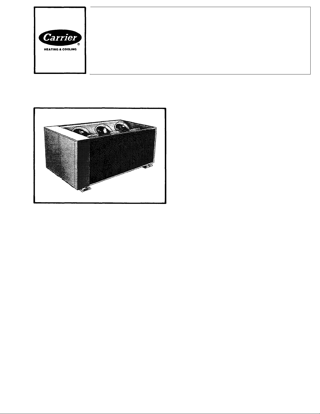
Packaged
Air-Cooled
Flotronic™
Liquid Chiller
Nominal 60-Ton Capacity
Features
• Unit nominal capacity serves virtually any large com
mercial or institutional air conditioning need or industrial
process cooling requirement.
• High-tech solid-state electronic control circuitry tested
to U.S. Government Space Agency standards.
• Microprocessor control maintains total control over
chiller functions, permitting intelligent control of the
refrigerant cycle.
• Diagnostic module with digital display included to
permit rapid troubleshooting just by pressing a button.
• Electronic expansion valves (EXV) operate down to
ISpsig (103 kPa) pressure differential. (Ordinary ther
mostatic expansion valve typically requires lOOpsig
[690 kPa] differential.) This reduces compressor motor
power requirements and improves the unit EER.
• Flotronic™ chiller provides up to 28% efficiency im
provement over standard 30GB chillers on an annual
basis.
• Additional operating cost savings with precise multiplestep compressor capacity control.
• Multiple compressors and dual refrigerant circuits help
to protect against the possibility of loss of total capacity.
• Semi-hermetic 06E compressors are serviceable in
the field.
30GB060
Designed for outdoor installation to minimize required
mechanical room space.
Air-cooled condenser design saves condenser water
and eliminates cooling tower.
Domestic units will operate to 115 F (46 C).
Protection against freeze-up — low water temperature
cutoff and electric heaters protect cooler.
Available as standard with aluminum fins and copper
tubes for normal applications, or with all-copper coils.
Field-installed accessories
• Demand limit control module (required for remote
ON/OFF control)
• Leaving chilled water temperature reset accessory board
• Sensor kit assembly for outdoor or space temperature
reset of chilled water temperature
• Ground current refrigeration circuit protection
• Discharge and suction pressure gage panel
• Oil pressure switch package includes oil pressure
switches (2) for unit
• Capacity control: accessory electric suction cutoff
unloader
• Motormaster® head pressure control (requires unit
modification for low-ambient operation)
Factory-Installed option (FlOP)
Thermal expansion valves — For those situations where
energy savings of the EXV are secondary and equipment
first costs are most important. With this option, the
electronic expansion valve and controls related to the
EXV function, head pressure control and its related
part-load energy savings, are deleted from unit and are
replaced by thermal expansion valves and liquid line
solenoid valves. Minimum operating ambient for FlOP
TXV-equipped units with standard head pressure control
is 32 F. Contact your Carrier representative for details
on operation at temperatures below 32 F. The FlOP model
continues to have microprocessor features and diagnostic
capability. Standard accessories are useable.
2-87
Form 30GB-1APD
Page 2
Table of contents
Page
Features .............................................................................1
Field-Installed Accessories ...............................................1
Factory-Installed Option (FIOP)......................................1
Model Number Nomenclature ..........................................2
Physical Data....................................................................2
Application Data ............................................................2-6
Selection Procedure
Performance Data
..........................................................
...........................................................
7-9
Model number nomenclature
30GB 060 - 6
30GB-AIR-COOLED
OUTDOOR LIQUID CHILLER
UNIT SIZE (approximates chiller capacity in tons)
Page
Dimensions .................................................................... 10
Mounting Weights ......................................................... 10
Electrical Data ............................................................... 11
Controls ....................................................................... 11,12
Control Sequence
..........................................................
13
Typical Installation ........................................................ 14
6
Guide Specifications
....................................................
— 1 575-3-60
— 5 208/230-3-60
— 6 460-3-60
15,16
Physical data
MODEL 30GB 060
APPROX OPER WT - lb 4900
REFRIG CHG — lb
Circuit 1 65
Circuit 2 85
COMPRESSORS, Type...Rpm Reciprocating,
(No.) Circuit 1* (1) 6275
(No.) Circuit 2 (1) A299
Capacity Control Steps 4
Circuit 1 (%) 43
Circuit 2 (%) 57
Minimum Step Capacity (%)
CONDENSER FANS — Type Propeller, Direct Drive
Fan Speed — Rpm 1080
No. Biades...Diameter-in.
Circuit 1/Circuit 2 4...26/3 ..30
No. Fans...Total kW
Totai Airfiow — Cfm
CONDENSER COiLS — Type
Tubes (Copper), OD-in. '/2
Fins/in. Circuit 1/Circuit 2 14 2/15.0
No. Rows Circuit 1/Circuit 2 %
Face Area (sq ft) Circuit 1 57 5
Max. Working Pressure
Refrig psig
COOLER — No. ...Type
Modei 10HA400— 824
No. Refrigerant Circuits 2
Net Water Volume — Gal.
(includes nozzles)
Max. Working Press. — psig Refrigerant Side-235,
WATER CONNECTIONS MPT
Inlet and Outlet — in. 3
Drain — in. FPT
*6 prefix indicates one electric unioader.
"A” prefix indicates no unloader.
tCopper fins aiso avaiiabie
Circuit 2
Semi-Hermetic 1750
29
6. 1 92
46500
Plate Fins (Aluminumf)
57.5
450
One...Direct Expansion,
Shell & Tube
17 7
Water Side-150
%
Application data
Leveling unit
Unit must be level when installed to ensure proper oil
return to the compressors.
While most outdoor locations are suitable for 30GB
units, the roof is a common site that presents a problem
if roof has been pitched to aid in water removal. To
assure proper oil return, be sure that unit is level,
particularly in its major lengthwise dimension, as com
pressor oil return piping runs in that direction.
It should be determined prior to installation if any
special treatment is required to assure a level installation.
Cooler temperature
1. Maximum leaving chilled water temperature (LCWT)
for Model 30GB is 70 F (21 C). Unit can start and pull
down with up to 95 F (35 C) entering water tempera
ture due to MOP (maximum operating pressure)
feature of the expansion valve. For sustained opera
tion, it is recommended that entering water temperature
not exceed 85 F (29.4 C).
2. Minimum LCWT for standard Model 30GB is 40 F
(4.5 C). It is permissible to use a standard micro
processor-controlled Flotronic chiller with leaving
water temperatures in the range of 34 F (1°C) to 39.9 F
(4.4 C) only if a protective brine solution (20% antifreeze
solution, or greater) is used and microprocessor dip
switch is properly set. (See Controls and Trouble
shooting book for further information.) Special order
medium temperature brine units must be ordered for
operation with leaving water temperatures in the range
of 34 F (1°C) to 15 F (-9C). For ratings below 40 F
4.5 C) LCWT, contact your local Carrier representative.
Page 3
Application data (cont)
MINIMUM COOLER WATER FLOW RATES
AND MINIMUM LOOP VOLUME
UNIT 30GB
060 67
NOTES.
1. Minimum flow based on 1 5 fps veiocity in cooier without special
cooler baffling
2. Minimum Loop Volumes:
Gallons = V X ARl Cap (tons)
APPLICATION
Normal Air Conditioning
Process Type Cooling
Low Ambient Unit Operation
MINIMUM
FLOW (1)
Gpm ft of water
PRESSURE
DROP
3.8
MINIMUM
VOLUME (2)
Gallons
180
Leaving water temperature reset
Accessory board* may be installed in 30GB chillers to
provide reset of LCWT in constant water flow systems.
Reset reduces compressor power usage at part load when
design LCWT is not necessary. Humidity control should
be considered since higher coil temperatures resulting
from reset will reduce latent heat capacity. Three reset
options are offered;
From return water temperature* — Increases LCWT
temperature set point as return (or entering) water tem
perature decreases (indicating load decrease). Option
may be used in any application where return water provides
accurate load indication. Limitation of return water reset is:
LCWT may only be reset to value of design return water
temperature. Return reset is the simplest of 3 reset acces
sories available, as return water sensor is already installed.
From outdoor temperature* — Increases LCWT as
outdoor ambient temperature decreases (indicating load
decrease). This reset should be applied only where outdoor
ambient is an accurate indication of load. An accessory
thermistor is required.
From space temperature* — Increases LCWT as space
temperature decreases (indicating load decrease). This
reset should be applied only where space temperature is
an accurate indication of load.
For details on applying a reset option, refer to 30GB
Controls and Troubleshooting Instructions.
*Obtain ordering part numbers from current price pages.
c. Special cooler baffling is required to allow minimum
flow rate to be reduced 12%.
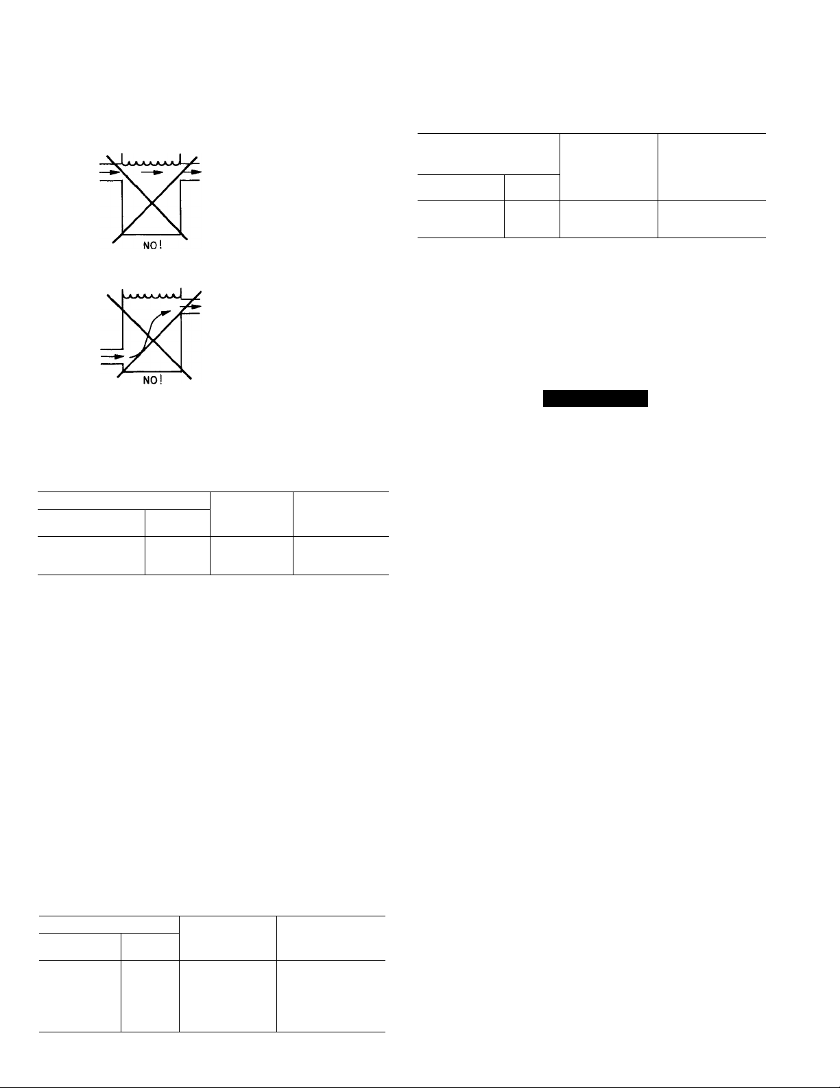
CHILLER COOLER
RECIRCULATION
SUPPLY
RETURN
Maximum cooler flow (> 5 gpm/ton or < 5 F range
[>0.09 L/s . kW or <2.7 C range]) results in practical
maximum pressure drop through cooler.
a. Return water may bypass the cooler to keep pressure
drop through cooler within acceptable limits. This
permits a higher AT with lower water flow through
cooler and mixing after the cooler.
b. Special cooler baffling is available by special order,
to permit a cooler flow rate increase of 10%.
CHILLER COOLER
BYPASS
SUPPLY
RETURN
Cooler flow range
Ratings and performance data in this publication are
for a cooling range of 10°F or 6°C. Flotronic^" chillers with
microprocessor control may be operated at a different
temperature range provided flow limits are not exceeded.
For minimum flow rates, see Table. High flow rate is limited
by pressure drop that can be tolerated. If another range is
used, apply LCWT correction as given in selection example.
Minimum cooler flow (maximum cooler temperature
range) for standard units is shown in Table. When gpm
(L/s) required is lower (or range higher), follow recom
mendations below:
a. Multiple smaller chillers may be applied in series, each
providing a portion of the design temperature range.
b. Cooler water may be recirculated to raise flow rate.
However, mixed temperature entering cooler must
be maintained a minimum of at least 5°F (2.8°C) above
the leaving chilled water temperature.
Variable cooler flow rates may be applied to a standard
30GB chiller. Unit will, however, attempt to maintain a
constant leaving chilled water temperature. In such cases,
minimum flow must be in excess of minimum flow given in
Table and flow rate must change in steps of less than 10%
per minute. Apply 6 gallons per ton (6.5 liters per kW) water
loop volume minimum if flow rate changes more rapidly.
Water loop volume — In circulation must equal or
exceed 3 gallons (11.4 liters) per nominal ton of cooling
(3.25 liters per kW) for temperature stability and accuracy
in normal air conditioning applications. (For example, a
30GB060 would require 180 gallons in circulation in system
loop — see Table.) For process jobs where accuracy is
vital or for operation at ambient below 32 F (0°C) with low
unit loading conditions, there should be from 6 to 10 gallons
Page 4
Application data (cont)
per ton (6.5 to 10.8 liters per kW). To achieve this volume,
it is often necessary to install a tank in the loop. Tank
should be baffled to insure that there is no stratification
and that water (or brine) entering tank is adequately mixed
with liquid in the tank.
GOOD
GOOD
Cooler fouling factor used to calculate tabulated ratings
was 0.0005 ft2. hr. °F/Btu (0.000088 m^. K/W). As fouling
factor is increased, both unit capacity and compressor
power decrease. Standard ratings should be corrected
using following multipliers:
FOULING FACTOR
ENGLISH
((F . hr. °F/Btu)
0.0005 0.000088 1.00
0.001 0.000176 0.97
0.002 0.000352 0.91
SI
(m*. K/W)
CAPACITY
MULTIPLIER
COMPRESSOR
POWER
MULTIPLIER
1 00
0.98
0.91
Cooler protection in form of ethylene glycol (or other
suitable brine) is recommended when operating in areas
which experience temperatures below 32 F (0°C) to
protect cooler should there be a loss of cooler heater
power. Even though unit cooler is protected with insula
tion and an electric heater that protects the cooler down
to 10 F (-12 C), it does not protect water piping external
to unit. Use only antifreeze solutions approved for heat
exchanger duty. Use of automotive antifreezes is not
recommended because of the fouling that can occur once
their relatively short-lived inhibitor breaks down.
Draining cooler and outdoor piping is recommended if
system is not to be used during freezing weather condi
tions. See section below for low-ambient operation.
Condenser
Altitude correction factors must be applied to standard
ratings at altitudes above 2000 ft (610m) using following
multipliers:
ALTITUDE
ENGLISH
(ft)
0
2000
4000 1220
6000
8000 2440
10000
SI
(m)
0 1 00
610 0 99
1830 0,97
3050 0.95
CAPACITY
MULTIPLIER
0 98
0.96
COMPRESSOR
POWER
MULTIPLIER
1.00
1.01
1.02
1.03
1.04
1.05
Condenser airflow restrictions will affect the unit
capacity, condenser head pressure and compressor
power input. Correction factors to be applied for external
static restrictions up to 0.2 in. wg (50 Pa) are shown below.
EXTERNAL
STATIC
RESISTANCE
ENGLISH
(in. wg)
0.0 0.0
0.1 25
0.2 50 0 968 1.03
SI
(Pa)
CAPACITY
MULTIPLIER
1 00 1.00
0 986
COMPRESSOR
POWER
MULTIPLIER
1 01
High-ambient temperature — Standard 30GB chillers
can operate to 115 F (46 C) ambient temperature.
Low-ambient operation
Flotronic^“ 30GB chillers with electronic expansion valves
(EXV) will start and operate at ambients down to 0°F
(-18 C) with following field provisions:
Wind baffles must be added for operation below 32 F (0°C).
A WARNING
Operation at low ambient is not recommended if
minimum load on chiller is below minimum step of
unloading.
Protection against freeze-up — It is recommended
that field-installed chilled water piping be protected at
lower ambient temperatures by wrapping with field-supplied
heating cable and covering with 2-in. (50-mm) thick closed
cell insulation.
Antifreeze solution must be added to water loop to
protect loop down to 15 F (8 C) below minimum operating
ambient temperature.
For operation of EXV-equipped chillers below 0°F
(-18 C) and for operation of TXV-equipped (factoryinstalled option) chillers below 32 F (0°C), down to -20 F
(-29 C), the Carrier Motormaster® condenser head pres
sure control and its associated components must be
added. Consult your local Carrier representative for
complete details.
Provide sufficient volume in the chilled water loop — At
least 6 gallons per ton of refrigerant (6.5 liters per kilowatt)
is recommended minimum, provided there is a moderate
system load.
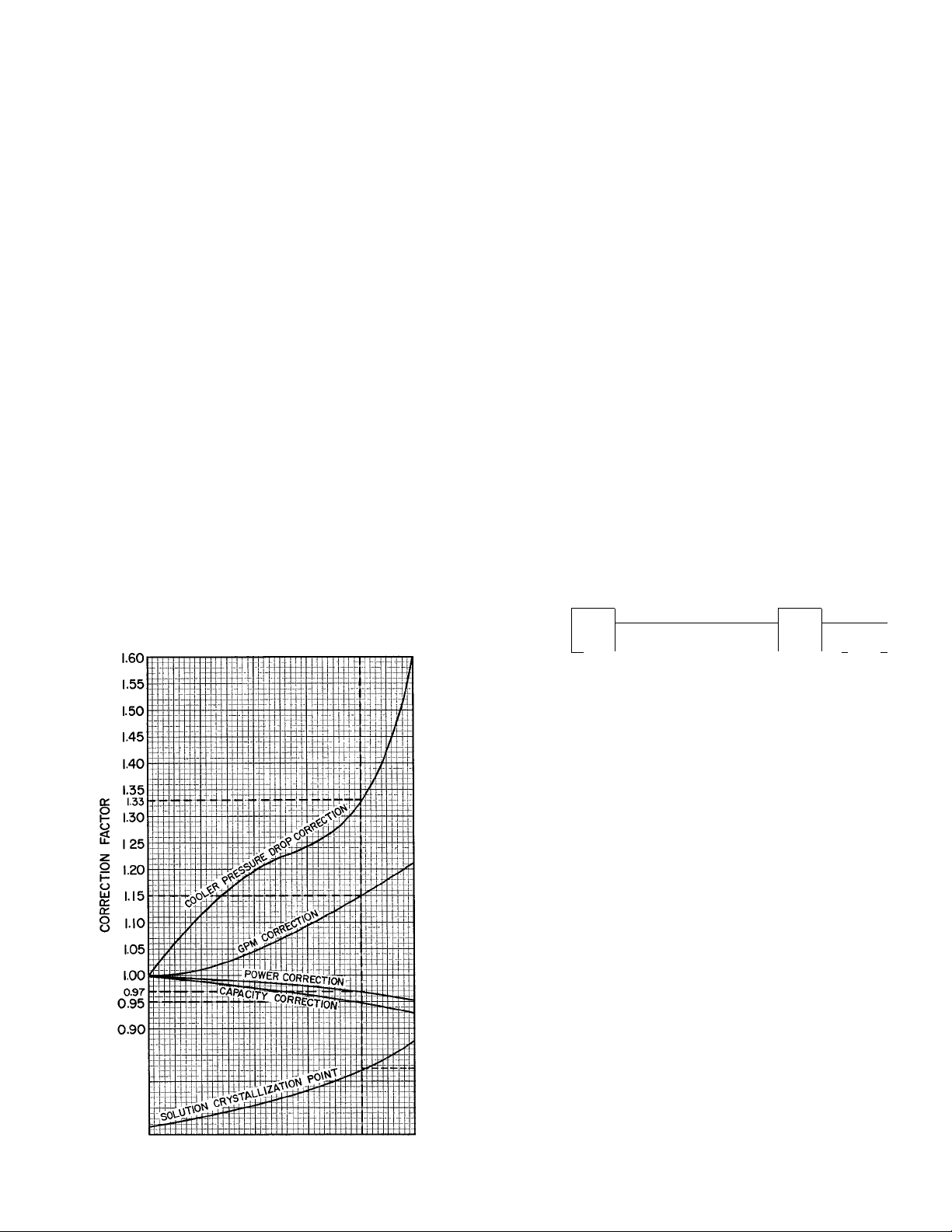
Capacity Correction (Antifreeze)
Ethylene glycol (or other suitable brine) should be used in
installations where subfreezing temperatures are ex
pected. Unit performance data must be corrected for
the addition of ethylene glycol as shown in following
example. Correction factors may be derived from follow
ing curves.
Example: Where a 5 F outdoor temperature is anticipated,
determine concentration of ethylene glycol to protect
system to -10 F ambient temperature at zero flow.
Enter the solution crystallization point curve at -10 F,
read 40% concentration of ethylene glycol is required to
prevent crystals from forming in solution.
Consider the 30GB060 unit from the Selection Pro
cedure (Water) example (refer to correction curves at
40% solution).
Page 5
Application data (cont)
Correct unit capacity — On glycol performance
capacity correction curve, read 0.95.
Corrected capacity = 0.95 x determined capacity
- 0.95 X 61.3
= 58.2 tons
Correct chilled water flow — On the gpm correction
factor curve, read 1.15.
Chilled water flow (at corrected capacity)
24 X corrected capacity
temperature rise
24 X 58.2 tons
14 F
99.8 U.S. gpm
= U.S. gpm
Chilled water flow (40% solution) = 1.15x99.8
= 114.7 U.S. gpm
Correct cooler pressure drop — On cooler pressure
drop correction curve, read 1.33.
On cooler pressure drop curve, for 114.7 gpm, read
PD = 10 ft water gage. The pressure drop for 40% solution =
1.33 X 10.0 = 13.3 ft water.
Correct compressor power input (kW) — On power
correction curve, read 0.97 correction factor at 40%
EG concentration.
Power input from Selection Procedure example
= 71.1 kW.
Corrected power input = 0.97 x 71.1 = 68.9 kW.
Oversizing chillers
Oversizing chillers by more than 15% at design conditions
must be avoided as the system operating efficiency would
be affected adversely (resulting in greater/excessive
electrical demand). When future expansion of equipment
is anticipated, it is strongly recommended that a single
chiller be installed to meet present load requirements
and a second chiller added to meet the additional load
demand.
It is also recommended that the installation of 2 smaller
chillers be considered where operation at minimum load
is critical. The operation of a smaller chiller loaded to a
greater percent of minimum is preferred to operating a
single chiller at or near its minimum recommended value.
Multiple chillers
Where chiller capacities greater than 200 tons (703 kW)
are required, or where stand-by capability is desired,
chillers may be installed in parallel. Units should be of
equal size to ensure balanced water flows. Where a large
temperature drop (>25F [13.9 C]) is desired, chillers
may be installed in series. Water temperature sensors
need not be moved for multiple chiller operation. A 10-ft
(3-m) separation is required between units for airflow,
and a 6-ft (1.8-m) distance is required from units to
obstructions. See figure. See Physical Data for service
clearances.
ETHYLENE GLYCOL PERFORMANCE
CORRECTION FACTORS AND SOLUTION
CRYSTALLIZATION POINTS
(F)
-40
-20
-10
0
+20
40
10 20 30 40
% CONCENTRATION (BY WEIGHT)
ETHYLENE GLYCOL
50
(C)
r-40
c -30
-20
-10
0
(3m) (I.Sm)
10 FT 6 FT
* MINIMUM
////// //
MULTIPLE UNIT SEPARATION
MINIMUM
Electrical/utility interests
Energy management — See 30GB Controls and Trouble
shooting manual and accessory installation instructions
for details.
Demand limiting (also called load shedding) — When
utilities demand for electricity exceeds a certain level,
loads are shed to keep electricity demand below a pre
scribed maximum level. Typically, this happens on hot
days when air conditioning is most needed.
Load shedding must be done intelligently. Demand
may be limited on Model 30GB by resetting water tem
perature, or by using a demand limit accessory that
unloads the chiller to a given predetermined percent of
the load. Both features require signal from an intelligent
central control. Do not cycle demand limiter for less than
10 minutes on and 5 minutes off.
Duty cycling cycles electrical loads at regular intervals
regardless of need. This reduces electrical operating
costs of a building by “fooling” demand indicating
devices. Duty cycling of compressors or fans is not
recommended since motor winding and bearing life
suffer from constant cycling.
Page 6

Application data (cont)
Time clock shutdown (or other controlled shutdown
not associated with leaving chilled water temperature)
requires use of accessory demand limit control module.
Second step of the demand limit control (0-50% of
capacity) is set for 0 (zero) capacity. This allows unit to
go through a normal pumpout cycle at shutdown.
Part-wind start
Not generally required on 30GB chillers due to use of
multiple compressors allowing smaller electrical load
increments, but is available if required. Maximum
instantaneous current flow (see ICF in Electrical Data)
should be used in determining need.
Vibration isolation
Compressors are spring isolated,
isolation is not generally required.
External vibration
Hot gas bypass usage (units with TXV only)
Hot gas bi^pass usage, while frequently specified, is not
normally recommended because it results in equipment
being applied below its normal application range. Before
applying hot gas bypass, it is recommended that use of 2
machines be considered, including one that can be run at
the system minimum load without addition of hot gas
bypass. In those instances where there is no alternative,
it is recommended that the appropriate hot gas bypass
package can be used with the factory option TXV unit.
Medium temperature brine application — Application
of 30GB outdoor chillers for brine duty within the 39.9 F
to 34 F (4.4 C to 1°C) range is possible with proper field
change of control configuration. Application in the
range 34 F to 15 F (1°C to -9.4 C) requires 30GB unit
with factory modification.
Selection procedure
I Determine unit size and operating conditions
required to provide specified capacity at given
conditions:
Capacity required............................................. 60 tons
Leaving chilled water temperature ....................... 45 F
Chilled water temperature rise
Condenser entering air temperature (CEAT) .. 95 F
Loop volume
Ratings are based on 10 F rise and are suitable for rise
from 5 F to 15 F without adjustment. In this case,
however, greater accuracy is desired.
II Correct LCWT for 14 F cooler water tempera
ture rise.
Enter correction curve at 14 F and read a correction
of 0.3 F. Corrected LCWT is, therefore, 45 + 0.3 = 45.3 F.
III Determine capacity, unit size and power input.
Enter rating table at given CEAT and LCWT —
respectively 95 F and 45 F.
Read down capacity column until the capacity nearest
to but higher than specified required capacity is
reached. In this case, 60.9 tons is delivered by a
30GB060. Interpolate between 45 F and 46 F to find
.............................................
.............................
230 gallons
14 F
determined capacity and power input at corrected
LCWT (45.3 F). Values are:
Capacity
Power input
IV Calculate corrected cooler water flow.
Water _ 24 x corr capacity in tons
flow temperature rise F
V Calculate the cooler pressure drop.
Enter cooler pressure drop curve at the corrected
flow rate (105.1 U.S. gpm) and read, for the 30GB060,
a pressure drop of 9 ft of water.
VI Check loop volume and cooler water flow rate.
Minimum loop volume, from application data, is
180 gallons for 30GB060. Therefore, given volume of
230 gallons is satisfactory. Minimum water flow rate,
from application data, is 67 gpm for 30GB060. Flow rate
of 105.1 gpm is well above minimum required.
.........................................................
.....................................................
U.S. gpm
24 X 61.3
14
105.1 U.S. gpm
61.3 tons
71.1 kW
Page 7

Performance data
STANDARD RATINGS* — REFRIGERANT 22
COMPRESSOR
POWER INPUT
(kW)
(tons)
59 7
CAPACITY
(Btuh)
716,400 68.4
UNIT
30GB
060
*Per ARl Standard 590-81, Section 7 2
NOTE: 95 F condenser entering air temperature; 54 F entering/
44 F leaving cooler water; 0 0005 № • hr • °F/Btu cooler fouling
allowance.
30GB060 PART-LOAD EFFICIENCY (EXV UNITS ONLY)
BUILDING COOLING LOAD PROFILE
FAN POWER
(kW)
7.81
COOLER WATER
PRESSURE DROP
(ft water)
13.7
MINIMUM CAPACITY STEP (%)
MODEL 30GB
060 29 29
‘Includes factory-furnished unloader where applicable.
fWith field-installed accessory unloader
NOTE: See Table of Capacity Control Steps.
STANDARD UNIT‘ WITH ACCESSORY
ENERGY EFFICIENCY
RATIO
(EER)
94
EER
Capacity (Btuh)
Input Power (W)
STANDARD UNIT
UNLOADERt
(17.8) (12 1) (-6.5) (-1) (4.5) (10) (15.5) (21) (265)02.9) (37.9) (C)
OUTDOOR TEMPERATURE
1
1 I ZERO LOAD AT 0°F (-17.8 C) OPT
OUTSIDE
% SYSTEM
FULL LOAD
100
90
80
70 66 5
60 57.0
50 47.5 8.5
40 38.0 3 1
30 28 5
AMBIENT
TEMP
F
95.0
85 5 29.8 10.6
76 0 24.3 11.8
C F
35.0
19.0 13.0
13.9
-2.0
UNIT
EER
9.4
14.2
16.9
21.6 40 62.0 16 7
26.2
I 2 I ZERO LOAD AT 20 F (-6.5 C) OPT
OUTSIDE
% SYSTEM
FULL LOAD
100
90
80 80.0 26 5
70 72.5 22.3
60
50 57.5 14.0
40 50.0 10.0
30 42.5 5.9
ODT — Outdoor Temperature
NOTES:
1 Above efficiency ratings obtained at 54/44 F (12.2/6.7 C) cooler
water; full load at 95 F (35 0).
2 The longer the time operating at low temperatures, the greater the
difference in operating costs favoring a Flotronic™ unit over a
standard TXV unit
AMBIENT
TEMP
F
95 0 35.0 9.4 100
87 5 30.9 10.0
65.0 18 2
C
UNIT
EER
10.5
11.1
11 6
12.6
14.7
16.9
3 I ZERO LOAD AT 40 F (4.4 C) OPT
OUTSIDE
% SYSTEM
FULL LOAD
100
90
80
70
60 73 0
50
30 56.5
AMBIENT
TEMP
C
95 0
89 5
84 0 28.9
78 5
67.5 19 7
35.0
31.9
25.8
22 8
136
UNIT
EER
94
103
11 1
12.0
12 8
142
17.3
20.4
I 4 I ZERO LOAD AT 55 F (12.5 C) OPT
OUTSIDE
% SYSTEM
FULL LOAD
90
80
70
60
50
40
30
Contact your local Carrier representative for a computer analysis
of operating costs.
EER = Energy Efficiency Ratio
Capacity (Btuh)
Input Power (W)
AMBIENT
TEMP
F
95.0 35.0 9.4
91 0
87.0 30.6
83 0 28.3
79.0 26.1 10.9
75 0 23.9 11 2
71 0
67.0 19.3
C
32 8 9.8
21 7
UNIT
EER
10.2
10.6
12.7
14.4
Page 8

Performance data (cont)
TOTAL COOLER PRESSURE DROP (Water Side)
300-
270
240-
210
180-
ISO
120-
90-
75-
•5 60-1
a.
K
45-
o
UJ
5
(f>
UJ
30-
a.
27
24
21
18-
15-
12-
9-
80 90100
COOLER WATER FLOW (6PM)
-T—
3
7 10 15 20
COOLER WATER FLOW (L/S)
CAPACITY CONTROL STEPS
LOADING SEQUENCE A (Note 1)
UNIT 30GB060
Standard
(One Unloader)
Accessory Unloader
Added to
Compressor No. 2
‘Compressor unloaded.
NOTES:
1. The microprocessor has a random number generator that selects
loading sequence A or B, which in turn determines the com
pressor circuit that is energized first. This evens out operating
hours on each circuit over an extended period of time
CONTROL
STEPS
1 29 1
2
3 72 2
4
1
2
3
4
%
DISPLACEMENT
(Approximate)
43
100.0 2
38
66
85
100
No.
of
Compr
1
1
2
2
2
Operating
No.
of
Cyl
4
6
10
12 1 2
4
8
10
12
Compressor No.
Circuit 1 Circuit 2
1*
1
1*
1*
1*
1*
1
If unit operation is anticipated with system load below minimum
unloaded capacity of chiiler:
a. Consider using 2 smaller units in place of larger unit.
b. Increase water loop volume to ensure adequate run time (see
Application Data).
600 TOO 1000
30
LOADING SEQUENCE B (Note 1)
No.
of
Compr
—
—
2
2*
2
2
—
—
—
1
2
2
2
No.
of
Cyl
—
— — —
—
—
4
8
10
12
800
—I
-----
1—I
40 50 60
Operating
Compressor No.
Circuit 1
__ __
— —
—
1*
1
1
Circuit 2
—
2*
2*
2*
2
Page 9

Performance data (cont)
COOLING CAPACITIES - 30GB060
CONDENSER ENTERING AIR TEMPERATURE (F)
LCWT
SDT kW
113.2 63.7
114.3 65.1 145.7
121.8 74 6 187.0
125.1 78.5
40
42
44
45
46
48
50
55
60
Cap.
58.5
60 9
63 4 115.3 66.5 151.7
64.6 115.9 67.2 154.7
65.9 116.5 67.9 157.8
68.4 1176
71.1 118.8 70.8 170.4
77.9
85.2
LCWT
Cap.
40
42
44
45
46
48
50
55
60
Cap.
Flow Rate
kW
LCWT
PD
SDT
NOTES:
Ratings appiy to units with electronic or thermai expansion vaives.
1
Aii ratings are based on.
2
a. A cooler chilled water temperature rise of 10° F. When greater
b. A fouling factor of 0.0005 in the cooler,
c Refrigerant 22.
3 When a corrected LCWT is used, cooler pressure drop must also
be corrected for new LCWT :
a Enter rating tabie for corrected LCWT By interpolation,
b Calculate corrected flow rate through the cooler.
c. Enter cooier pressure drop curve at corrected fiow rate and
4. When chiiled water temperature rise is iess than 5°F, high fiow
rate will normally be accompanied by an excessive pressure drop.
In such cases, contact your Carrier representative for speciai
selection of a cooler with wider baffle spacing.
51.6 131.1
53.8
56.1
57.2 133.7
58.4
60.8 135.3
63 2
69 5
76.2
accuracy is desired, correct design LCWT, before entering
rating tabies, by reference to the LCWT correction curve.
determine corrected capacity (tons) and power input (kW) to
compressor at its rated voltage,
24 X capacity in tons
“ X X .—“US Qpm
temperature rise F
read pressure drop
SDT kW
132.1
133 2
134 2 75.1 139.9 124
136.4
139.3
142.4 87.8 183.1 20.7 —
Cooling Capacity Tons of Refrigeration
U S Gpm
Compressor Power input
Leaving Chilied Water Temperature (F)
Pressure Drop (Ft of Water)
Compressor Saturated Discharge Temperature (F)
85
Cooler
PD
Cap.
66.5
75.8
122.0 71.4
126 2
129.4 81.0
69.4
Flow
Rate
139 9 124 56 7 1177
164 0
204 6 25.6 82 9
13.4 59.1 118.7
144 61.5 119.8
15 0 62 7 120 3
15 6 64.0 120 9
16.8
18.0 69 1 123.2
21.5
CONDENSER ENTERING AIR TEMPERATURE (F)
105
Cooler
Flow
Rate
70.0 123 3
71.7 128 7
73 4 134 2
74.3 137.0
76 9 145.7 13.4
78.7
83.2
151 6 144 59 2
166 8 17.3
10.5 50 2
11 4 52.4
11 9 53 5
Cap. SDT
PD
9.7 48.1
140.0
141.0
142.0
54 6
56 9 144.1
142.5
143.1 78.2
145.2
— — —
LEGEND
SDT
— —
90
Cooler
kW
65.4
66.9 141.4
68.4 147.2
69.1 150.2
69 9 153 2 14.7 62.1
72 9 165.7 17 1
76 9 182.0
Flow
Rate
135.6 11 7 55 0 122.1
159 4 15.9
199 3
Cap.
PD
12.6 57.3 123 2 68.6 137.1
13.6 59.7 124.2 70.1
14.2 60.9 124 8
64 6 126.5 73.3 154 8 15.0
20 5 73.8 130.6 79.1 177 0 19.4
24.3 80.7 133 8
67.1 127 6
115
Cooler
kW
72 6 114.9 8.5
74 4 120.1 92
76.3 125 4
77.3 128 1 10.5
80.1 136.3
82.1 142.0 12.7
Flow
Rate
PD
10 0
130 8 10.9
11 8
—
— —
—
95
Cooler
SDT
125.3 71 7 148.7 13.9
kW
Flow
Rate
131 5
67.0
142 9 129
70.9 145 8
161.0
74.9
83 4
193.9 23.1
PD
11.0
11.9
13 4
16 2
5 lO i5 20
COOLER CHILLED WATER TEMPERATURE RISE (F)
Above 10F, ADD correction to design LCWT, below 10 F, SUBTRACT
Page 10

Dimensions
DIMENSIONS
DIM.
A
B
C
D
E
F
G
H
J
ft-in.
(mm)
UNIT
30GB060
13-7%
(4162)
11-3
(3429)
12-5%
(3797)
10-0%
(3061 )
5-8%2
(1730)
5-3%
(1619)
4-6%
(1387)
7-6
(2286)
5-0
(1524)
TOP VIEW
'AMER. STD.
ST PIPE THO.
4"-(070 UNIT)
COOLER END VIEW
Space for service and airflow.
Mounting weights (approximate) lb
WEIGHT DISTRIBUTION
SUPPORT UNIT
POINTS
1
2 1528
3 922
4 872
30GB060
1578
SIDE VIEW
10
Page 11

Electrical data ~ 60 Hz
UNIT
460
575
Volts
Supplied*
Min Max
187 254
414
518 632
MCA
508 155
342
128
MORA
(Fuse)
500 846 119
225 415 53 73
125
30GB
Nameplate
060
NOTE: As shipped, all units are XL (across the line) start.
•Units are suitable for use on electrical systems where voltage
supplied to the unit terminals is not below or above the listed
minimum and maximum limits.
f30GB060 has 2 compressors.
jaOGBOeO has one FOB for all fans.
GENERAL ELECTRICAL NOTES:
1 Unit listings are:
UL — Underwriters Laboratories: 30GB060
2. Electrical data based on unit conforming to ARl Standard 590,
Section 8.1. Maximum Loading Conditions (115 F ambient at
-10% voltage)
3. All units have single-location power connection to simplify fieldpower wiring Main power must be supplied from a field-supplied
fused disconnect. Unit must be properly grounded.
4. Control circuit power must be supplied from a separate source
through a field-supplied fused disconnect. (See Note 9.)
5. Crankcase and cooler heaters are wired into the control circuit
so they are always operable as long as the control circuit power
supply disconnect is on, even if any safety device is open or the
unit CN/CFF switch is off.
208-230
ICF
335
RLA (ea)
45 59
COMPRESSORSt
Compressor No.
2
1
158.5 506 690
6. Heaters are wired ahead of the control circuit fuse; thus, they are
7. Cn all voltages, 30GB060 has one terminal block, with 3 con
8. Maximum incoming wire size for each terminal block is 500 MCM.
9. Amperage required for control circuit is as follows:
10. Power draw of control circuits includes both crankcase heaters
LRA (ea)
1
253 345
176 276
protected by the overcurrent protective device in the control
circuit power supply.
ductors from the fused disconnect.
UNIT
30GB
060
and cooler heaters Each compressor has a crankcase heater
that draws 200 watts of power
Cooler heaters: 060 - 360 watts — band heaters (360 watts total).
Total MTA
CB h O.
2 1
166 222 6 (1)
73 90 6 (1)
63 82 6(1)
POWER
SUPPLY
208/230-3-60
460-3-60
575-3-60
2
Total
Fans
(Ph)
FAN MOTORS*
FLA (ea)
Fan No.
3,4,5,6
1,2
4.6 7 7
2.3 3.3
1.8 2.6
CONTROL
CIRCUIT
Power
115-1-60
115-1-60
115-1-60
MTA
(FCB)
Amps
15
15
15
35
18
14
Controls
Microprocessor — Microprocessor controls overall
unit operation. Its central executive routine controls a
number of processes simultaneously. These include
internal timers, reading inputs, A to D conversions, fan
control, display control, diagnostic control, output relay
control, demand limit, capacity control, head pressure
control and temperature reset. Some processes are
updated almost continuously, others every 2 to 3 seconds,
and some every 30 seconds.
The microprocessor routine is started by switching
control circuit ON-OFF circuit breaker switch to ON.
(This switch is also used to reset microprocessor should
any safety trip and also functions as circuit breaker for
electronic processor and relay boards.)
When the switch is closed, a 2-minute initialization
routine is begun. During this time, inputs are checked,
EXV and internal constants are initialized and a 20
appears on display. If display button is pushed during this
period, control goes into a 42-step Quick Test routine,
normally used for a readiness check during start-up, or
for service.
Microprocessor controls capacity of chiller by cycling
compressors and unloaders on and off at a rate to satisfy
actual dynamic load conditions. Control will maintain
leaving water temperature set with dial on display board
through intelligent cycling of compressors. Accuracy will
depend on loop volume, loop flow rate, load, outside air
temperature, number of stages, and particular stage
being cycled off. No adjustment for cooling range or
cooler flow rate is required, because the control auto
matically compensates for cooling range by measuring
both return water temperature and leaving water
temperature. This is referred to as leaving water tem
perature control with return water temperature
compensation.
The basic logic for determining when to add or remove
a stage is a time band integration of deviation from set
point plus rate of change of leaving water temperature.
When leaving water temperature is close to set point and
slowly moving closer, logic prevents addition of another
stage. If leaving water temperature is less than 35 F
(1.7 C) for water, or 6°F (21°C) below the set point for
brine units, the unit is shut off until the water tempera
ture goes 6°F (3.3°C) above the set point, to protect
against freezing.
If l°F/minute (0.6°C/minute) pulldown control has
been selected (factory setting), no additional steps of
capacity will be added as long as difference between
leaving water temperature and set point is greater than
4°F (2.2°C) and rate of change in leaving water tempera
ture is less than l°F/minute (0.6°C/minute).
If it has been less than 90 seconds since the last capacity
change, compressors will continue to run unless a safety
trips. This prevents rapid cycling and also helps return oil
during short on periods.
Where available (requires accessory unloaders on some
units), 2 sequences are used to obtain circuit lead-lag
operation, which evens out compressor operating hours.
First, as unit turns on, microprocessor functioning as a
random number generator, determines which circuit will
start first. Also, when decreasing from maximum stage,
control will again randomly select which circuit to run
longest.
The control also performs other special functions
when turning on or off. When a circuit is to be turned off,
EXV is closed first and compressor is run for an additional
10 seconds to pump out refrigerant that was in the cooler.
Again, at start-up, if compressor hasn’t run in the last
15 minutes, EXV is held closed for 10 seconds while
11
Page 12

Controls (cont)
compressor runs to pump out any refrigerant that has
migrated to the cooler. The oil pressure switch is bypassed
for one minute during start-up and for 45 seconds during
normal operation.
Thermistors — Eight thermistors are used for tempera
ture sensing inputs to microprocessor. (A ninth [TIO]
may be used as a remote temperature sensor for optional
LCWT reset.)
T1 Cooler leaving chilled water temperature
T2 Cooler entering water (return temperature)
T3 Saturated condensing temperature — Circuit #1
T4 Saturated condensing temperature — Circuit #2
T5 Cooler saturation temperature — Circuit #1
T6 Cooler saturation temperature — Circuit #2
T7 Return gas temperature entering compressor
cylinder — Circuit #1
T8 Return gas temperature entering compressor
cylinder — Circuit #2
TIO Remote temperature sensor (accessory)
The microprocessor uses these temperatures to control
capacity, fan cycling and electronic expansion valve
(EXV) operation.
Electronic expansion valve (EXV) — To control flow
of refrigerant for different operating conditions, EXV
piston moves up and down over slot orifices through which
refrigerant flows to modulate size of opening. Piston is
moved by a stepper motor through 760 discrete steps. The
piston is repositioned by microprocessor every 3 seconds.
The EXV is used to control superheat in compressor.
Two thermistors in each circuit (T5 and T7/T6 and T8) are
used to determine superheat. One thermistor (T5/T6) is
located in cooler and other (T7/T8) in compressor after
motor in the gas passage entering the cylinders. The EXV
is controlled to maintain superheat entering pistons at
approximately 15 F (8.3 C) to20F (11.1 C), which results
in slightly superheated refrigerant leaving cooler.
Both on shutdown and start-up, unless compressor has
run in last 15 minutes, compressor runs for 10 seconds,
while EXV is closed and removes refrigerant from cooler.
These pumpout cycles minimize amount of excess
refrigerant that can go to compressor on start-up and cause
oil dilution which would result in eventual bearing wear.
The microprocessor software is programmed so that
EXV functions as an MOP. (maximum operating pressure)
valve, limiting the suction temperatures to 55 F (12.8 C).
This makes it possible to start unit at high water tempera
tures, up to 95 F (35 C), without overloading compressor.
Another feature that is factory set (which may be eliminated
in the field by repositioning a dip switch on the micro
processor) limits rate of pulldown to 1°F (0.6°C) per minute
thereby reducing the kW demand on start-up.
Accessory controls — Demand can be further limited
by keeping a selected number of compressors from
turning on by utilizing demand limit control accessory.
This interfaces with microprocessor to control unit so
that chiller’s kW demand does not exceed its setting.
It is activated from an external switch.
Microprocessor is programmed to accept various
accessory temperature reset options, based on return
water temperature, outdoor temperature, or space
temperature, that reset the LCWT. An accessory
thermistor (TIO, above) is required if outdoor tempera
ture or space temperature reset is elected.
Compressor protection and control system (CPCS)
(30GB060) — Compressor protection boards are used
to control and protect compressors. One board is used
for each compressor to control compressor contactor(s)
and crankcase heater(s) in response to a command from
microprocessor. The board also provides compressor
ground current protection, shutting off compressor if a
2 to 3 ampere ground current is sensed by a toroid around
the compressor power leads. A high-pressure protector
and a discharge gas temperature protector are connected
in series with CPCS board, so that if they open, compressor
stops. Microprocessor senses this through feedback
switch input.
The CPCS control system is available as an accessory
on 30GB060. The 30GB060 unit is factory equipped with
a control relay that operates same as CPCS except that
ground current refrigerant circuit protection is not
provided.
Complete electronic control system contains several
additional components.
Relay board — Relay board, connected to microprocessor
by a ribbon cable, drives all of 24-v, 115-v, or 230-v loads.
Relays control compressors, fans, and unloaders, if used.
Display board — Display board, also connected to
microprocessor by a ribbon cable, is used to communicate
with operator. In addition to leaving water set point
potentiometer, board contains 2-digit LED display. The
LED display is normally off after initialization period,
to extend its life. Pressing display button will result in
LED displaying the appropriate overload or status code.
If this is done, display will show from one to 3 codes
alternating every 2 seconds, as follows:
CODE
1. 0-12
STATUS
Capacity stage
Number of stages in operation
2. 20-24
20
21
22
24
3. 51-87
Operating Mode
Initialization
Temperature Reset
Demand Limit
Pulldown Control
Overload Codes
Alarm light/circuit energized.
NOTE: These codes take priority.
51-58
59,60
61
63,64
65
70
71-80
81-87
Compressor fault
Loss of charge (circuit 1, circuit 2)
Low water flow
Low oil pressure (circuit 1, circuit 2)
Low water temperature
Illegal configuration
Thermistor failure
Reset/Set Point/Limit Failure
These codes are summarized on a chart in each unit’s
control box, and are described in detail in the Controls
and Troubleshooting book.
12
Page 13

Control sequence
Off cycle — During unit off cycle, crankcase and, if
ambient temperature is below 36 F (2 C), cooler and
control box heaters are energized. Electronic expansion
valves are closed.
Start-up — After control circuit ON/OFF circuit breaker
switched ON, prestart process takes place for 2 minutes,
when microprocessor checks itself and waits for tem
perature to stabilize. First circuit to start may be no. 1 or 2,
(automatic lead/lag feature). The controlled pull down
feature limits compressor loading on start-up to reduce
demand on start-up and unnecessary compressor usage.
The microprocessor limits supply water temperature
decrease (start-up only) to 1°F (0.6 C) per minute.
Capacity control — On first call for cooling, micro
processor starts initial compressor and fan stage on lead
circuit. The electronic expansion valve remains closed
for 10 seconds, permitting a pumpout on start-up. After
pumpout, the valves open and, if necessary, additional
outdoor fans are energized. Crankcase heaters are de
energized when a compressor is started. As additional
cooling is required, lag circuit starts. If further cooling is
needed, compressors are added, alternating between
lead and lag circuits. Speed at which capacity is added or
decreased is controlled by temperature deviation from
set point and rate of temperature change of chilled water.
As less cooling is required, circuits shut down (or
unload) in an order that evens out each circuit’s com
pressor run time. When no further cooling is called for
On each compressor circuit), expansion valve closes and
compressor and fans continue to run while pumping
down cooler.
Low-temperature override feature prevents LCWT
from overshooting the set point and possibly causing a
nuisance trip-out by the freeze protection.
High-temperature override feature allows chiller to
add capacity quickly during rapid load variations.
Demand limit — If applied, unit step controls limit
total power draw of unit to selected point by controlling
number of operational compressors during periods of
peak electrical demand or time clock shutdown. Consult
Accessory Demand Limit Control Module Installation
Instructions for further details.
Reset accessory — If applied, microprocessor compares
either return water, space or outdoor temperature with
the accessory board settings, and adjusts leaving chilled
water temperature appropriately.
Electronic expansion valve and outdoor fan control —
Expansion valve opens and closes on signal from micro
processor to maintain an approximate 20 F (11C)
refrigerant superheat entering the compressor cylinders.
(The compressor motor increases the refrigerant super
heat from the approximate 5 F [3 C] leaving the cooler to
that entering the cylinders.) Outdoor fans (operated by
microprocessor) run to as low an ambient as possible to
maintain a minimum expansion valve pressure differential.
Abnormal conditions (alarm light) — All control safeties
in chiller operate through compressor protection board
or control relay and microprocessor. High-pressure switch
and discharge gas thermostat directly shuts down
compressor(s) through compressor protection board or
control relay. For other safeties, microprocessor (1) makes
appropriate decision to shut down a compressor due to
a safety trip or bad sensor reading (2) energizes alarm light
and (3) displays appropriate failure code on the display.
Chiller holds in safety mode until reset. It then reverts to
normal control when unit is reset.
Safeties include: Oil-pressure switch cuts out if pressure
differential is below minimum. Switch is bypassed on
start-up for 45 seconds. Loss-of-charge switch cuts out if
system pressure drops below minimum. High-pressure
switch cuts out compressors if compressor discharge
pressure increases to 395 psig (2724 kPa). Discharge gas
thermostat opens when discharge gas temperature
exceeds maximum 295 F (146 C). Ground current safety
opens on sensing a current-to-ground in compressor
windings in excess of 2.5 amps. Loss of flow protection
provided by temperature differences between entering
and leaving water temperature sensors. Flow switch is
not required. Freeze-up protection provided by leaving
water temperature sensor if cooler temperature drops
to 35 F (1.8 C). Sensor failures are detected by the
microprocessor.
Diagnostics — Microprocessor may be put through
Quick Test (see Controls and Troubleshooting book)
without additional equipment or tools. Quick Test
confirms microprocessor is functional, informs observer
through LED display the condition of each sensor and
switch in chiller, and allows observer to check for proper
operation of fans and compressor(s).
13
Page 14

Typical installation
NOTES:
1. Wiring and piping shown are generai points-of-connection
guides oniy and are not intended for or to include all details for a
specific installation.
AIRFLOW THROUGH
AIR-HANDLING UNIT
CONTROL WIRING
CHILLED WATER PIPING
ST - STARTER
FD - FUSED DISCONNECT
2. All wiring must comply with applicable local and national codes
3 All piping must follow standard piping techniques. Refer to
Carrier System Design Manual for details.
#
14
Page 15

Guide specifications
1. GENERAL
1.1 Furnish and install complete, factory-assembled
air-cooled reciprocating liquid chiller units of the
type, size and capacity shown on the equipment
schedules. Unit shall be for outdoor use and rated
in accordance with ARI Standard 590 latest edition.
1.2 Equipment schedules and specifications are based
on Carrier Model 30GB060.
1.3 Reciprocating liquid chillers specified in this section
are of the air-cooled single-piece unit packaged type.
1.4 Units shall be of the packaged air-cooled type as
shown on the drawings and consist of a reciprocating
compressor or multiples thereof, direct-expansion
liquid cooler, air-cooled condenser and factory
wiring and piping contained within the unit en
closure. Unit shall contain a complete operating
charge of refrigerant R-22.
1.5 Unit shall contain factory-installed diagnostic
system, capable of indicating status of all safeties
and energizing remote alarm.
1.6 Unit construction shall comply with ANSI B9.1
safety code, NEC (National Electrical Code) and
ASME Code.
1.7 Unit shall be capable of starting with up to 95 F
(35C) entering water temperature to the cooler.
1.8 Unit shall control leaving water temperature
±
_____
^F (
____
^C) from design point.
1.9 Unit shall be listed with UL.
2. UNIT CASING
2.1 Unit shall be enclosed in a galvanized steel casing,
zinc phosphatized, and coated with a baked enamel
finish, capable of withstanding Federal Test Method
Standard No. 141 (Method 6061) 500-hour salt
spray test.
3. COMPRESSOR
3.1 Each compressor shall be of the reciprocating
serviceable hermetic type only, and shall be
equipped with an automatically reversible oil pump,
operating oil charge, suction and discharge shutoff
valves, and shall be factory mounted on spring
vibration isolators.
3.2 Compressor motor shall be cooled by suction gas
passing around motor winding and shall be thermally
protected. Manual restart shall be required after
stoppage due to thermal and pressure overload.
3.3 Each compressor shall be equipped with an insert
type crankcase heater factory sized to control oil
dilution during shutdown.
3.4 Compressor speed shall not exceed 1750 rpm
(29.2 rps).
4. COOLER
4.1 Cooler shall be shell-and-tube type, with removable
heads. Seamless copper tubes shall be rolled into
tube sheets.
4.2 Cooler shall be tested and stamped in accordance
with ASME code for refrigerant side working
pressure of 235psig (1620 kPa) and a minimum
water side working pressure of 150 psig (1034 kPa).
4.3 Shell shall be insulated with a minimum of 3/4-in.
(19-mm) closed cell polyvinyl chloride (PVC) foam
insulation of maximum K factor 0.28. Heaters along
the shell, under the insulation, shall protect cooler
against freeze-up down to 10 F (-12 C).
4.4 Cooler shall have 2 independent direct-expansion
refrigerant circuits for all models.
5. CONDENSER
5.1 Air-cooled condenser coils shall have aluminum
(copper) fins mechanically bonded to seamless
copper tubes, cleaned, dehydrated, sealed, leak
tested at 150 psig (1034 kPa) and pressure tested
at 450 psig (3103 kPa).
5.2 Condenser fans shall be propeller type with PVCcoated steel wire safety guards, balanced statically
and dynamically and discharge vertically.
5.3 Condenser fan motors shall have inherent over
current protection.
6. REFRIGERANT COMPONENTS
6.1 Refrigerant circuit components shall include hot-gas
muffler, high side pressure relief device, liquid-line
shutoff valve, replaceable-core filter drier, moisture
indicating sight glass, and stepper motor actuated
electronic expansion valve (or thermal expansion
valve).
6.2 Expansion valves shall have maximum operating
pressure characteristics to limit inlet suction
pressure.
6.3 If unloaders are to be used, they shall be electrically
actuated suction cutoff cylinder unloaders.
6.4 For 30GB060 units, gages are available as
accessories.
7. CHILLER CONTROLS
7.1 Unit controls, including microprocessor, shall be
factory mounted and wired in a weatherproof
enclosure with hinged access doors for easy access.
Unit shall have automatic lead-lag available with
accessory unloader package. All units shall have
pumpdown at beginning and end of every circuit
cooling cycle, loss-of-charge protection, inherent
low water flow protection, low chilled water tem
perature safety, low- and high-suction superheat
protection for each circuit. Low oil pressure
protection for each circuit, individual solid-state
compressor protection board and ground current
protection for each compressor are accessories
for 30GB060. Unit shall have low control voltage
to unit, field power and control circuit terminal
blocks, compressor and fan motor circuit breakers,
control circuit breaker, ON/OFF switch, replace
able relay board, leaving chilled water set point
board, and a diagnostic digital display module, a
microprocessor board, a temperature reset board
(accessory).
7.2 Unit shall control capacity based upon leaving
water temperature and will be compensated by
return water temperature.
7.3 Capaciti! control — Chillers shall have no less
than 4 steps of control.
15
Page 16

Guide specifications (cont)
7.4 Electronic ground current sensing device shall be
available as accessory for each compressor to
monitor the compressor 3-phase power supply. It
shall be activated when no more than 2.5 amps is
measured to ground and shall deactivate the
compressor to prevent formation of compressor
contaminants.
8. ELECTRICAL REQUIREMENTS
8.1 Unit primary electrical power supply shall be
connected at a single location on unit.
8.2 Unit shall be capable of operation on.
3-phase, 60 cycle supply. Control voltage shall be
provided by a separate single-phase power supply
_______
V. The unit (LRA) ICF shall not exceed
_____
amps.
8.3 Each compressor motor shall be operated and
protected against electrical overload by means of
definite-purpose contactors and calibrated, ambient-
compensated, magnetic-trip circuit breakers. The
circuit breakers shall open all 3 phases in the event
of overload in any one phase, single phasing or
phase reversal and shall be manually reset.
8.4 Electrical requirements for unit for sizing of wiring
and overcurrent protection devices shall be selected
to allow unit operation at ARI Standard 590, Section
8.1. Maximum Loading Conditions (115 F ambient
temperature at 10% under voltage).
9. WARRANTY
9.1 The manufacturer shall provide a one-year parts
warranty on the compressors (with optional 4-year
extension) and a one-year parts warranty on other
unit components.
. volt,
Specifiers note — Application of 30GB outdoor chillers
for brine duty within the 39.9 F to 34 F (4.4 C to 1°C)
range is possible with proper field change of control
configuration. Application in the range 34 F to 15 F (1°C to
-9.4 C) requires 30GB unit with factory modification.
Carrier Corporation • Syracuse, New York 13221
Manufacturer reserves the right to discontinue, or change at any time, specifications or designs
Book|2 Form 30GB-1APD Printed in U S.A PC 111 Catalog No 523-002
Tab Isc
without notice and without incurring obligations.
2-87
UNITED
TECHNOLOGIES
CARRIER
 Loading...