


19
Table of contents
 Loading...
Carrier
A Packaged Hermetic
Centrifugal
Liquid Chillers
19
Series
100-2000 tons
(352-7034 kW)
■ ■ I
On stream, on budget with energy-saving
solutions to comfort air conditioning
and process cooling challenges!
© Carrier Corporation 1979
Form 1 9-2P

The 19 Series: Built to save energy, save you money and get the job done right
Dr. Willis Carrier invented centrifugal refrigeration in 1922
and today, more than half a century and 25,000 machines
later. Carrier hermetic centrifugal liquid chillers still lead
the way in comfort air conditioning and process cooling.
What’s more, the modern day 19 Series centrifugals are
specifically designed to afford significant dollar savings on
utility bills, in every way possible.
The Carrier 19 Series centrifugal design philosophy has
always been to offer a variable line which meets each unique
specification while at the same time maintaining low first
costs and low operating costs. Incorporated in this
philosophy are such features as the 19 Series inline
impeller design, hermetically sealed compressor-motors,
gear drives and refrigerant options. The success of this
concept can be seen in the 25,000 plus machines which
have been applied to date.
Carrier’s hermetic centrifugals have always used various
refrigerants at different tonnage ranges in order to keep
the heat exchanger size and cost down. Now, over and
above the low first cost concept, Carrier offers refrigerant
options to meet your specific job requirements in the most
efficient way possible.
Tbe full hermetic line consists of four models, each with
a cycle, refrigerant and tonnage range specifically matched
to your application demands. From 100 tons (352 kW) to
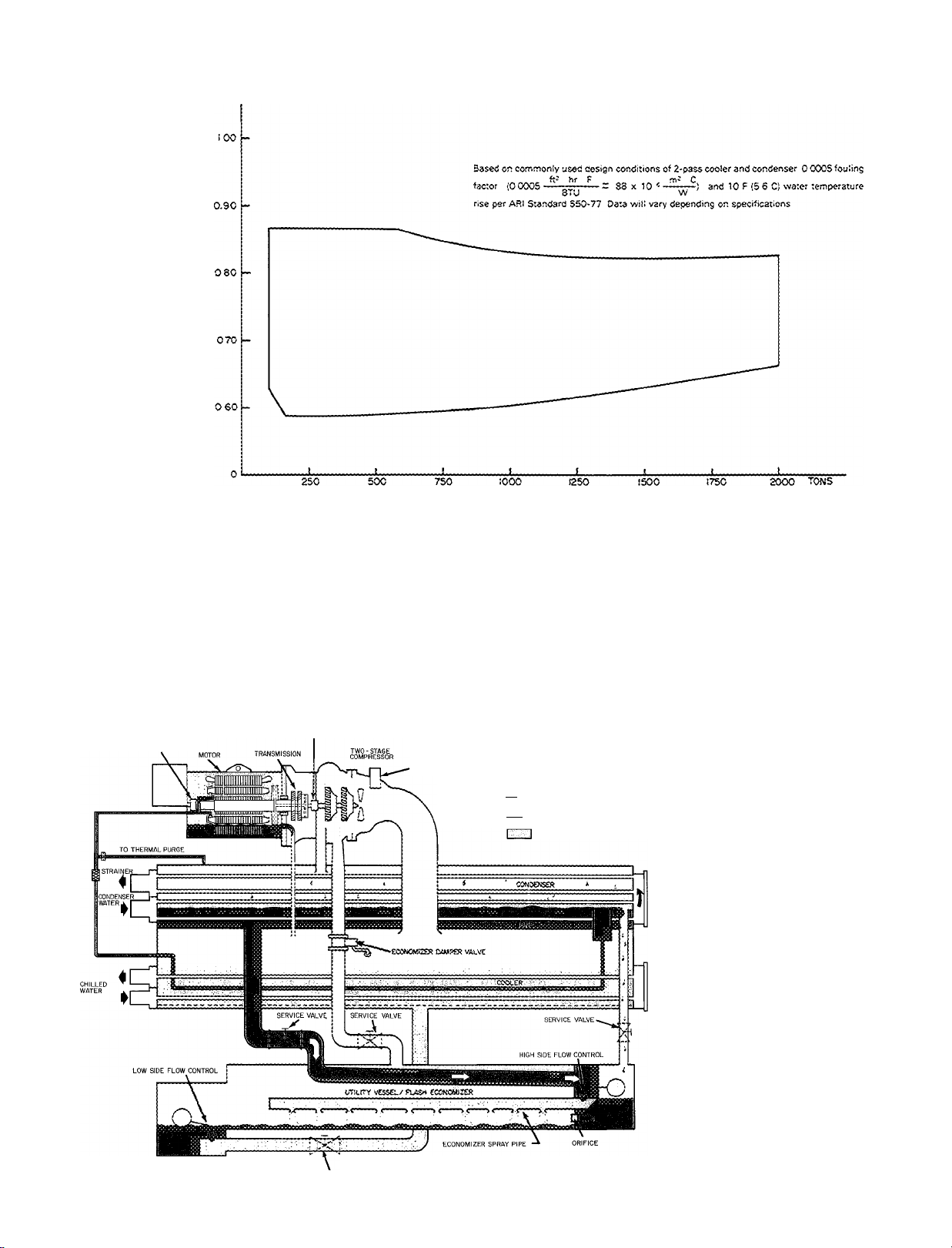
2,000 tons (7034 kW), the Carrier hermetic centrifugals are
capable of performance at levels of .85 KW/Ton (3.0 KW/
kW) to .65 KW/Ton (2.3 KW/kW) and lower, depending on
design conditions. With features such as mix-match capa
bility, high performance heat exchangers, refrigerant
options, multi-pass water boxes as well as tbe 19 Series her
metic compressor designs, a Carrier centrifugal can be opti
mized to meet any job requirement. The “Low Energy Con
sumption Curve” illustrates performance levels possible
within the tonnage capabilities of the 19 Series hermetic line.
You get the most efficient, most reliable, energy-conscious
and completely packaged machine for your particular appli
cation. The hi-lift capabilities (up to 100 F) make the 19
line ideally suited for brine chilling, ice rink applications
and process cooling. In areas with cooling tower restric
tions, you can even specify a hi-lift Carrier centrifugal for
use with closed circuit water condensing systems. The
versatile Carrier centrifugals are also designed for low-lift
requirements of today’s energy-conscious market.
Not only can Carrier Sales Engineers optimize your
refrigeration requirements but they can optimize your total
system as well. Thru various specialized computer pro
grams, for example, a Carrier Sales Engineer can vary your
leaving chilled water temperature a degree or increase your
chilled water temperature differential from 10 to 14 F and
show how the total system is affected with respect to
operating costs. In this complex market of low energy con
sumption as well as low first cost, Carrier can offer you
productive ways to reduce your costs.
Energy-saving, precision
design: extends compressor
motor life, saves on
operating costs, increases
electrical efficiency
• Hermetic design
• Gear-drive compressors
• In-line impeller design
• Refrigerant-cooled motors
• Solid state capacity control
• Thermal purge
• 55 F (13 C) condenser water
• Flash and thermal economizer
• Multi-pass water boxes
• Compressor-motor-heat exchanger mix-match
Engineering excellence
provides lower first costs
and years of trouble-free
service
• Single-unit construction
• Factory-wired oil pump starter
• Permanent shipping bases
• Prepiped motor lubrication package
• Storage tank
• Factory start-up
• Integral chilled water sensor
• Elapsed-time indicator
Carrier’s computer approach to matching the machine
and capacity to a specific application gives you access to
literally thousands of condenser, compressor, cooler,
refrigerant and pass combinations. Initial costs arc lower
because you select only what you need — a smaller
package. Operating costs are reduced because the mix
matching of components allows lower energy consumption
selections. In addition, a Carrier Sales Engineer has the
ability to optimize selections, by varying conditions, thru
the use of the Performance Programs. Should your job
requirements demand performance other than what is
shown in this catalog, contact your Carrier Sales Engineer
(refer to page 50 for the office nearest you). Thru com
puterized selection he will be able to design your “custom
built” hermetic centrifugal.
D
Computer selection saves
time, cuts costs
Full line centrifugal service
centers assure optimal care
of your unit
Convenience options offered
for added energy efficiency,
‘tailor-made’ systems
s
g
U.
(T
UI
a
KWAW KW/TON
f 2SÎ U
( 36;
■: 24;
22;
20) '
s 18'
( 16) [—
"Carrier Offers Low Energy-Consumptiors Selections"
Î^OCO) )20C0)
riOOO) (400C)
CAPACITY
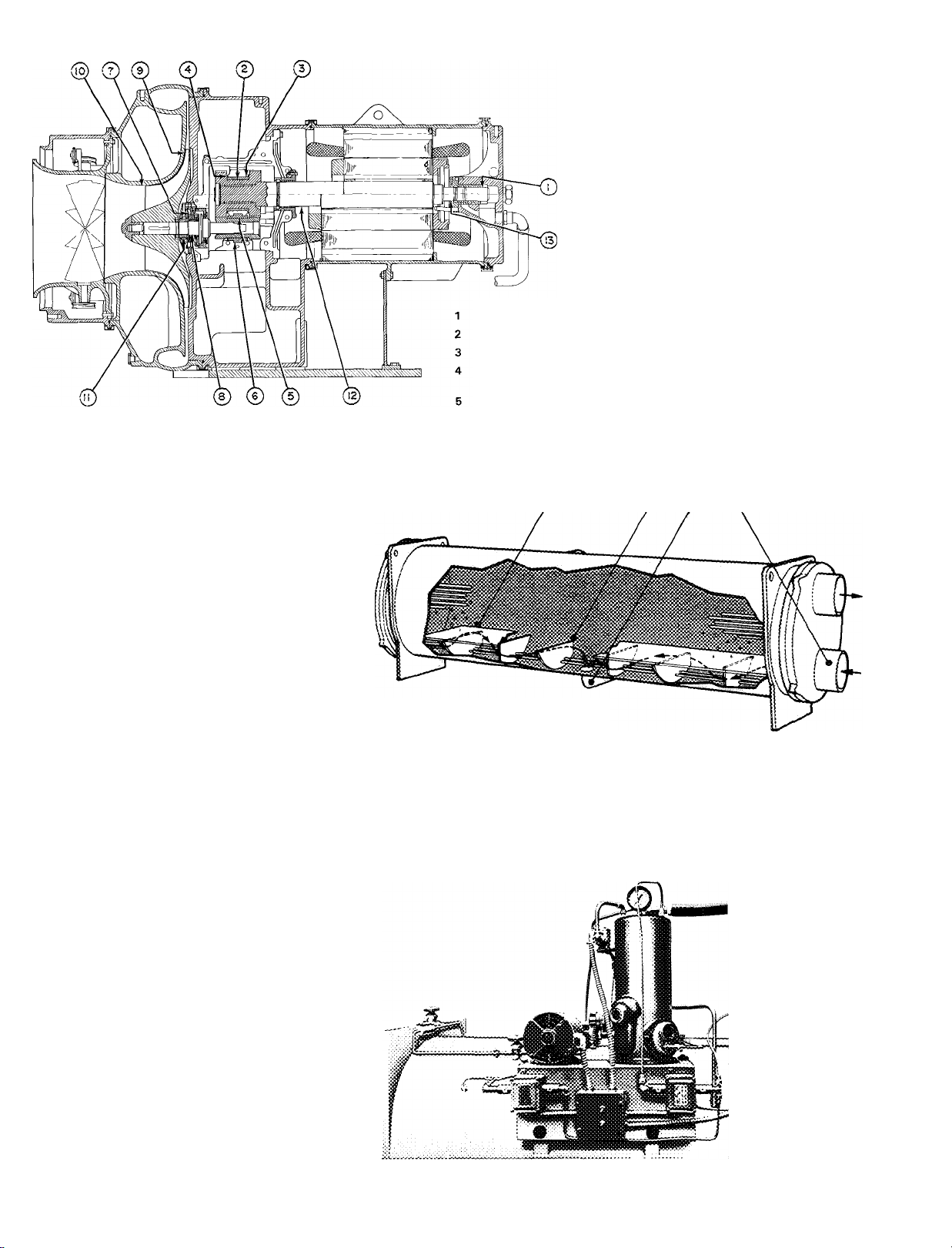
19 Series Centrifugals —
The ideal refrigeration cycle
BEARING AND SEAL
BEARING AND SEAL
VANE MOTOR
i I REFRIGERANT VAPOR
tliiSfel REFRIGERANT LIQUID
SERVICE VALVE
{5COC)
REFRIGERANT LIQUID/VAPOR
•SOCO)
^7000) kW
Carrier centrifugals use refrigerant
(R-11, 114, 12 or 500) in a standard
compression, single- or two-stage
refrigeration cycle. System water in
the cooler is chilled as its heat is
transferred to refrigerant at low tem
perature and pressure. As heat is re
moved from the water, the refrig
erant vaporizes and is drawn into the
compressor at a rate controlled by
the degree of the guide vane opening.
As the compressor raises the vapor
pressure, the saturation temperature
of the refrigerant rises above that of
the condenser water. Refrigerant
vapor is discharged directly into the
condenser, where relatively cool
condenser water removes heat from
the vapor, causing it to condense
again to liquid. The heated water
leaves the system, returning to a
cooling tower or other heat rejection
device. The liquefied refrigerant then
leaves the condenser, draining into
a chamber where a variable metering
device regulates refrigerant flow and
maintains a liquid seal to prevept
vapor from passing into the cooler.
As the refrigerant liquid goes thru
this metering device, part of it vapor
izes because of reduced pressure,
cooling the remaining liquid to the
temperature at which the cycle
began.
Energy-saving, precision design: extends compressor motor life, saves on operating costs, increases electrical efficiency
Hermetic design
Hermetic compressor design keeps
motor free of airborne dirf and mois
ture. It also isolates motor to keep heat
and sound from equipment room.
Eliminates shaft seal with its potential
refrigerant leakage.
■ Gear driven compressors
Gear driven compressors allow more
flexibility in selection than direct drive
because gear ratios can be fitted to
19CB
particular application. Gear driven
compressors also allow optimum im
peller speed, higher head applications
and increased operating efficiency.
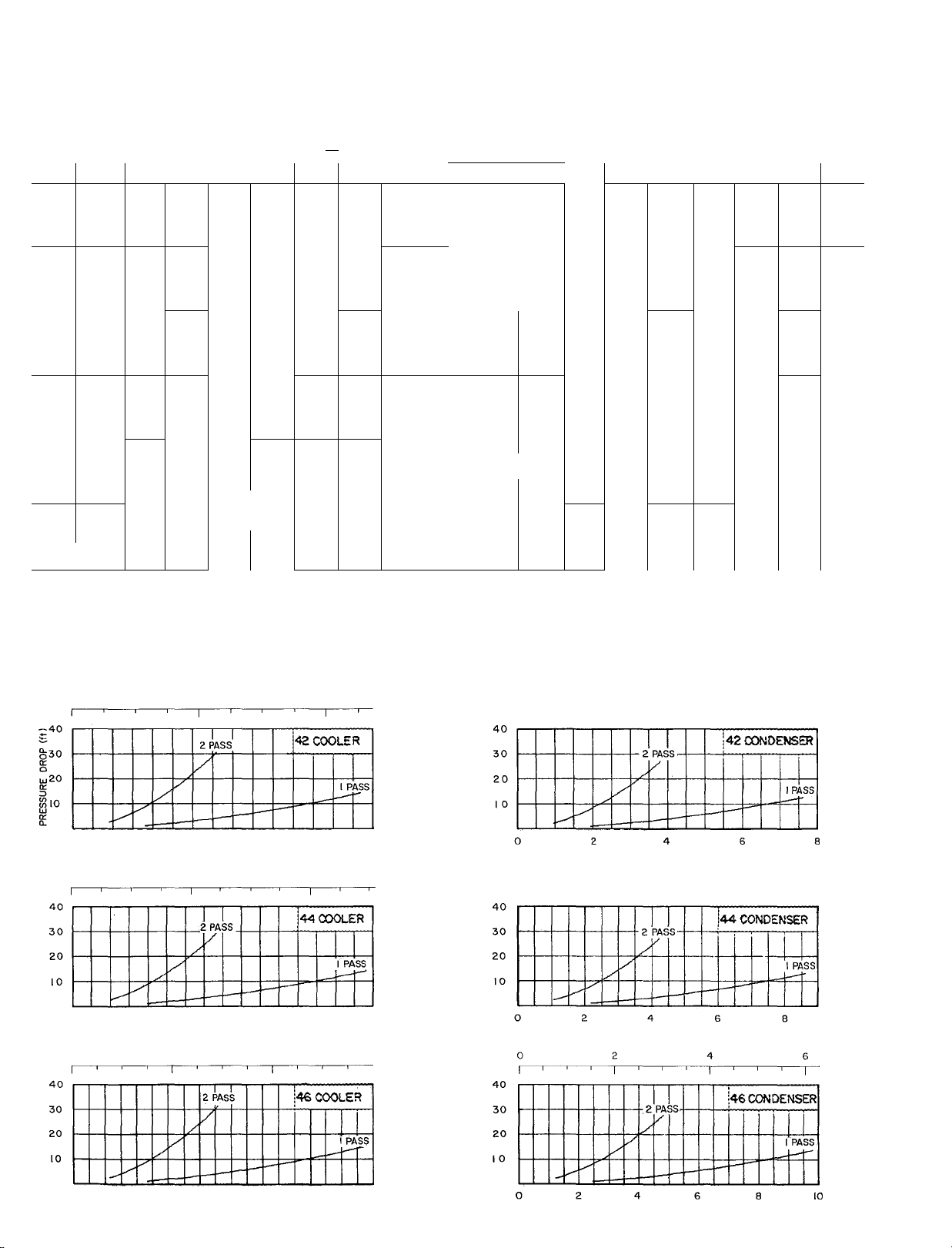
Multi-pass water boxes
The complete 19 Series line offers 1,2,3
and 4 pass water boxes on both the
coolers and condensers. The result is
better heat transfer when needed —
reducing operafing costs. In addition,
all pass arrangements are available at
no extra cost.
Refrigerant-cooled motor
All 19 Series compressors have
refrigerant-cooled motors that operate
at low, even temperatures throughout
the motor windings to insure long motor
life at high electrical efficiency.
19DH
Solid state capacity control
The capacity control module offers
solid state compactness and reliability,
with smooth and precise capacity mod
ulation from 100% to 10% of full load,
without hot gas bypass. It is more
efficient in maintaining leaving water
temperatures than any other type of
control. The convenient, centrally
located control center provides fully
automatic machine operation, com
plete with a full complement of safety
interlocks. Check operating status at a
glance, easily monitor all system oper
ating points. The highly sensitive,
factory-installed thermistor probe, solid
state amplifier, and guide vane actuator
are precisely matched and fully re
sponsive to changes in leaving chilled
water temperature. They help to main
tain your selected design temperature
throughout all operating load condi
tions. The result is efficient, trouble-free
operation with longer life expectancy.
All control connections can be made
quickly to a single terminal strip; and
once the solid state control has been
19EB
19FA
calibrated, control settings may be
changed without additional field
calibration.
55 F (13 C) condenser water
The Carrier metered refrigerant design
allows the 19 Series chillers to operate
efficiently with condenser water tem
perature as low as 55 F (13 C) without
condenser water bypass or mixing
tanks. The 55 F (13 C) condenser water
means reduced head pressures which in
turn means lower horsepower require
ments The end result is lower energy
costs and lower annual operating costs.
In addition, the absence of a condenser
water bypass and mixing tanks add up
to lower first costs and lower installation
costs.
m
LZZZ
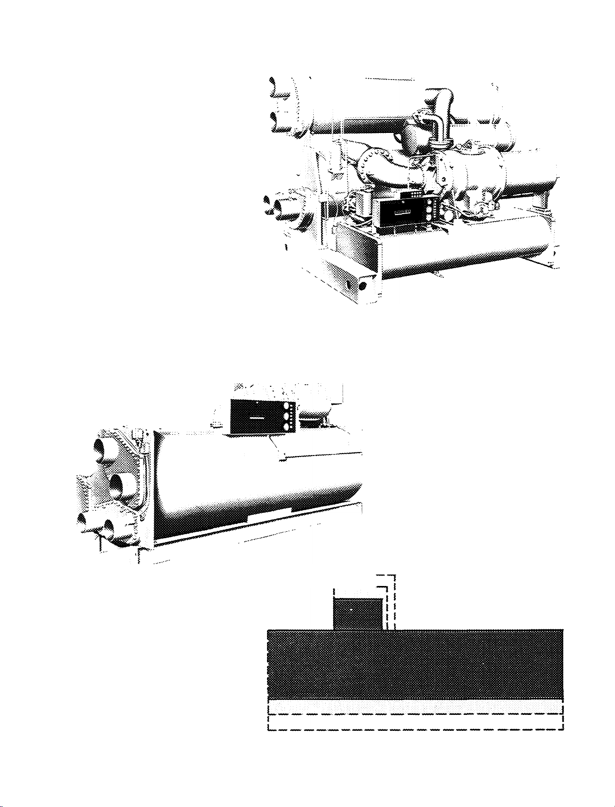
Compressor-motor-
heat exchanger mix-match
Each model within the 19 Series line
has the capability of mix-matching
various heat exchanger sizes with an
array of compressor-motor combina
tions. As illustrated, mix-matching
allows you to mount a small capacity
compressor on a large heat exchanger.
This design concept optimizes specified
conditions, improving full and part load
performance.
19DH
In-line impeller design
In-line impeller design, with diaphragm
between stages, allows for more flexi
bility in compressor component selec
tion, which results in first cost savings
on other machine components. Also
provides higher head capabilities, pre
vents uneven loading and allows for
routine, easy maintenance.
— Motor End Bearing
— Gear Journal Bearing
— Driving Gear Bearing To Housing
— Thrust Clearance on Gear
Bearing (each side)
— Pinion Gear Journal Bearing
— Pinion Gear Bearing To Housing
— Thrust Bearing
LEGEND
8
9
10
11
12
13
— High-Speed Journal Bearing
— Front of Impeller to Volute Wall
— Impeller Eye to ID of Inlet Ring
— Labyrinth Behind Impeller to
Spacer Ring
— Labyrinth Behind Transmission
and Motor Shell
— End-Bell Bearing Labyrinth
Flash and thermal economizer
Two-stage models thru 1,600 ton
(5627 kW) capacity feature a thermal
economizer. The thermal economizer
shown brings warm condensed refriger
ant into contact with the inlet (coldest)
water tubes where water as low as 55 F
(13 C) may be flowing. This low tem
perature water subcools the refrigerant
so when it moves on in the cycle it
has greater cooling potential, thus im
proving cycle efficiency and reducing
power/ton requirements. In addition, all
two-stage models employ a flash econo
mizer, not shown, to further improve
cycle efficiency. The liquefied refrig
erant leaves the condenser thru a
metering device and flows into the flash
economizer where the normal flashing
of part of the refrigerant into vapor is
used to cool the remaining refrigerant.
The flash vapor is diverted directly to
Thermal purge
The thermal purge effectively removes
air, water, and noncondensables from
the refrigerant system, promoting
greater operating efficiency and lower
maintenance costs. It needs no water
connections or air-cooled condenser.
It performs normal system purging
during periods of operation on R-11 and
R-114 machines. In addition, on R-11
machines it doubles as a pump for leak
testing or machine evacuation after
servicing. It also provides recovery of
refrigerant under normal purging
conditions.
19FA THERMAL ECONOMIZER
the compressor’s second stage so that it
does not have to be pumped thru the full
compression cycle. The flash econo
mizer generates savings and signifi
cantly lowers operating costs.
14 *5
14 — Thermal Economizer Partition Plate
15 — Refrigerant Flow Baffle
16 — Refrigerant Liquid Drain Line
17 — Condenser Water Inlet
J6 17
LEGEND
19DH

Engineering excellence provides lower first costs and years of trouble-free service
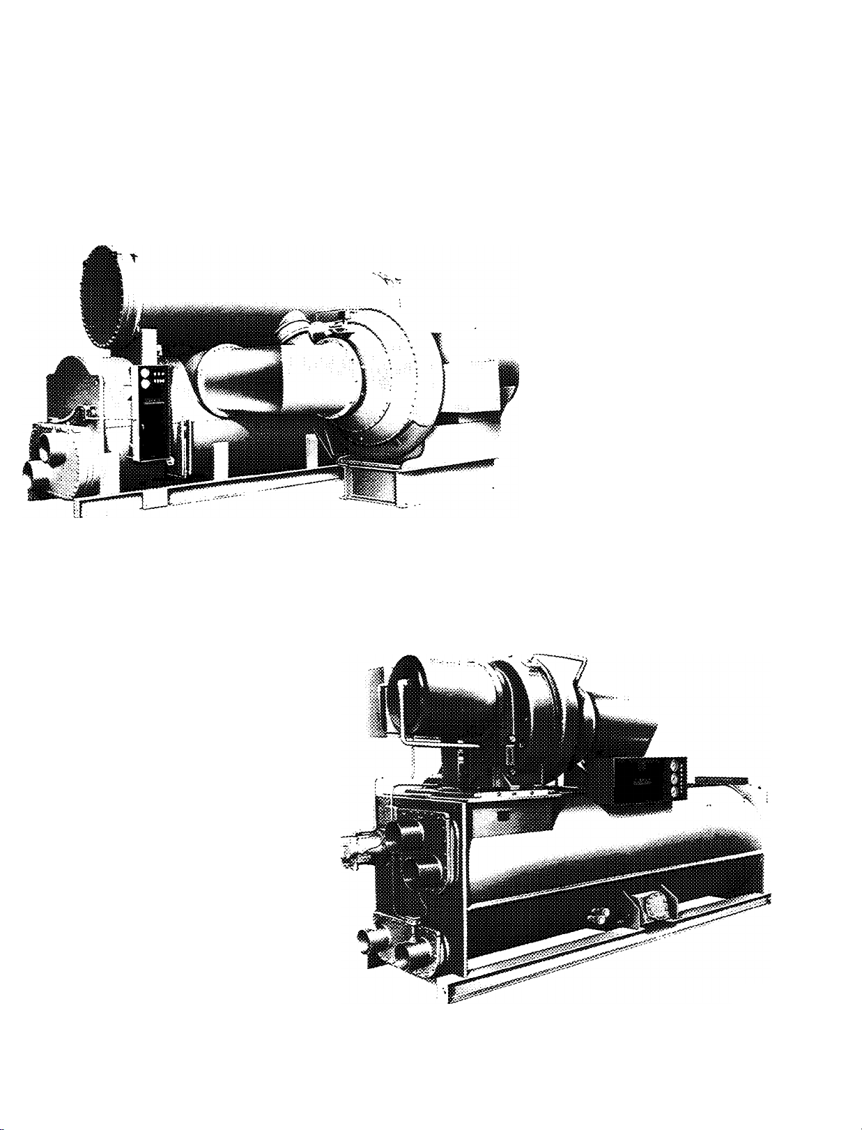
Single unit construction
Carrier centrifugals are the most com
pletely packaged units of their kind.
Chiller is shipped as a single unit com
plete with integral storage tanks where
required. Ready for quick connection
to water and electrical sources at the
job site. (Compressor is field installed
on the 1,600-2,000 ton (5627-7034 kW)
models; the heat exchanger and
economizer are factory assembled.) In
addition. Carrier centrifugals arrive at
the job site with controls mounted and
pre-wired including the chilled water
thermistor. All control connections can
be made to a single terminal strip. Single
unit construction assures minimum in
stallation time, minimum installation
costs.
Factory-wired oil pump starter
Models available for U.L. listing feature
a factory-wired oil pump starter The
starter is factory wired to the machine
with overloads and contactors sized by
Carrier for U.L. compliance. The entire
assembly is factory mounted to save in
stallation time and field labor costs.
Permanent shipping bases
Rigging can be done faster and the need
for costly concrete bases and supports
is eliminated with 19 Series permanent
shipping bases.
Prepiped motor lubrication package
The oil pump, motor, filter, cooler,
pressure controls, and electrical ter
minals are all prepiped and wired to
save on-site labor costs and installation
headaches.
Storage tank
The storage tank is an integral part of
the machine design on all R-12 and
R-500 units. No additional pipings,
fittings or valves are needed. No in
creased floor space is required which
saves you first cost dollars. Servicing or
testing may be easily accomplished
without time-consuming transfer to
separate containers which saves you
service dollars. Models using R-114
offer the storage tank as an option at
minimal cost. They are constructed to
ASME code requirements and include
all necessary connections for refrig
erant transfer system.
Factory start-up
Carrier start-up service for your ma
chine is included in the purchase price.
This assures you of trouble-free, work
ing installation right from the start. It
includes refrigerant transfer, leak test
ing and precision calibrating of the solid
state control settings and safety control
settings.
Integral chilled-water sensor
A chilled-water thermistor probe is fur
nished, installed in the leaving chilled
water nozzle as part of the machine’s
standard control system. A signal from
the sensitive solid-state device to the
central control module automatically
initiates immediate adjustments to com
pressor capacity. This eliminates the
need for accessory pneumatic equip
ment, separate sensing devices, saves
you initial equipment cost, and makes
installation easier, more economical. As
part of the machine’s standard control
system, it does not have to be specified
in another portion of the job, and thus
further reduces first and installation
costs.
Elapsed-time indicator
Every Carrier centrifugal features an
elapsed-time indicator to provide an
immediate and constant record of
machine operating hours. No over- or
underestimating when scheduling
maintenance. Mounted outside of the
control box for easy visibility.
Full line centrifugal service centers assure optimal care of your unit.
When you specify Carrier, you get a complete service
organization unequaled in the industry. Carrier Service
j Operations is a national organization in over 150 key loca
tions throughout the United States and Canada. This is
the one service organization that has grown up with the
air conditioning industry. Today, more and more owners
rely on Carrier Service Operations for an in-depth, practical
approach to energy conservation. This extraordinary full
time commitment to quality maintenance and service
proves Carrier’s interest in continued customer satis
faction. Your centrifugal, in fact your entire HVAC system,
will be in the care of people who are fully versed on the
design, manufacture, installation, start-up and maintenance
of your equipment.
Computer selection means “custom built” machinery — saves design time and lowers cost.
Supplementing the selections in this publication, Carrier
has, for your convenience, developed computer selection
and performance programs for 19 Series hermetic units
that incorporate 800,000 combinations of condenser,
compressor, and cooler components. Computerization of
this data allows you to take full advantage of Carrier’s
tremendous job-matching flexibility.
Only Carrier features the truly optimized selection and
performance programs which are far superior to the limited
combination, manual/ computer compromise selection
systems. With Carrier you have the ultimate flexibility —
you can specify an entering OR a leaving condenser water
temperature; a temperature differential or a water flow rate.
This unique service takes a minimal amount of time and
it’s completely free when you select Carrier.
Remember these advantages you’ll get from using
Carrier’s computer selection service when choosing your
19 Series hermetic centrifugal:
• Fast, accurate equipment selection.
• Comprehensive data, comparing best first cost and best
operating cost selection.
• Accurate matching of components at full and part load.
• Reliable forecasting of owning and operating costs.
• A clear picture of how the chiller functions with the
other components of your system.
• The capability to vary conditions, optimize selections
and define part load conditions with the performance
programs.
• Comparative flow rates applied to various condenser
water temperatures to assist you in selecting the cooling
tower.
• Savings all year long.
Convenience options offered for added energy-efficient, ‘tailor-made’ systems
Pneumatic capacity control
Complete pneumatic control systems
are available, if desired, for the centri
fugals in the 100 to 2000 ton (3527034 kW) sizes.
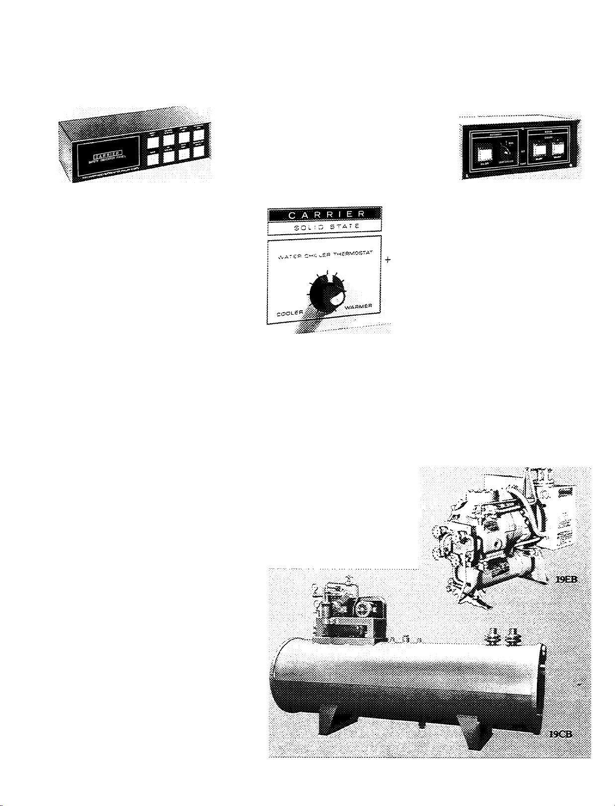
Safety indicator panel
This accessory provides the operator
with an instant trouble-shooting capa
bility. Seven panel lights monitor high
motor or bearing temperature, low
refrigerant temperature, high con
denser pressure, starter (overloads and
protective devices), low water flow
(chilled or condenser), low oil pressure,
low chilled water temperature. When
safety is tripped, the light goes on. Panel
does not affect the integrity of the
central control system, is easily con
nected to the machine without disturb
ing factory wiring. In addition, a remote
sound or light alarm can be easily field
installed to alert you, should a safety
light be tripped on the indicator panel.
Only a simple two-wire hook-up is
required.
Selective insulation
The 19 Series machines are adequately
insulated at the factory to meet most
application demands. However, addi
tional insulation packages are available
for specific machine applications.
Isolation assembly
A combination of soleplates, jacking
screws, leveling pads and neoprene
pads are available in isolation packages.
Specify this option for installations
requiring special mounting. Isolation
pads are shipped at no charge.
Remote control set point
Select or alter machine chilled water
temperature from a remote location by
specifying this optional solid state
control.
Pumpout unit
Factory mounted, complete with
starter, controls and all necessary inter
connecting refrigerant piping. Permits
easy transfer of refrigerant between
machine and storage tank. Speeds
servicing and minimizes downtime. On
multiple machine applications, a single
pumpout unit saves first costs. Not
required for R-ll units.
Lead-lag control
Desirable when two or more machines
are installed in series or parallel. Cen
tralized control features the following
capabilities;
• parallel operation
• series operation with split or common
point control
• two or more chiller operations
• uneven sized chillers working
together
• independent control of chillers both
manually and automatically
• automatic lead-lag operation
• reassignment of lead-lag hierarchy
• automatic standby
Panel lights indicate system operating
mode.
Hot gas bypass
When a machine is expected to run at
light load and elevated condensing tem
peratures or at minimum load for ex
tended periods of time, a hot gas bypass
is recommended. The hot gas bypass is
factory mounted and wired, manual or
automatic. It virtually eliminates com
pressor surging at extreme part-load
conditions and smooths out the ma
chine’s full operating cycle, whatever
the load fluctuation.
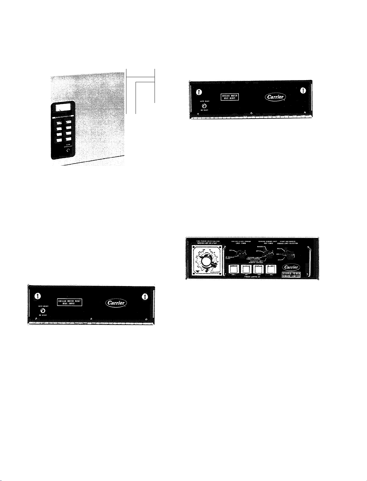
Additional energy-saving options
Chilled water self-reset control
This device permits the leaving chilled water tempera
ture to rise as the load on the machine decreases.
The higher the leaving chilled water temperatures, the
less work the compressor is forced to do.
The power monitor control
An electronic, energy-saving device which continuously
monitors building electric demand and sheds preselected
loads in stages during peak power usage periods. The
power monitor control reduces power consumption and
minimizes power demand charges.
Chilled water reset-dual input
A device that causes the leaving chilled water tempera
ture control set point to change in proportion to a change
in a remote temperature such as return chilled water or
outdoor air temperature.
Adjustable stepped-rcset control
A device that permits leaving chilled water tempera
ture to rise in predetermined adjustable steps. Operator
is in control of demand limit so amount of reset is not
dependent on machine load but on the amount of change
of resistance in the probe circuit.
Stepped power demand limiter
This option makes it possible to limit power demand in
four ways:
1. At start-up each chiller can be held to a preselected
maximum current draw for any time period of up to
one hour.
2. During normal operation, chiller load can be auto
matically reduced in up to 3 stages in response to
increased total building power consumption.
Chiller demand can semi-automatically be lowered in
3.
a single stage in response to increased total building
power consumption.
4.
Chiller demand can also be lowered manually.
Stepped power demand limiter minimizes the likeli
hood of getting demand charges. Also has timer which
increases flexibility of operator. Operator can change
demand limit without being at controls and can also
adjust demand limit manually.
#
10
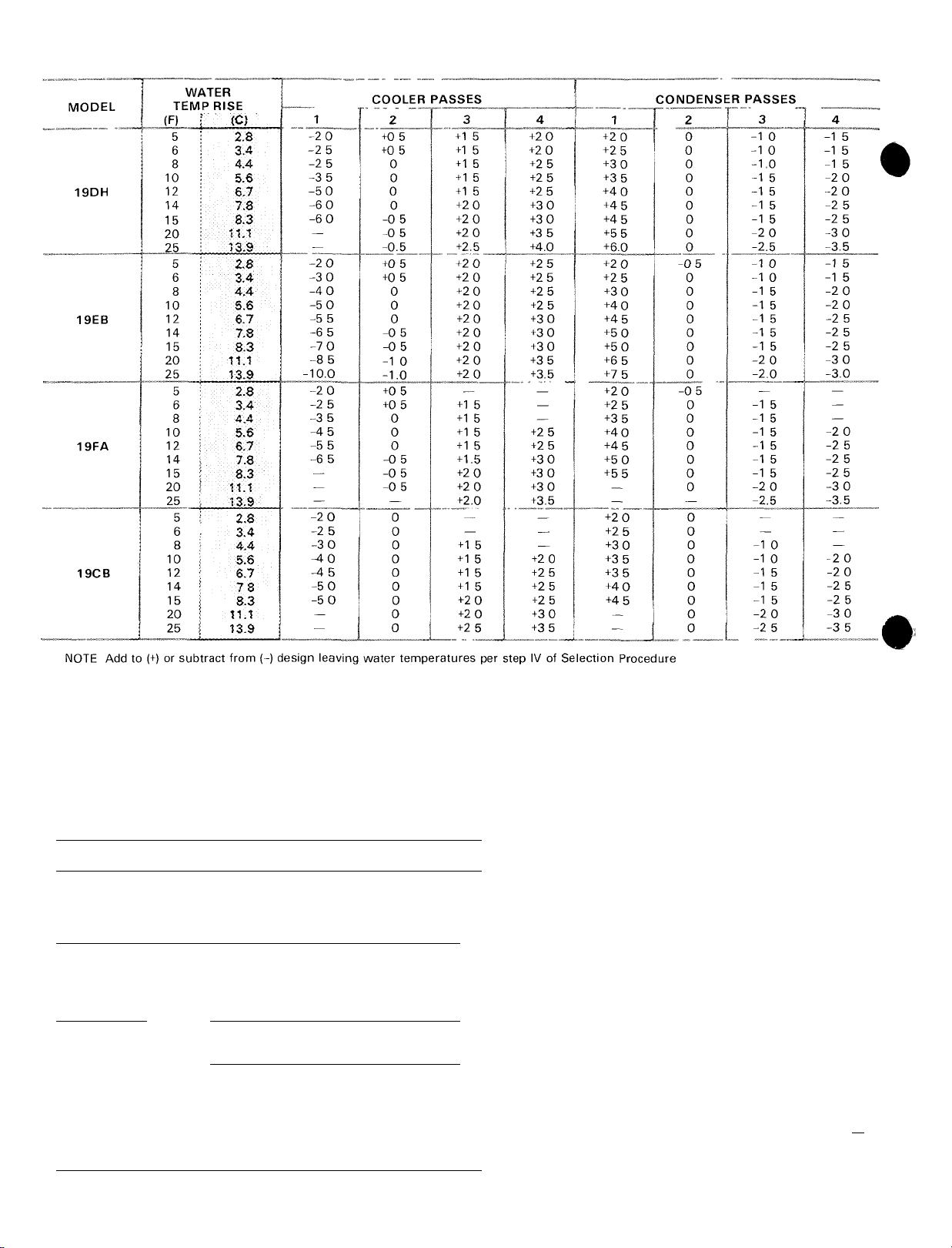
PASS-RISE TEMPERATURE ADJUSTMENT (F/C*)
*To convert the temperature adjustment factor to °C, divide by 1 8
Metric
tech
Area
cm2 100
cm3
m3 1 0
m2
Length
mm 1.0
mm 0 03937
mm 0 003281
m 1 0
m
Mass
kg
kg
Power
kcal/h 1 163
kcal/h 3 968 Btu/h 0 2931
HP metric
HP metric
Mcal/h 1 163
Mcal/h
X =
0 1550
10 76
3 281 ft
2 205
0 9863
0 3307
English
unit X =
ip2
«2
in
ft
lb
HP(550
Ton refr 3 517
645 2
0 09290
25 4
304 8
0 3048
1 0
0 4536
0 7355
0 7457
CONVERSION TABLE
SI unit
mm2
mm2
m2
m2
mm
mm
mm
m
m
kg
kg
w
w
kW
kW
kW
kW
Metric
tech
Pressure
mm w g 4°C
mm w g, 4°C
mm Hg 0°C
mm Hg 0°C
kg/cm^
kg/cm^
Temperature”
Interval
°C
y
Velocity
m/s
m/s
__
m/s _
Volume/Time
m®/h
m^/h
m^/h
L/h
__
L/h
Metric
tech
Temperature
“C
°C
0 03937
0 03937
^14 22
1 8
3.281
196.9
0 5886
4 403
4 403x10-3
Conversion
factor =
(»Cx18)+32 °F
English
unit
inHjO 39 2 F
in Hg 32“ F
psi
°F
ft/s
ft/min
fH/min
U S gal/min
U S gal/min
nEhglish
Un»
0 009806
0 2491
0 1333
3.386
98.07
6 895
1 0
0^5556
1 0
0 3048
0.00508
0 2778
0 4719
0 06309
2 778x10-“'
0 06309 _
Conversion
factor =
“C+273 15
(°F-32)-r1.8
SI unit
kPa
kPa
kPa
kPa
kPa
kPa
K
°C
m/s
m/s
m/s
Us
L7s
tVs
Us
Us
____
SI unit
K
°c
_
#
12
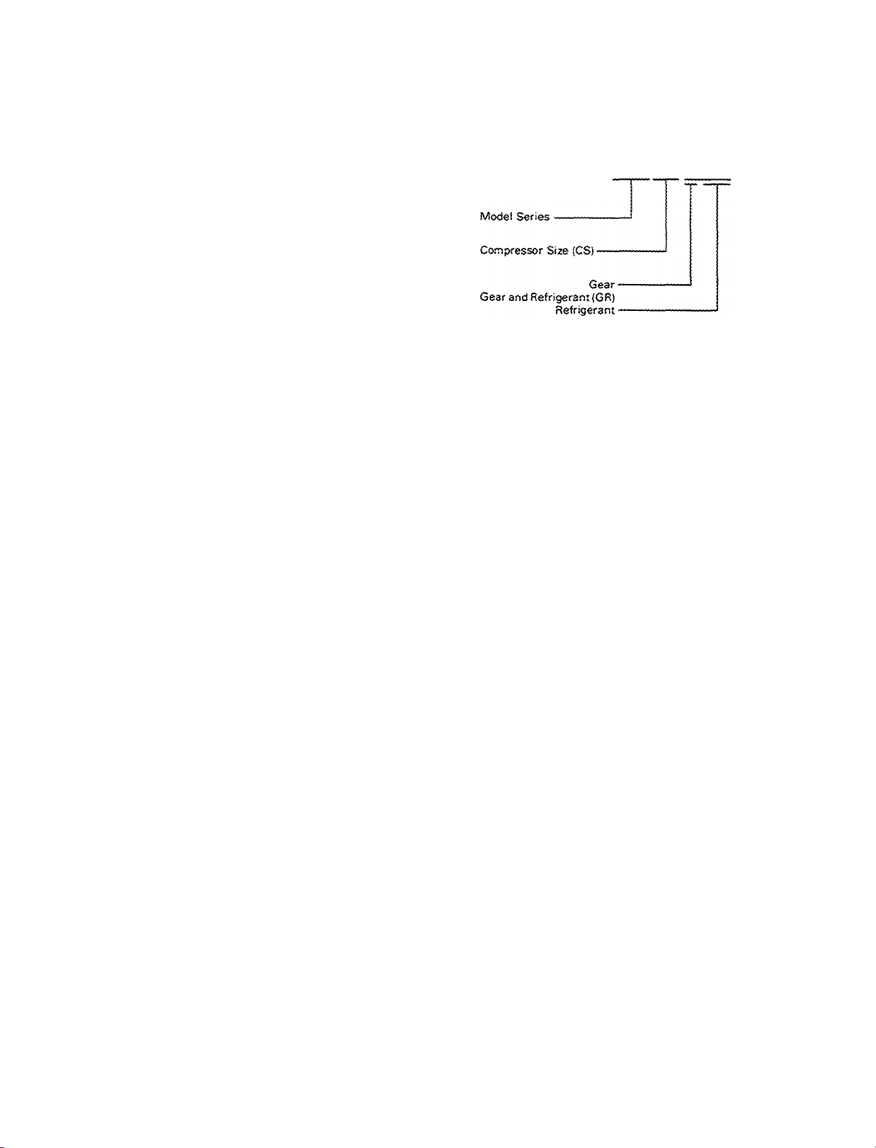
Using the 19DH,EB,CB model numbers
When ordering 19DH, 19EB or 19CB chillers, use the
ordering code described below. Chiller nozzle arrange
ment and compressor voltage must be listed separately.
Using the 19FA model number
When ordering 19FA chillers, use the ordering system
described below.
(19C8) Condenser-------------------------------------------------Heat Exchanger (HE) (UN){19CB) Cooler------------------
19EB8165DK
Model (19DH, 13EB, 19CS)-
Heat Exchanger or Unisheil (UN) •
Compressor (CS)
Motor---------------------------------------
List chiller model in first 4 code number positions
Obtain Unishell or heat exchanger size from step V of the Selec
tion Procedure and enter in positions 5 & 6
Obtain compressor size from step V of the Selection Procedure
and enter in positions 7 & 8
Obtain motor size from step VII of the Selection Procedure and
enter in positions 9 & 10
-----------------------
13FA563-B-500-2425-L-EC
Cooler -
Heat Exchangers (HE)
Condenser-
Base Size (S, small or L, large)
Motor Size (MS)-------------------------------------------------------------
1 List chiller model in first 4 code number positions
2 Obtain compressor size from step V of the Selection Procedure
and enter in positions 5, 6 and 7
3 Also from step V of the Selection Procedure, obtain gear size
and refrigerant used Enter gear size in position 8, next enter
refrigerant in 9-11 (May only need to use 9 & 10 )
4 Obtain heat exchanger size from step V of the Selection Pro
cedure and enter the cooler size in positions 12 & 13 and the
condenser size in positions 14 & 1 5
5 Base size is indicated in position 16
6 Obtain motor size from step VII of the Selection Procedure and
enter in positions 17 & 18
Part-load energy requirements
At part load, chiller energy requirements are aifected by
many variables, such as degree of load, chilled water flow,
condenser water flow, entering condenser water tempera
ture, leaving chilled water temperature, and the percentage
of compressor loading at design conditions.
Because of these many variables, a typical part-load
curve (% Standard Rating Tons versus % Standard
Rating Kw Input) may have appreciable inaccuracies
when applied to a specific chiller and set of conditions.
Carrier, therefore, does not recommend the use of
such curves in making operating cost studies.
Instead, thru computer analysis. Carrier will provide
you with accurate and detailed information on the energy
requirements for your selected chiller at the expected
jobsite conditions.
Energy savings can be significant if the chiller can be
operated with a relatively low entering condenser water
temperature. And, since conditions of design load and
design wet-bulb temperature can occur rather infrequently,
the opportunity for such savings exists during most of the
operating season. Each chiller is capable of operating
efficiently with entering condenser water temperatures
down to 55 F (13 C). This capability assures you of both
energy conservation and excellent part-load performance,
because “custom-made chillers” give the best part-load
performance.
13
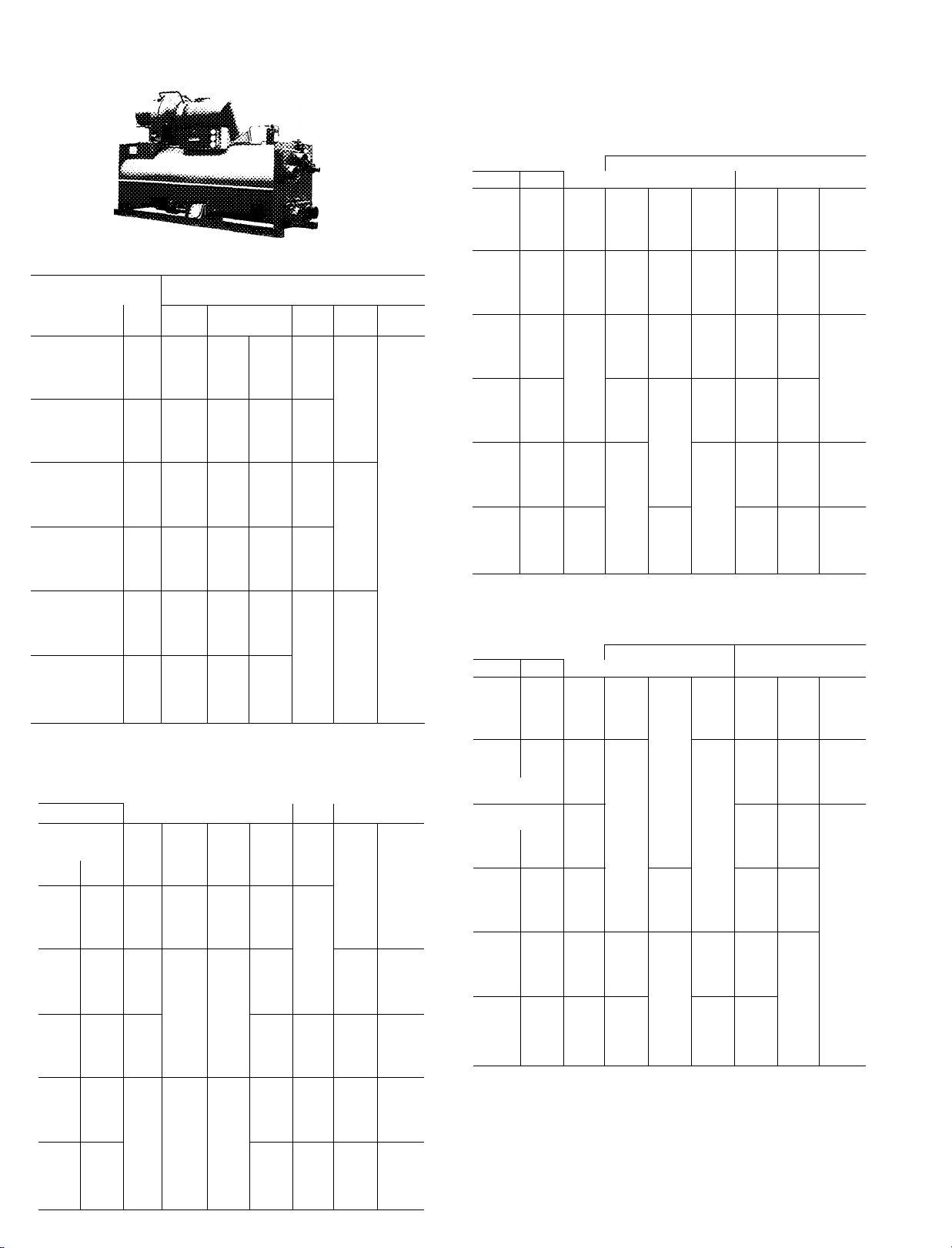
19DH Selection data
19DH*
100-450 TONS
(352-1583 kW)
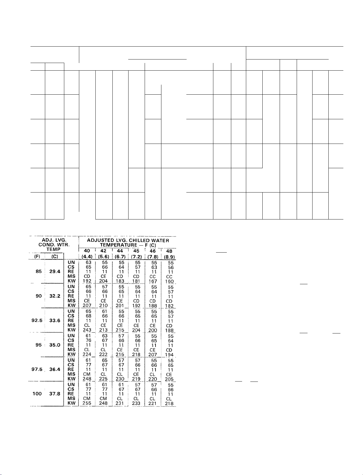
100 Ton Selections (352 kW)
ADJ. LVG.
COND. WTR.
TEMP.
(F) ! (C)
1
;
85 ! 29.4
90 ; 32.2
92.5 ; 33.6
95 ; 35.0
•
97.5 ! 36.4
:
100 ! 37,8
UN 42 42 42 42
CS 13 13
RE
MS AA
KW 78 76
UN 42 42
CS
RE
MS
KW 86
UN
CS 15
RE 11
MS AA
KW 92 86 83 80
UN
CS
RE
MS AB
KW 97 92
UN 42 42
CS
RE
MS AC AB
KW 107 97
UN 42 42
CS
RE
MS
KW
125 Ton Selections (440 kW)
ADJ. LVG.
CONO. WTR.
TEMP.
(C) (4.4)
(F)
85
29.4
90
32.2
92.5
97.5 36.4 RE
95
100
33.6
35.0
37.8
UN 42
CS 27 20 13 19 12 12
RE 11 11 11 11 11 1 1
MS
KW
UN 42 42 42 42 42 42
CS
RE 11 11
MS AC AC
KW 114 107
UN 42
CS 29 22
RE 11 11
MS AD AC
KW 117 114 106 102 102
UN
CS 30 23
RE 11 11
MS AD AD AC AC
KW 125 121
UN
CS
MS AE AD
KW 136 125
UN
CS 31 24 23 23
RE 11 11
MS AE AE AD AD AD AC
KW 139
ADJUSTED LVG CHILLED WATER
TEMPERATURE — F (C)
42 ! 44 i
40
(4.4)
(5.6) ! (6.7)
11 11
AA AA AA
14 14 13 13
11 11 11 11 11
AA AA AA AA
AC
111
40
AB AB AB AA AA AA
101
r 42
83
42 42 42 42 42
14 14
11 11 11 11
AA AA
42 42 42 42 42
16 15 15 14 14
11 11 11 11 11
AA AA AA AA
17 16 15 15 15
11
11
17 17
11 11 11 11 11
AC
107
ADJUSTED LVG. CHILLED WATER
TEMPERATURE — F (C)
(6.7)
(5.6)
42
97 96
29 21 20 13
42 1
44
42
24 30 22 22
11
11
44 44
135
45
(7.2)
13 12
11 11
74
42
78 77 76
89
42 42
11 11 11
AA AA
92
42 42
16
AB AB AB
97 96
44 T 45
(7.2)
42
11
AB AB
100
42
21
1 1
AC AB
42
21
11 11
110
42 42
11 11
AD
117
42
11
125 122 116 111
46
(7.8)
* *
68
42
42
13
AA
13 13
AA AA
79
84
85
42
AA
91 89
42
16 16
95
46 48
(7.8)
42 42
88 87
13
11 11 11
AB AB
100 98 95
42 42 42
20
13
11 11 11
AB
42 42
21 14 13
11
AC
108 108 101
AC AC AC
115 114 107
42
15
11
42 42 42
22
11 11 11
48
(8.9)
*
*
*
*
*
(8.9)
42
84
13
13
AB
98
42
11
AB
42
14
11
14
150 Ton Selections (528 kW)
ADJ. LVG.
COND. WTR.
TEMP.
85
90
95
100
(C)
29.4
32.2
33.6
35.0
37.8
UN 46
CS 35 27 27 27 26 19
RE 11
MS
KW
UN 46
CS 37
RE 11 11 11 11 11
MS AE AD
KW 141
UN 50 46 46 46 46 ^ 46
CS 37 36
RE 11 11 11 11 11 11
MS AE AE
KW 142 134 127 121 119
UN
CS 37 37 35 28 28 20
RE 11 11 11 11 11 11
MS AE AE AE AE AD AD
KW 141 144
UN 50 53 46 46 46 46
CS 47 36 36 29
MS CB AE AE AE AE AD
KW 156
UN 50 50 51 50 46
CS 47 47 36 29 29
RE 11 11 11 11 11
MS CC CB AE AE AE
KW
(F)
92.5
97.5 36.4 RE 11 11 11 11
ADJUSTED LVG. CHILLED WATER
TEMPERATURE — F (C)
40 42 44
(4.4)
(5.6)
46 46
11 11
AD
AD AC AC AC AB
124
116 112 113 105 102
46 46
35
127 119
53 46 46
136 139
156
160
175 Ton Selections (615 kW)
ADJ. LVG.
COND. WTR.
(F)
85 29.4
90 32.2
92.5 33.6
95
97.5
100
LEGEND
CS — Compressor
GR — Gear-Refrigerant
HE — Heat Exchanger
KW — Power Input
MS — Motor Size
RE — Refrigerant
UN — Unishell
14
TEMP.
(C)
35.0
36.4
37.8
UN
CS 43 43 34
RE
MS
KW
UN
CS 51 44 35 35 35 34
RE 11
MS
KW 147 144 141 142
UN
CS 52 44
RE
MS CC CB
KW
UN
CS
RE
MS CC CC CB CB AE AE
KW
UN
CS 54
RE 11 11
MS CD
KW
UN
CS
RE
MS CD CD
KW
ADJUSTED LVG CHILLED WATER
TEMPERATURE — F (C)
40 1 42
(4.4)
(5.6)
50 50 51 50 50 50
11 11 11 11 11 11
AE
AE AE AE AE AD
133
138
50 50
11 11 11 11 11
CB
CB AE
50 50
11 11
156
150
50 50 50
53 52 44
11 11 11
166 156
50 50 50 50 50
46 45 45 44 34
CC CC
183 169 157 155
50 50
54
47 46 45
11 11 11 11
189 186
(6.7)
(6.7) (7.2)
45
(7.2)
44 44
11
46
27 27 20
AD
AD AD
117 115
27 27
28
AD
AD AD AD
46
130 128 127 119
136
138
139
44
45
34
130
130
143
148
168
51 50
53
AE
50
44
11
AE AE AE
CB
143
11
146 144
11
11
CB
50
CC CC
160
53 51
35
11
50
44
50
r 48
46
(7,8) (8.9)
11 11
46 46
46
28
11 11
130 122
138
46 48
(8.9)
(7.8)
34 26
128 116
AE AE
141 131
35 34
11
142
53 51
35 34
11 11
11 11
CB AE
148 140
50 I 50
45 45
11 11
CC CB
157 153
44
19
11
AC
105
20
115
46
27
46
28
11
AE
129
11
136
138
#
50
50
53
200 Ton Selections (703 kW)
ADJ. LVG
COND. WTR.
TEMP.
(C> (4.4)
(F)
85
29.4
90
32.2
92.5 33.6
95
35.0
97.5 36.4
100
37.8
UN 51
CS
RE 11 11
MS
KW
UN
CS
RE
MS CC
KW 166
UN
CS 59
RE
MS CD
KW 176
UN
CS 60 52
RE
MS CD
KW
UN
CS 61
RE
MS
KW
UN
CS
RE 11 11
MS
KW
A
DJUSTED LVG.
TEMPERAT
" 42 “I 44
¡5.6) ; (6.7)
51 51
57
50
CB
CB AE
156 151
53 51 51 51
58 51
11 11
CC
164 155
53 51
58 51 50
11 11
CC CC
170 164 156
53
53 51"’ 51
11
11 11 11
CD CC
188 175 171
53 53
59 51 51
11 11 11
CE CD
207 181 171
53 53
61
60
CE CD
215 193
CHILLED WATER
JRE — F (C)
49 49 42
11
140 136
50
11
CB CB
51 51
11 11
51 51
53 53
CC
53 53
52
11
CD
181 177 171
45
(7.2)
51
11 11
AE
50
11
152
CC
CC
167 164
11
CC CC CC
168 169
52
11 11
CD CC
46
(7.8)
(8.9)
51
AE
136
51
43 42
11
CB AE
152
141
51 51
43
11 11
CC CB
156 151
51
51
11
CC CC
156
51 51
51 44
11 11
166
53 51
51 51
CC
169
275 Ton Selections (%7 kW)
ADJ. LVG.
COND. WTR.
48
51
42 CS
11
AE MS CE
51 UN
11 90
43
51
43
11 95
1 1 100
TEMP.
(F) (C)
85
29.4
32.2
92.5
33.6
35.0
97.5 36.4
37.8
40
(4.4)
UN 61
RE 11
KW
203 197
61 61 65
CS 81
RE
11
CL
MS
KW
219
UN 61
CS 82
RE 11
MS CL CL
KW
233 222
UN 61
CS
RE
11 11
MS CM CL
KW
248 236 221
UN 61
CS
RE 11
MS CN
KW 276
UN
61 61
CS 84
RE
11 11 11
MS CN CN
KW 281
ADJUSTED LVG. CHILLED WA1
TEMPERATURE — F (C)
42
44
(5.6)
(6.7)45(7.2)
61
73
CD CD
CE
210
63 61
73 64 64
11 11
73
11
61
74
11
CD
195
196 178 171
65
11
CE
CL
210
223 202
65
66
11 11
CL CL
11
61
66 64
11 11 11
63 61 61
66 65 64
224 224
83
^ 61 61
75 74
CL CE
11 11
65 61 61
65 67 64
219 241
77 76
11 11
CM CL
251 236
77 76
276 250
6Ì 61
CM CM
61
75 75
11 11 11
CL CL
232 234
61 61
11
246
76
■ ER
48
46
(7.8)
(8.9)
61 61
63
11 11
CD CD
61 61
CE CD
184
11 11
CE
CE
217 201
11 11
CL
CE
208
63 61
66
CL
222
65 61
66 66
11 11
CL
CL
236 236
56
63
65
250 Ton Selections (879 kW)
300 Ton Selections (1055 kW)
ADJ. LVG.
CONO WTR
TEMP.
(F) (C)
85 29.4
90 32.2
92 5 33.6
95 35.0
97 5 36.4
100 37.8
UN
CS
RE
MS
KW.
un'
CS
RE
MS
KW
UN
CS
RE
MS
KW
UIM^
CS
RE
MS
K^
UN
CS
RE
MS
KW
UN
CS
RE
MS
KW
ADJUSTED LVG. CHILLED WATER
40
(4.4Ì
61
80
11
CL
223
61
82
11
CM
252
61
83
11
CN
267
61
90
11
CN
274
éf
84
11
CP
306
63
84
11
CP
307
TEMPERATURE — F JC)
44 "T
42
¡5.6)
61
73
11
CL
219
61
81
11
CL
236
’ 61 ’
81
11
CM
243
61
82
11
CM
259^
61
83
11
CN
274
61
84
11
CP
303
211
(6.7) :
61
73
11
CE
61
73
11
CL
225
6l’
74
11
CL
240
éi"
75
11
CM
255
61
82
11
CM
258
61
83
11
CN
273
45
¡7.2)
61
72
11
CD
197
61
73
11
CL
2M
"'61
73
11
CL
228
61 ’
74
11
CM
242
61
75
11
CM
259
61
76
11
CN
274
46
(7.8)
61
72
11
CD
.1?3
61
73
11
CE
.217„
6Ì"
73
11
CL
224
6l"
74
11
CL
238
61
74
11
CM
246
61
75
11
CM
262
48
63
63
11
CD
189
65
64
11
CE
212
65
64
11
CE
218
73
11
CL
223
61
74
11
CL
238
61
75
11
CM
252
*For additional tonnage and performance selections contact your nearest Carrier Sales Office (see page 50)
15
19DH Selection data (cont)
350 Ton Selections (1231 kW) 400 Ton Selections (1407 kW)
ADJ. LVG.
CONO. WTR.
TEMP.
(fT
92.5
97 5 36.4
100
(C) (4.4)
85
29.4
90
32.2
33.6
95
35.0
37.8
UIM
CS 95
RE 11
MS
KW 271
UN 63
CS
RE
MS CP
KW
UN 65
CS 97
RE
MS CP
KW 311
UN 65
CS
RE 11
MS CQ
KW 344
UN 65
CS 98
RE 11
MS CQ
KW 352
UN
CS 98
RE
MS
KW
LEGEND
CS — Compressor
GR - Gear-Refrigerant
HE — Heat Exchanger
ADJUSTED LVG. CHILLED WATER
_ JTEMPERATURE — F (C)
42 44
40
(5.6) (6.7)
63
63
87
CN CM CM CL CL
11 11
255 247
gg
95
97
11
11
CN CM
279 263 259
309
CQ
358
63
96
11 11
11
CP CN
297
63
97 89
98
11 11
CP
317
65 63
97 90
11 11
CP CP
319 316
65
72
91
11 11 11 11 11 11
CQ CP
352 318 321 305
KW — Power Input
MS — Motor Size
RE — Refrigerant
UN — Unishell
45 46
(7.2) (7.8)
63 63 63
80 86
229 225
63 63 63
87
11 11 11 11 90
CM
63 63
88 87 80 80
CN
278 265
63 63 63 63
CP CN CN CM
296 282 276 261
CP
300
65 63 63 63
90 90
CP
79 72 CS
11
11
80
80
CM CM
254
63
11
11
CM
264
88 81 80
11
11
63
63
82
89
11
11
CN CN
294
89
CP CN
ADJ. LVG.
COND. WTR.
48
(8.9)
63 UN
11 85 23.4 RE
CL
220
63
73 CS
249 KW 335 339 309 294
63
11
CM
252
11
63
81
11
276 KW
82 CS 97 97 97 89
295 KW
TEMP.
95
(C>
32.2
35.0
36.4 RE
37.8
(F)
92.5 33.6
97.5
100
MS
KW
UN
RE 11 11
MS
UN
CS
RE
MS
KW
UN
CS 97 97 96 95 87
RE
MS CQ CQ
KW 348 350 333 318 297
UN 77
CS
MS
UN
RE
MS CQ CQ CQ
ADJUSTED LVG. CHILLED WATER
TEMPERATURE — F (C)
40 142 44 45
(4.4)
(5.6) (6.7)
76 71
95 95 94 87 86
11
CP CP CN CN CM CM
298
CQ CQ CP CN CN CN
CQ CQ CQ CP CP CN
338 344
11
301
77 72
97 97
78 73 71
97
97 96 95
1 1
11 11 11 11 11
76
*
11 11 11 11
97
*
11 11 11 11 11
CQ
353
*
*
(7.2)
71
71
11
11
279 275 256
326 313 299 286
CQ
71
71
94
95
11
11
71
71
71
CQ
71
73
97 96
97
CQ
356
352
76 73 72
11 11 11 11
357
358
46 48
(7.8)
(8.9)
71
11 11
71
87 80
11 11
281
288
71
94
71
CP
71
CQ
338 317
356
71
79
247
71
71
87
71
11
CP
71
88
CP
71
CQ
334
UNISHELL COOLER
FLOW RATE L/s
.2
2 4
FLOW RATE. GPM (lOO's)
100;
50
- 100
- 50
iOO
UNISHELL CONDENSER
- 100
50
.2
- 100
-* 0
100
50
16
50
-* 0
Loading...