

Page 1
OOPPEERRAATTIIOONN AANNDD IINNSSTTRRUUCCTTIIOONN MMAANNUUAALL
GGRRAANNIITTAA MMAACCHHIINNEE
MMooddeellss::
RReeff..:: SSLL99000044991122332
GGHHZZ —— 222288 SSFF FFRREEEEZZIINNGG PPOOIINNTT
RReeff..:: SSLL99000044991122333
GGHHZZ —— 334422 FFFF FFRREEEEZZIINNGG PPOOIINNTT
111155 VV.. —— 6600 HHzz..
2
3
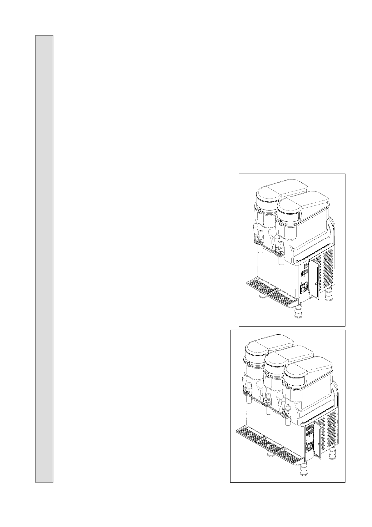
GHZ-228 SF FREEZING POINT
GHZ-342 FF FREEZING POINT
Page 2

Copyright© Freezing Point , 2004
Page 3

Granita Machine Operation and Instruction Manual
INDEX
Index _____________________________________________________________ 3
Unpacking _________________________________________________________ 4
Important __________________________________________________________ 4
Positioning the machine _____________________________________________ 4
Important __________________________________________________________ 4
Familiarizing yourself with the Controls_________________________________ 5
Cleaning and Sanitizing instructions ___________________________________ 6
1 Unlock handle l oc k i n g s y s t e m _______________________________ 6
2 Cleaning the bowl_______________________________________________ 6
3 Cleaning the bowl gasket_________________________________________ 7
4 Cleaning the spiral ______________________________________________ 7
5 Cleaning the drip trays___________________________________________ 8
6 Cleaning the spigot _____________________________________________ 8
7 Reassembly____________________________________________________ 9
8 Cleaning the condenser __________________________________________ 9
How to operate ____________________________________________________ 10
Liquid density adjustment ___________________________________________ 11
Tank with padlock__________________________________________________ 11
Defrost timer-programming procedures________________________________ 12
List of components parts - Model GHZ-228 SF FREEZING POINT____________13
Exploded View – Model GHZ-228 SF FREEZING POINT ____________________14
List of components parts - Model GHZ-342 FF FREEZING POINT ____________15
Exploded View – Model GHZ-342 FF FREEZING POINT ____________________16
Wiring Diagram – Model GHZ-228 SF FREEZING POINT __________________ 17
Wiring Diagram – Model GHZ-342 FF FREEZING POINT___________________ 18
Watertightness and Transmission Elements ____________________________ 19
Cover GHZ________________________________________________________ 19
Spiral Shovel ______________________________________________________ 20
Tank and Shovel guide______________________________________________ 20
Full Tap PULL _____________________________________________________ 21
Trouble shooting guide _______________________________________ 22 and 23
All technical data, pictures and drawings contained in this operation manual are not binding on the manufacturer, nor can
the manufacturer be held liable for any modification to the dispenser in par or completely.
3
Page 4

Granita Machine Operation and Instruction Manual
UNPACKING
IMPORTANT
Prior to starting this procedure, ensure that the shipping carton does not show any evidence of
damage due to dropping or mishandling. This may indicate that the dispenser was damaged during
transit and/or delivery. If any damage is visible on the shipping carton, indicate this on the shipping
receipt.
You can now proceed in the unpacking process by first carefully cutting the plastic strapping which
secures the carton top and bottom. After cutting these straps, lift the carton top straight up and off
of the dispenser.
After lifting the box off the machine, carefully remove the styrofoam from the sides of the machine.
Next remove the four plastic legs, technical and instruction manual, and any other items found in
the mix tanks.
POSITIONING THE MACHINE
Prior to choosing a location please keep in mind that your dispenser should be readily accessible
for periodic maintenance and have adequate space for necessary air flow. After selecting a
location, you are now ready to place your dispenser.
Place the machine at the desired location. Make sure that there is enough space for ventilation on
both sides (about 8” on each side for 2 and 3 bowl units). Carefully lay the machine on its back and
screw the legs to the bottom. Gently tip machine onto its feet.
To ensure the highest quality in the shipping of your unit, we have left the plastic on both the unit
and the drip trays for protection against scratching in transit. Please remove before operating
your machine.
Install the drip pans and cover grates onto the front of the unit.
IMPORTANT
Before connecting power to the machine, check the label on the back of the machine to verify the
voltage and amperage draw of the unit and then do the same for the electrical outlet. Carefully
inspect the power supply cord on your dispenser for any possible damage which may have
occurred during transportation. If ANY damage is visible, DO NOT plug the machine into the power
supply, contact your authorized service agent to replace the power cord.
4
Page 5
Granita Machine Operation and Instruction Manual
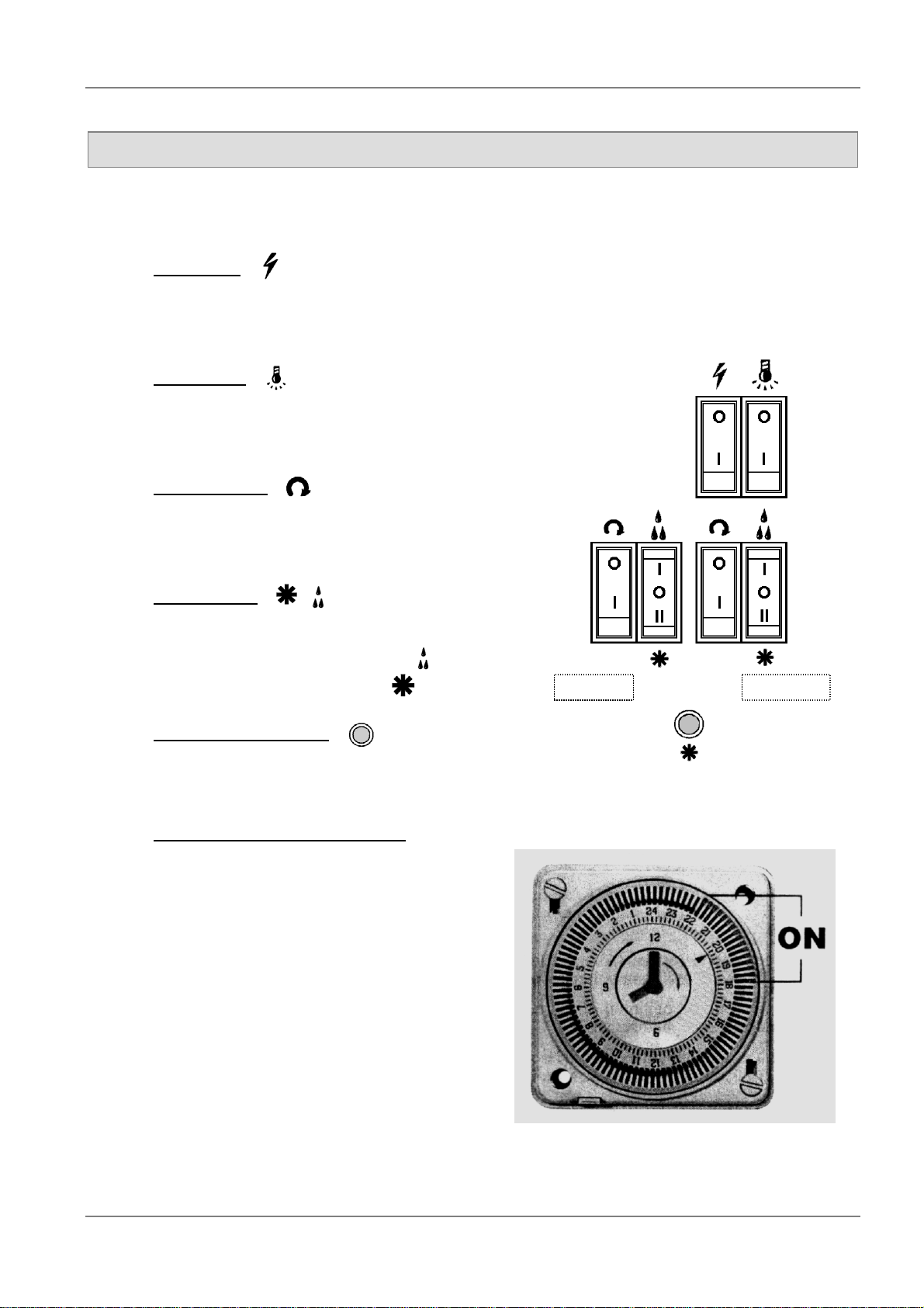
FAMILIARIZING YOURSELF WITH THE CONTROLS
On the right side of the machine are the following switches and controls. (Figure 1)
Main Power
“0” Position: Off position. Power is turned off to all functions.
“I” Position: On position. Machine has power.
Display light
“0” Position: Lights are off.
“I” Position: Lights are on. Display lights have power
Agitator Switch
“0” Position: Agitator is off.
“I” Position: Agitator is on.
Cooler Switch
“0” Position: Off position.
“I” Position: Cool drink mode.
“II” Position: Frozen mode.
/
Left bowl Right bowl
Compressor green light
If the compressor green light is on,
the compressor should be working
Automatic defrost / standby timer
This timer will automatically switch your
dispenser from the frozen drink to the chilled
drink mode. This timer can be programmed to
switch the machine at any time of the day or
night. The standard settings are:
Switch to chilled from frozen – 11:00 PM
Switch to frozen from chilled – 9:00 AM
For all seven days of the week.
Find detailed programming instructions on page
12.
Figure 1
. (Figure 2)
Figure 2
5
Page 6
Granita Machine Operation and Instruction Manual
CLEANING & SANITIZING PROCEDURES
Cleaning is a very important operation to guarantee flavour and the conservation of the product
stored in the bowl.
1 UNLOCK HANDLE LOKING SYSTEM
The machines come from factory with a
handle locking system (fig 3) (locker (3)
not included).
To unlock, remove the locker and pull out
the rod (1) (arrow A).
2 CLEANING THE BOWL
1.1. Turn off all switches and disconnect from
the main power.
Figure 3
1.2. Empty the liquid contents and remove the
lid.
1.3. To remove the bowl, (Figure 4) push
bowl upward (arrow A) taking the bowl
out of the gauge notch (arrows C and D)
and then pull the bowl forward off of the
bowl gasket.
6
Figure 4
Page 7
Granita Machine Operation and Instruction Manual
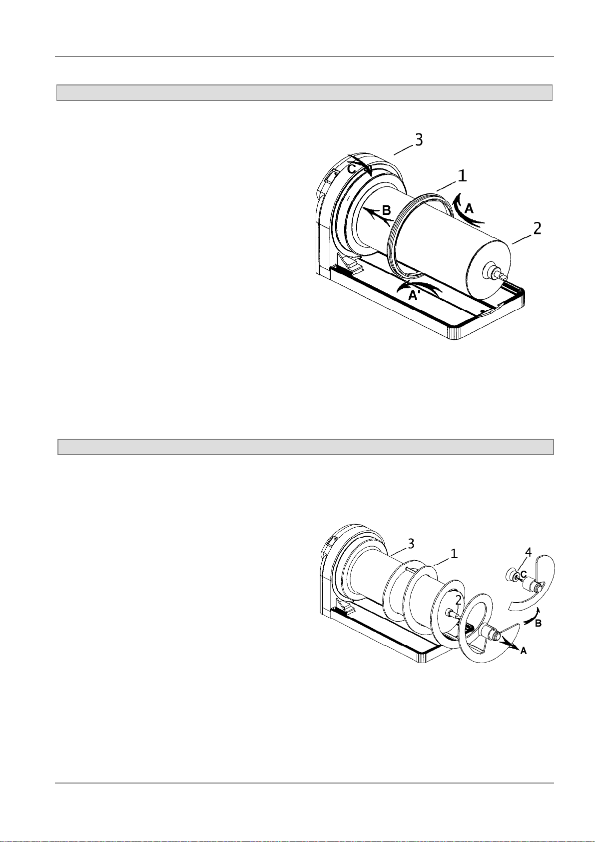
3 CLEANING THE BOWL GASKET
2.1. Once the bowl has been removed,
pull the spiral (Figure 5) forward
(arrow A) and take the head out of
the shaft end (#2).
2.2. On the spiral there is a silicone gasket
(#4) to make the axis leak-proof. Pull
it forward (C) and clean (#4) with
warm water.
4 CLEANING THE SPIRAL
Figure 5
After following the procedures for removing the
spiral, remove the bowl gasket (Figure 6, #1)
from the holder by pulling forward and the
evaporator (#3) will be released for cleaning.
Once all of the elements have been
disassembled proceed to clean with nonabrasive neutral pH detergent. Use a cloth or a
sponge to avoid scratching the bowl and other
elements.
Figure 6
7
Page 8

Granita Machine Operation and Instruction Manual
5 CLEANING THE DRIP TRAY(S)
The front drip tray(s) (Figure 7)
should be emptied daily or more
frequently if necessary. To remove
the drip pan, push the pan slightly
upward (arrow A), then bring it
forward (arrow B) and remove the
grid (arrow C). Put the grid (#2)
back on the tray and place the
spigots (arrows F) in the holes
(arrows D, E and G) on the front
panel (#3).
6 CLEANING THE SPIGOT (Fig.8)
For machines with a handle locking system,
remove the spigot padlock and then take the
locking spigot rod away (#8 – arrow I), remove the
fastener (#7 – arrow J), disconnect the dispensing
handle (#1 – arrow K). By pushing upward (arrow
L), take the spring (#3) out from its holder (#2 –
arrow M), then push the piston downward (#6 –
arrow N), remove the o-ring (#5 – arrow P) and the
special gasket (#4 – arrow Q).
Figure 7
Proceed to clean everything with water and neutral
soap, rinse and reassemble after lubricate without
damaging the gaskets as follows: put in place the
special gasket (#4 – arrow A), put the o-ring (#5)
back in its piston slot (#6 – arrow C), insert the
spring (#3 – arrow D), put the cap in place (#2 –
arrow E), put the handle in place (#1 – arrow F),
insert the fastener (#7 – arrow G), and if you want
to lock the spigot, insert the locking spigot rod (#8
– arrow H) and lock.
8
Figure 8
Page 9

Granita Machine Operation and Instruction Manual
7 REASSEMBLY
Once the machine has been thoroughly cleaned, please follow the directions for reassembling the
machine using previous illustrations.
1. Slide trip trays into place (Figure 7).
2. Reassemble the spigot by reversing the steps
that you performed in (Figure 8). Lubricate with
food grade lubricant parts #4 and #5 (O-ring
and Special gasket) (Figure 9).
3. Assemble the bowl gasket wet (Figure 6).
Assemble the gasket by pulling as arrows A
and A´ indicate and place it in its setting (arrow
C) following the direction of arrow B.
4. Assemble the spiral (Figure 5). Lubricate with
food grade lubricant the silicone gasket (#4)
and insert it in the head of the spiral (C). Insert
the spiral (#1) around the evaporator (#3) and
fit the head in the shaft by turning slightly until it
is placed in its setting.
5. To replace the bowl push backward until the
gauge notch fits in its place inserting the head
of the spiral in the stainless tube end.
Please note
8 CLEANING THE CONDENSER
At least once a month, depending on the working
conditions (presence of dust, grease, etc.) we
recommend to clean the condenser.
First of all, you need to disassemble the left side
panel (2, 3 and 4 bowl model), or the back panel (1
bowl model), by unscrewing them.
Brush off dust and dirt with a soft-bristled brush. Be
careful not do damage the ribs (see Fig. 10).
Please note: a clean condenser is essential to the
operation and longevity of the unit and they should
contact there Local service company for advise on
a preventive maintenance program for this and all
refrigeration equipment.
: The bowl gasket must be wet. This allows the bowl assembly easier.
Figure 9
Figure 10
9
Page 10

Granita Machine Operation and Instruction Manual
HOW TO OPERATE
1. Once the bowl has been cleaned, fill the tank with the desired liquid product (3 gallons). Do not
overfill the tank. NOTE THAT WHEN READY, SLUSH OCCUPIES MORE VOLUME THAN
THE LIQUID (approximately 3.5 gallons of slush). Be sure to consider product ratio (not
exceeding 3 gallons total mix for slush) before mixing or pouring product into tank. IN
ORDER TO KEEP YOUR MACHINE IN GOOD WORKING CONDITION KEEP YOUR
MACHINE FULL.
2. If using natural products as a base (coffee,
lemon juice, orange juice, etc.), it is required
that 5 to 7 oz. of sugar per gallon be added.
Follow the dilution instructions on the bottle. In
general the brix ratio of the product solution
shouldn’t be less than 12.
3. To operate, press main power switch and
agitator switch to ON position (Figure 11).
NOTE: The agitator switch must be to ON
position before setting to liquid or slush
mode.
LEFT RIGHT
3.1 For slush, press the cooler switch to
bottom position ( II / ).
3.2 For liquid, press the cooler switch to up
position ( I / ) . If the machine is being
used as a liquid cooler, it is provided with
an inside thermostat for controlling the
liquid temperature.
Note that your machine is equipped
with a time delay relay that provides for
a four minute delay from the time of the
initial start. This is to prevent the
compressor from short cycling. Once
the compressor is ON, the green light
will be on.
Note: The cooler switch is a three position
switch and in order to have the compressor
off, all the cooler switches need to be in the
middle position.
4. To illuminate the transparency on top of the unit
and the product in the bowl press the display
light switch to down position ( I / ).
CAUTION: IF THE MACHINE IS STOPPED AT
NIGHT WITH ICE IN THE TANK, REMOVE ALL
ICE SLABS BEFORE STARTING.
LEFT
MIDDLE RIGHT
Figure 11
2 bowls
3 bowls
10
Page 11

Granita Machine Operation and Instruction Manual
LIQUID DENSITY ADJUSTEMENT
To adjust the density/consistency of the slush there is an
adjustment knob (Figure 12, #2) at the rear, right corner
of the dispenser (#1).
Turn the knob right (clockwise) or left (counter clockwise)
(arrow C and B) The consistency indicator (#4) will go up
or down (arrow D and E)
To firm up the product, turn the set knob counter
clockwise, which will move the indicator down to a higher
number position
To soften / warm up the product, turn the set knob
clockwise, which will move the indicator up to a lower
number position
NOTE: when using a new product, or on initial start up, it
is recommended that you set the consistency indicator to
the lowest/warmest setting and increase as desired.
Please note that the machines are pre-set at the factory
at a medium setting (number 2.5)
TANK WITH PADLOCK
Fitting the lid over the tank (Figure 13):
Figure 12
1º Slide the rim into the slot situated at the back of the tank.
Lift slightly the front of the lid.
2º Lower the lid and fit onto the tank.
3º Insert the padlock into holes of the front rims of the tank
and the lid. Close it.
Note:
A. The lid can be turned back to front (reversible). Proceed
as above.
B. In order to take off the lid, the padlock must be opened
and released; then follow the instructions in reverse
order
Figure 13
11
Page 12

Granita Machine Operation and Instruction Manual
DEFROST TIMER PROGRAMMING PROCEDURES
COARSE
ADJUSTEMENT
FINE
ADJUSTEMENT
Turn switching dial in the
direction of the arrow until the
current time is almost
opposite the marking arrow F
(here 19.45).
Continue turning the minute
hand in the direction of the
arrow until the current time is
opposite the marking arrow F
(here: 20.00).
12
Page 13

Granita Machine Operation and Instruction Manual
LIST OF COMPONENTS PARTS – Model GHZ-228 SF FREEZING POINT
r
N
Reference Description
1 SL300951200 Full evaporation device
2 SL300970240 Left side panel GB-20/30 UL01
3 SL300970272 Upper tray GB-220 - black
4 SL300310051 Stainless steel screw NFE 27128 M4x10
5 SL300970275 Front panel GB-220 V/2001
6 SL38WZC0005 Output fuse 5 Amp.
7 SL300970233 Condenser SEN122 GHZ 2/3 RP BAF1
8 SL300901135 Full fuse holder
9 SL300310148 Zinc screw DIN 933 M6x10
10 SL300950427 Zinc screw DIN 84 M4x25
11 SL300000233 Ventilator winding Ø 254 x 28º
12 SL37TKU1N16 Motoventilator 16 W. 115/60
13 SL300951202 Electronic regulator 115/60
14 SL300950230 Drainpipe
15 SL300950571 Transformer 50 VA 120V-12V
16 SL300970297 Command side panel GB-220 PRG01
17 SL300951088 Black 20 Amp. switch
18 SL300951253 Green pilot light U.L.
19 SL300951089 Change-over switch
20 SL300970122 Screen for leaking GHZ – chrome
21 SL300970121 Tray for leaking GHZ - chrome
22 SL300970331 Cable with jack cover GB-10
23 SL300310157 Zinc screw DIN 84 M4x20
24 SL300310052 Stainless steel screw NFE 27128 M6x10
25 SL300950583 Zinc screw DIN 7981 B- 3’5x 9’5
26 SL300350467 Full mechanical thermostat
27 SL300970274 Tap screw GB-10 - black
28 SL300951748 Thermostat support GHZ-228 RP UL
29 SL300310271 Zinc nut DIN 934 M6
30 SL300310354 Zinc washer DIN 9021 M6
31 SL300310160 Zinc screw DIN 933 M6x15
32 SL300310322 Zinc screw DIN 7971 B-3’5x21’5
33 SL300950075 Supplement
34 SL37ZG12155 Compressor T2155GK 115/60
35 SL310000411 Full chassis GHZ-228 STN/UL 02
36 SL300951357 Rubber foot H-40 V/99
37 SL300310134 Zinc screw DIN 933 M8x20
38 SL300950265 Zinc scr ew D IN 84 M 5x6
39 SL300950640 Compressor condenser T2155GK 115/60
40 SL300951627 Upper tray tap - black
41 SL300950735 Connection rule PA-44
42 SL300950737 Connection rule complement PA-52
43 SL300950568 Special nut N901034 M4
44 SL300951457 Evaporation device support cover GHZ - chrome
45 SL310000320 Evap. device support GHZ PZ-1 - black
46 SL300310042 Stainless steel screw DIN 963 M4x12
47 SL300950587 Full miniruptor V/99
48 SL300950810 Zinc screw DIN 7971 B-2’5x25
r
N
Reference Description
49 SL310000321 Evap. device support GHZ PZ-2 - black
50 SL300950760 Zinc screw DIN 7971 B-2’9 x 13
51 SL310000103 Short regulation rod GHZ-14 V/99 - black
52 SL3GS12036A Holding in place of regulation system
53 SL3GS12037B Regulation system spring guide
54 SL300950116 Regulation spring GHZ-14
55 SL300950833 Nut supplement foot
56 SL300310203 Stainless steel nut DIN 934 M4
57 SL300950445 Zinc screw DIN 7971 B-2’9 x 9’5
58 SL300970155 Electrovalve clamp V/99
59 SL300951264 Electrovalve bobbin 115/60
60 SL300970159 Double electrovalve body V/99
61 SL3GS24711D Full double electrovalve 115/60
62 SL300970239 Back panel GB-220 V/2001
63 SL300970242 Right side panel GB-20/30 V2001
64 SL300310141 Zinc scre w DIN 84 M3 x25
65 SL300951101 Double electrovalve support deck
66 SL300950428 Device distancing back panel
67 SL300950624 Adjustable supplement foot V/US
68 SL300950641 Compressor relay T2155GK 115/60
69 SL300950642 Compressor klixon T2155GK 115/60
70 SL300500118 Pass cable PA-107
71 SL300310101 Zinc screw DIN 933 M8x35
72 SL300310255 Zinc washer DIN 125 M10
73 SL300310205 Zinc nut DIN 934 M8
74 SL300950746 Zinc screw DIN 933 M6x50
75 SL300951921 Zinc screw DIN 7981 B-3’9x13
76 SL300310320 Zinc screw DIN 7971 B-2’2x7
77 SL300310353 Zinc washer DIN 125 M6
78 SL300950798 Tran sformer cover
79 SL300950759 Zinc screw DIN 933 M6x12
80 SL300970276 Command side panel cover - black
81 SL38GZDG060 Transformer washer
82 SL300970294 Bolt cove r - black
83 SL300310250 Brass nut DIN 934 M6
84 SL300950649 Brass washer DIN 125 M6
85 SL300950648 Brass screw DIN 933 M6x25
86 SL300950210 Zinc screw DIN 933 M4x45
87 SL300901578 Zinc washer DIN 125 M4
88 SL300951368 Supplement foot tap V/US
89 SL300950840 Full adjustable foot V/US
90 SL300951412 Lock ing
91 SL310000400 Locking special screw
92 SL300970277 Daily hourly timer
93 SL300951365 Relay 115V/60Hz
94 SL300900005 Zinc nut DIN 934 m3
95 SL300951694 Obturator
13
Page 14

Granita Machine Operation and Instruction Manual
EXPLODED VIEW – Model GHZ-228 SF FREEZING POINT
14
Page 15

Granita Machine Operation and Instruction Manual
LIST OF COMPONENTS PARTS – Model GHZ-342 FF FREEZING POINT
Nr Reference Description
1 SL300950585 Full evaporation device
2 SL300970240 Left side panel GB-20/30 UL 01
3 SL300970273 Upper tray GB-330 – black
4 SL300310051 Stainless steel screw NFE 27128 M4x10
5 SL300970245 Front panel GB-330 V/2001
6 SL38WZC0005 Output fuse 5 Amp.
7 SL300970233 Condenser SENC0122 GHZ 2/3 RP BAF1
8 SL300901135 Fuse holder 5x20
9 SL300906167 Zinc nut DIN 934 M5
10 SL300310355 Zinc washer DIN 125 M5
11 SL300000233 Ventilator winding Ø 254 x 28º
12 SL37TKU1N16 Motoventilator 16 W. 115/60
13 SL300951202 Electronic regulator 115/60
14 SL300950230 Drainpipe
15 SL300950572 Transformer 60VA 120V/12V
16 SL300970298 Command side panel GB-330 PRG01
17 SL300951088 Black 20 Amp. switch
18 SL300951253 Green pilot light
19 SL300951089 Black change-over switch
20 SL300970122 Screen for leaking GHZ – chrome
21 SL300970121 Tray for leaking GHZ - chrome
22 SL300970331 Cable with jack cover GB-10
23 SL300310157 Zinc screw DIN 84 M4x20
24 SL300310052 Stainless steel screw NFE 27128 M6x10
25 SL300950583 Zinc screw DIN 7981 B-3’5x9’5
26 SL300310179 Zinc screw DIN 84 M5x15
27 SL300350467 Full mechanical thermostat
28 SL300950448 Thermostat support GHZ-342 V/95
29 SL300310271 Zinc nut DIN 934 M6
30 SL300310354 Zinc washer DIN 9021 M6
31 SL300310160 Zinc screw DIN 933 M6x16
32 SL300310322 Zinc screw DIN 7971 B-3’5x21’5
33 SL300950075 Supplement
34 SL300951256 Compressor T2178GK 115/60
35 SL310000426 Full chassis GHZ-342 STN/UL 02
36 SL300951357 Rubber foot GHZ-14 V/99
37 SL300310134 Zinc screw DIN 933 M8x20
38 SL300950210 Zinc screw DIN 933 M4x45
39 SL300951257 Compressor condenser T2178GK 115/60
40 SL300951627 Upper tray tap - black
41 SL300950735 Connection rule PA-44
42 SL300950737 Connection rule complement PA-52
43 SL300950568 Special nut N901034 M4
44 SL300951457 Evaporation device support cover GHZ - chrome
45 SL310000320 Evap. device support GHZ PZ-1 - black
46 SL300310042 Stainless steel screw DIN 963 M4x12
47 SL300950587 Full miniruptor V/99
48 SL300950810 Zinc screw DIN 7971 B-2’5x25
49 SL310000321 Evap. device support GHZ PZ-2 - black
50 SL300950760 Zinc screw DIN 7971 B-2’9x13
51 SL310000103 Short regulation rod GHZ-14 - black
Nr Reference Description
52 SL3GS12036A Holding in place of regulation system
53 SL3GS12037B Regulation system spring guide
54 SL300950116 Regulation spring GHZ-14 - hard
55 SL300950833 Nut supplement foot
56 SL300310203 Stainless steel nut DIN 934 M4
57 SL300950265 Zinc scre w DIN 84 M5 x6
58 SL300970155 Electrovalve clamp V/99
59 SL300951264 Electrovalve bobbin 115/60
60 SL300970157 Triple electrovalve body V/99
61 SL3GS36711D Full triple electrovalve 115/60 V/99
62 SL300970246 Back panel GB-330 V/2001
63 SL300970242 Right side panel GB-20/30 V2001
64 SL300310141 Zinc scre w DIN 84 M3 x25
65 SL300951101 Double electrovalve support deck
66 SL300950428 Device distancing back panel
67 SL300950624 Adjustable supplement foot V/US
68 SL300951258 Compressor relay T2178GK 115/60
69 SL300951259 Condenser running T2178GK 115/60
70 SL300500118 Pass cable PA-107
71 SL300310101 Zinc screw DIN 933 M8x35
72 SL300310255 Zinc washer DIN 125 M10
73 SL300310205 Zinc nut DIN 934 M8
74 SL300950746 Zinc screw DIN 933 M6x50
75 SL300950427 Zinc scre w DIN 84 M4 x25
76 SL300950759 Zinc screw DIN 933 M6x12
77 SL300310353 Zinc washer DIN 125 M6
78 SL300310320 Zinc screw DIN 7971 B-2’2x7
79 SL300951368 Antiskid supplement foot tap
80 SL300901578 Zinc washer DIN 125 M4
SL38GZDG06
81
82 SL300950798 Tran sformer cover
83 SL300310250 Brass nut DIN 934 M6
84 SL300950649 Brass washer DIN 125 M6
85 SL300950648 Brass screw DIN 933 M6x25
86 SL37TBH1411 Motoventilator 120x120x38 20/50
87 SL300950445 Zinc screw DIN 7971 B-2’9 x 9’5
88 SL300950840 Full adjustable foot V/US
89 SL300970294 Bolt cove r - black
90 SL300970276 Command side panel cover - Black
91 SL300951575 Operation box compressor T2180GK
92 SL300950035 Condenser SENC0014 GHZ-114/456
93 SL300970274 Tap screw GB-10 - black
94 SL300970277 Daily hourly timer
95 SL300951365 Relay 115/60
96 SL300900005 Zinc nut DIN 934 M3
97 SL300310148 Zinc screw DIN 933 M6x10
98 SL300951412 Loking
99 SL310000400 Locking special screw
100 SL300951694 Pass cable 31583
101 SL300951921 Zinc screw DIN 7981 B-3'9x13
102 SL300970091 Spacer front panel GB
Transformer washer
15
Page 16

Granita Machine Operation and Instruction Manual
EXPLODED VIEW – Model GHZ-342 FF FREEZING POINT
16
Page 17

Granita Machine Operation and Instruction Manual
WIRING DIAGRAM – Model GHZ-228 SF FREEZING POINT
Number
Description
Number
Description
1 General switch
2 Electronic regulator
3 Compressor pilot light
4 Compressor
5 Motor ventilator
6 Bowls light switch
7 Transformer
8 Full fuse holder
9 Bowls light
10 Left shovels switch
11 Engine for left shovels
12 Left liquid/iced drink switch
13 Left mechanical thermostat
14 Left micro regulation
15 Left electrovalve
16 Switch relays
17 Right shovels switch
18 Engine for right shovels
19 Right liquid/iced drink switch
20 Right mechanical thermostat
21 Right micro regulation
22 Right electrovalve
23 Hourly timer
24 Compressor klixon
25 Compressor relay
26 Connector lights
27 Socket display lamp
17
Page 18

Granita Machine Operation and Instruction Manual
WIRING DIAGRAM – Model GHZ-342 FF FREEZING POINT
Number
Description
Number
Description
1 General switch
2 Electronic regulator
3 Compressor pilot light
4 Compressor
5 Motor ventilator 1
6 Bowls light switch
7 Transformer
8 Full fuse holder
9 Bowls light
10 Left shovels switch
11 Engine for left shovels
12 Left liquid/iced drink switch
13 Left mechanical thermostat
14 Left micro regulation
15 Left electrovalve
16 Switch relay
17 Central shovels switch
18 Engine for central shovels
19 Central liquid/iced drink switch
20 Central mechanical thermostat
21 Central micro regulation
22 Central electrovalve
23 Right shovels switch
24 Engine for right shovels
25 Right liquid/iced drink switch
26 Right mechanical thermostat
27 Right micro regulation
28 Right electrovalve
29 Hourly timer
30 Compressor klixon
31 Compressor relay
32 Connector lights
33 Socket display lamp
34 Motor ventilator 2
18
Page 19

Granita Machine Operation and Instruction Manual
WATERTIGHTNESS AND TRANSMISSION ELEMENTS
Number Reference Description
1 SL300951752 Evaporator cap GHZ-14 2001
2 SL300951857 Watertight shaft joint GHZ-14 2002
3 SL310000104 Tank joint - black
4 SL3GS12030A Beater Drive Shaft
5 SL300950254 Shocked DIN 471 E-12
6 SL300950321 Transmission shaft racor GHZ-14 V/95
7 SL3MS4M015C Gear motor
Only parts with numbers will be stock items;
others will be special ordered.
COVER GHZ
Number
Reference Description
1 SL310001057 Reversible top cover GHZ chrome
2 SL300951706 Transparency GHZ beach
3 SL3GS24317A Lamp holder B-15-S
4 SL300950100 Lamp 21W. 12V.
5 SL300950679 Neutral cable EURO
6 SL300950583 Zinc screw DIN 7981 B- 3’5x 9’5
7 SL300970252 Full cable cover
8 SL300310633 Wing passes DIN 94 2x5
9 SL300950646 Connection rule Ø4
10 SL300951583 Cover under base GHZ v/padlock
11 SL300951595 Transparency support cover GHZ
12 SL310001056 Full tank rev. cover GHZ - chrome
19
Page 20

Granita Machine Operation and Instruction Manual
SPIRAL SHOVEL
Number Reference Description
1 SL3GS12009D Full spiral shovel
TANK AND SHOVEL GUIDE
Number Reference Description
1 SL300951582 Tank GHZ v/padlock
2 SL300951369 Padlock (optional)
20
Page 21

Granita Machine Operation and Instruction Manual
FULL TAP PULL
Number Reference Description
1 SL300951671 Dispensing handle GHZ PULL - black
2 SL300951672 Tap spring cap GHZ PULL - black
3 SL300951647 Tap spring GHZ PULL - hard
4 SL310000105 Piston special gasket - black
5 SL310000106 Tap gasket - black
6 SL310000089 Tap piston GHZ PULL - black
7 SL300951670 Tap fastener GHZ PULL - black
SL300970279 Locking tap rod GB-220 - black
8
2
21
Page 22

Granita Machine Operation and Instruction Manual
TROUBLE SHOOTING GUIDE
Trouble Possible Causes Remedy
Machine overheats • Machine vents are blocked • Check that nothing is obstructing the
vents
The tap drips • O-rings may be improperly
placed
Machine is not cooling the
product*
The unit does not work • No power
• Voltage may be labelled
improperly
• Does the machine have
power?
• The condenser is dirty
• No refrigerant
• Switch Power cord loose or
damaged
• Defective
• Wiring disconnected
• Make sure that the o-rings are in place
and have no cuts.
• Check that the piston is correctly closed
and nothing is obstruction its outlet.
• Verify that the spring works correctly.
• Verify that the voltage supply matches
the label on the back of the machine.
• Check to see if the machine is plugged
in.
• Clean the condenser carefully with a
brush trying not to damage the ribs.
See figure 7.
• Contact authorized service agency.
• Connect unit to power supply.
• Locate problem and correct. Replace
power cord if necessary.
• Replace switch.
• Check wiring for loose connection or
broken wire.
One of the augers does not
work
No pilot light when unit is on • Defective wiring connection
Compressor does not start • Defective overload
• Motor connection loose
• Defective switch
• Auger is stuck
• Bad gear reducer motor
• Defective density switch
• Burned out bulb
• Defective thermostat
• Defective relay
• Defective compressor
22
• Check wiring to motor.
• Replace switch.
• Check auger, replace if necessary.
• Replace.
• Check wiring.
• Check switch.
• Replace bulb.
• Replace thermostat.
• Replace.
• Replace.
• Replace.
Page 23

Granita Machine Operation and Instruction Manual
TROUBLE SHOOTING GUIDE (cont’d)
Trouble Possible Causes Remedy
Unit cools but does not
freeze
One bowl does not cool* • Defective solenoid valve
One bowl cools but does not
freeze*
Noisy auger • No lubricant
• Switch is not on
• The condenser is dirty
• Not enough air around the unit
• Less than 12% sugar content
• Density switch at lower level
off
• Defective thermostat
• Defective density switch
• Defective front panel switch
• Density switch at lower level
defective
• Front panel switch set for
liquid
• Defective gear reducer motor
• Check that switch is on right position.
• Clean the condenser carefully with a
brush (do not to damage the ribs).
• Remove other objects that may be
blocking airflow around unit.
• Remix with 12% sugar content.
• Turn on density switch.
• Replace.
• Replace.
• Replace.
• Replace.
• Replace.
• Check that switch is in right position.
• Lubricant auger.
• Replace.
Drippy nozzle or valve • O-Rings worn or defective • Replace O-Rings.
Leaky Bowl • Gasket improperly installed or
defective
Cover light does not work • Burned out bulb
• Defective cable
• Defective plug
• Defective fuse
• Defective transformer
• Defective light switch
• Reinstall gasket, replace if necessary.
• Replace bulb.
• Replace cable.
• Replace plug.
• Replace fuse.
• Replace transformer.
• Replace switch
23
 Loading...