

Page 1

APPLICARE
TARGA
CARATTERISTICHE
INSTRUCTIONS HANDBOOK
191 BAR USA
Page 2

191 BAR USA
:enoizidE 4 :ataD 20/90 :ehcifidoM 4.zeS,3.zeS,1.zeS
:ottadeR MA :otacifireV FA :otavorppA VR
We wish to thank you for the preference granted to us by purchasing one of
CARPIGIANI machines.
To the best guarantee, since 1993 Carpigiani has submitted its own Quality
System to the certification according to the international Standard ISO 9001-94 .
Moreover, Carpigiani machines comply with following European Directives:
• 98/37/CE “Machinery” Directive;
• 73/23/CEE “Low Voltage” Directive;
• 89/336/CEE “Emc” Directive;
• 97/23/CE “Ped” Directive;
• 2004/1935/CE
CARPIGIANI
Via Emilia, 45 - 40011 Anzola Emilia (Bologna) - Italy
Tel. 051-6505111 - Fax 051-732178
Relating to “Materials and articles in contact with foodstuffs”
This handbook may not be reprinted, transferred, registered, recorded in a retrieval system, nor
translated in other languages unless otherwise previously agreed with CARPIGIANI.
The purchaser has the wright to reprint it for his own office use.
CARPIGIANI policy pursues a steady reasearch and development, thus it reserves the right to
make changes and revisions whenever deemed necessary and without being bound to previous
statements to the purchaser.
191 bar usa_G - 09/02 - ed. 4
2
Page 3

INDEX
FOREWORD ...................................................................................... 5
INSTRUCTION HANDBOOK .................................................................................. 5
PURPOSE ................................................................................................................... 5
HANDBOOK STRUCTURE ..................................................................................... 5
ADDITIONAL DOCUMENTATION ....................................................................... 5
CONVENTIONAL SYMBOLS ................................................................................. 6
SAFETY ..................................................................................................................... 7
QUALIFICATION OF THE STAFF ......................................................................... 7
WARNING ................................................................................................................. 7
1 GENERAL ..................................................................................... 9
1.1 GENERAL INFORMATION ............................................................................ 9
1.1.1 MANUFACTURER'S IDENTIFICATION DATA ..................................... 9
1.1.2 INFORMATION ABOUT SERVICE ......................................................... 9
1.1.3 INFORMATION TO THE USERS ............................................................. 9
1.2 INFORMATION ABOUT THE MACHINE ................................................... 9
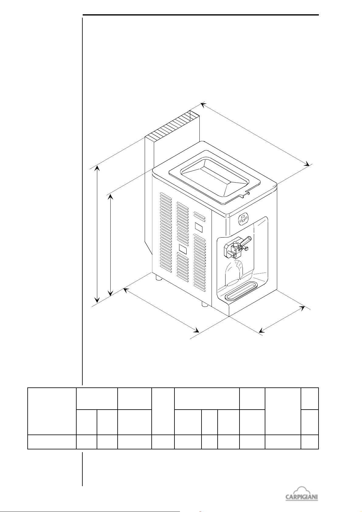
1.2.1 GENERAL DATA ....................................................................................... 9
1.2.2 MACHINE LAY-OUT .............................................................................. 10
1.2.3 TECHNICAL FEATURES ........................................................................ 10
1.2.4 MACHINE SETS LOCATION ................................................................ 11
1.3 INTENDED USE .............................................................................................. 11
1.4 NOISE ................................................................................................................ 11
1.5 STORING A MACHINE ................................................................................. 11
1.6 DISPOSAL OF PACKING STUFFS .............................................................. 11
1.7 WEEE (WASTE ELECTRICAL AND ELECTRONIC EQUIPMENT) ... 11
191 BAR USA
2 INSTALLATION .......................................................................... 13
2.1 ROOM NECESSARY TO THE MACHINE USE ........................................ 13
2.2 MACHINE WITH AIRCOOLED CONDENSER ........................................ 13
2.3 MACHINE WITH WATERCOOLED CONDENSER ................................. 13
2.3.1 WATER VALVE ADJUSTMENT ............................................................ 14
2.4 ELECTRIC CONNECTION ........................................................................... 14
2.4.1 REPLACEMENT OF POWER SUPPLY CORD ..................................... 14
2.5 LOCATION ...................................................................................................... 14
2.6 REFILLING ..................................................................................................... 14
2.7 MACHINE TESTING ..................................................................................... 14
3 DIRECTION FOR USE .............................................................. 15
3.1 MACHINE CONFIGURATION ..................................................................... 15
3.2 ELECTRONIC CONTROL KEYBOARD AND BUTTON FUNCTIONS .......... 15
3.3 SPIGOT HANDLE .............................................................................................. 16
3.4 PUMP-FEED MACHINE - "R" PUMP ................................................................ 17
3.5 GRAVITY-FEED MACHINE - FEEDING NEEDLE ............................................. 17
3.6 PRELIMINARY OPERATION, WASHING AND SANITIZATION .................. 18
3.6.1 CLEANING ................................................................................................... 18
3.6.2 SANITIZING ................................................................................................ 20
3.6.3 HYGIENE ...................................................................................................... 20
3.7 STARTING THE MACHINE .............................................................................. 21
3.7.1 STARTING MACHINES WITH PUMP ........................................................ 21
3.7.2 STARTING GRAVITY-FED MACHINES ..................................................... 21
3.8 PRODUCTION ................................................................................................... 22
3.9 OPEN PROCEDURE .......................................................................................... 22
3.9.1 START THE MACHINE .............................................................................. 22
3.10 CLOSE PROCEDURE ..................................................................................... 22
3.11 ON THE DISPLAY .......................................................................................... 22
3.12 PROGRAMMING FOR USER ........................................................................ 23
3
191 bar usa_G - 09/02 - ed. 4
Page 4

191 BAR USA
4 SAFETY DEVICES ...................................................................... 25
4.1 ALARMS ............................................................................................................ 25
4.1.1 BLACK OUT ................................................................................................ 26
5 DISASSEMBLING, WASHING, SANITIZING AND REASSEMBLING
THE PARTS IN CONCTACT WITH THE PRODUCT ........ 27
5.1 PROGRAMMED CLEANING ............................................................................ 27
5.1.1 CLEANING ................................................................................................... 27
5.2 EMPTYING THE ICE CREAM PLANT .............................................................. 27
5.3 PUMP FED MACHINES - DISASSEMBLING MIX PUMP ................................ 28
5.4 GRAVITY FED MACHINES - DISASSEMBLING FEEDING NEEDLE .............. 28
5.5 DISASSEMBLING OF THE DISPENSING DOOR ............................................ 29
5.6 PUMP FED MACHINES - DISASSEMBLING BEATER .................................... 29
5.7 GRAVITY FED MACHINES - DISASSEMBLING BEATER .............................. 29
5.8 WASHING AND SANITIZING OF COMPONENT PARTS .............................. 30
5.9 PUMP FED MACHINES - REASSEMBLING MIX PUMP .................................. 30
5.10 GRAVITY FED MACHINES - REASSEMBLING FEEDING NEEDLE ............. 31
5.11 PUMP FED MACHINES - REASSEMBLING BEATER ................................... 31
5.12 GRAVITY FED MACHINES - REASSEMBLING BEATER ............................. 32
5.13 REASSEMBLING OF THE DISPENSING DOOR ........................................... 32
5.14 SANITIZING THE WHOLE MACHINE ........................................................... 32
5.15 MIX PRIMING .................................................................................................. 33
6 MAINTENANCE ......................................................................... 35
6.1 SERVICING TYPOLOGY .............................................................................. 35
6.2 WATERCOOLING .......................................................................................... 36
6.3 AIRCOOLING .................................................................................................. 36
6.4 TABLE OF SPARE PARTS EQUIPMENT .................................................. 37
7 TROUBLESHOOT GUIDE ........................................................ 39
191 bar usa_G - 09/02 - ed. 4
4
Page 5
FOREWORD
INSTRUCTION HANDBOOK
Editing this handbook, it was taken into due account European Community directions on safety
standards as well as on free circulation of industrial products within E.C.
PURPOSE
This handbook was conceived taking machine users' needs into due account.
Topics relevant to a correct use of the machine have been analyzed in order to keep unchanged in
the long run quality features charachterizing CARPIGIANI machines all over the world.
A significant part of this handbook refers to the conditions necessary to the machine use and to the
necessary procedure during cleanout as well as routine and special maintenance.
Nevertheless, this handbook cannot meet all demands in details. In case of doubts or missing
information, please apply to:
CARPIGIANI Via Emilia, 45 - 40011 Anzola Emilia (Bologna) - Italy
Tel. 051- 6505111 - Fax 051-732178
HANDBOOK STRUCTURE
This handbook is divided in sections, chapters and subchapters in order to be consulted more easily.
191 BAR USA
SECTION
A section is the part of the handbook identifying a specific topic related to a machine part.
CHAPTER
A chapter is that part of a section describing an assembly or concept relevant to a machine part.
SUBCHAPTER
It is that part of a chapter detailing the specific component of a machine part.
It is necessary that each person involved in the machine operation reads and clearly understands
those parts of the handbook of his/her own concern, and particularly:
- The Operator must read the chapters concerning the machine star-up and the operation of
machine components.
- A skilled technician involved in the installation, maintenance, repair, etc., of the machine
must read all parts of this handbook.
ADDITIONAL DOCUMENTATION
Along with an instruction manual, each machine is supplied also with additional documentation:
- Part list: A list of spare parts which is delivered together with the machine for its maintenance.
- Wiring diagram: A diagram of wiring connections is placed in the machine.
ATTENTION
Before using the machine read carefully the instruction handbook.
Pay attention to the safety instructions.
5
191 bar usa_G - 09/02 - ed. 4
Page 6
191 BAR USA
CONVENTIONAL SYMBOLS
CAUTION: ELECTRIC SHOCK DANGER
The staff involved is warned that the non-obsevance of safety rules in carrying out the operation
described may cause an electric shock.
CAUTION: GENERAL HAZARD
The staff involved is warned that the operation described may cause injury if not performed
following safety rules.
NOTE
It points out significant information for the staff involved.
WARNINGS
The staff involved is warned that the non-observance of warning may cause loss of data and
damage to the machine.
PROTECTIONS
This symbol on the side means that the operator must use personal protection against an implicit
risk of accident.
QUALIFICATION OF THE STAFF
MACHINE OPERATOR
He/she is an unskilled person, who has no specific expertise and can only carry out easy chores,
such as the machine operation by means of controls available on the push-button panel, and filling
and drawing of products used during operations.
MAINTENANCE ENGINEER
He/she is a skilled engineer for the operation of the machine under normal conditions; he/she is
able to carry out interventions on mechanical parts and all adjustments, as well as maintenance
and repairs. He/she is qualified for interventions on electrical and refrigeration components.
CARPIGIANI ENGINEER
He/she is a skilled engineer the manufacturer assigned to field interventions for complex jobs
under particular conditions or in accordance with agreements made with the machine's owner.
191 bar usa_G - 09/02 - ed. 4
6
Page 7
SAFETY
When using industrial equipment and plants, one must be aware of the fact that drive mechanisms
(rotary motion), high voltage components, as well as parts subject to high temperatures may cause
serious damage to persons and things.
Who is in charge of plant safety must be on the look-out that
- An incorrect use or handling shall be avoided
- Safety devices must neither be removed nor tampered with
- The machine shall be regularly serviced
- Only original spare parts are to be used especially as far as those components with safety
functions are concerned (ex.: protection microswitches, thermostats).
To achieve the above, the following is necessary:
- At the working place an instruction manual relevant to the machine should be available.
- Such documentation must be carefully read and requirements must conse quently be met.
- Only adequately skilled personnel should be assigned to electrical equipment.
- Be on the look out that no technician will ever carry out interventions outside his own
knowledge and responsibility sphere.
QUALIFICATION OF THE STAFF
Staff attached to the machine can be distinguished according to training and responsibility as
follows:
191 BAR USA
OPERATOR
- A person who has not necessarily a high technical knowledge, just trained for ordinary operation
of the machine, such as: startup, stop, filling, basic maintenance (cleanout, simple blocking,
instrumentation checkings, etc.).
SKILLED ENGINEER
- A person enganged on more complicated operations of installation, maintenance, repairs, etc.
IMPORTANT!
One must be on the look-out that the staff does not carry out any operation outside its own sphere
of konwledge and responsibility.
NOTE:
According to the standard at present in force, a SKILLED ENGINEER is who, thanks to
- training, experience and education,
- knowledge of rules, prescriptions and interventions on accident prevention,
- knowledge of machine operating conditions,
is able to realize and avoid any danger and has also been allowed by the person in charge of plant
safety to carry out all kinds of interventions.
WARNING
When installing the machine, insert a differential magnetothermal protection switch on all poles
of the line, adequately sized to the absorption power shown on machine data plate and with contact
opening of 3 mm at least.
• Never put your hand into the machine, alike during production and cleaning operations.
Before carrying out any maintenance operation, make sure that the machine is in “STOP”
position and main switch has been cut out.
• It is forbidden to wash the machine by means of a bolt of water under pressure.
• It is forbidden to remove panels in order to reach the machine inside before having
disconnected the machine.
• CARPIGIANI is not responsible for any accident that might happen during operation,
cleaning and/or servicing of its units, if this warning has not been fully complied with.
7
191 bar usa_G - 09/02 - ed. 4
Page 8

191 BAR USA
191 bar usa_G - 09/02 - ed. 4
8
Page 9
1 GENERAL INFORMATION
1.1 GENERAL INFORMATION
1.1.1 Manufacturer's identification data
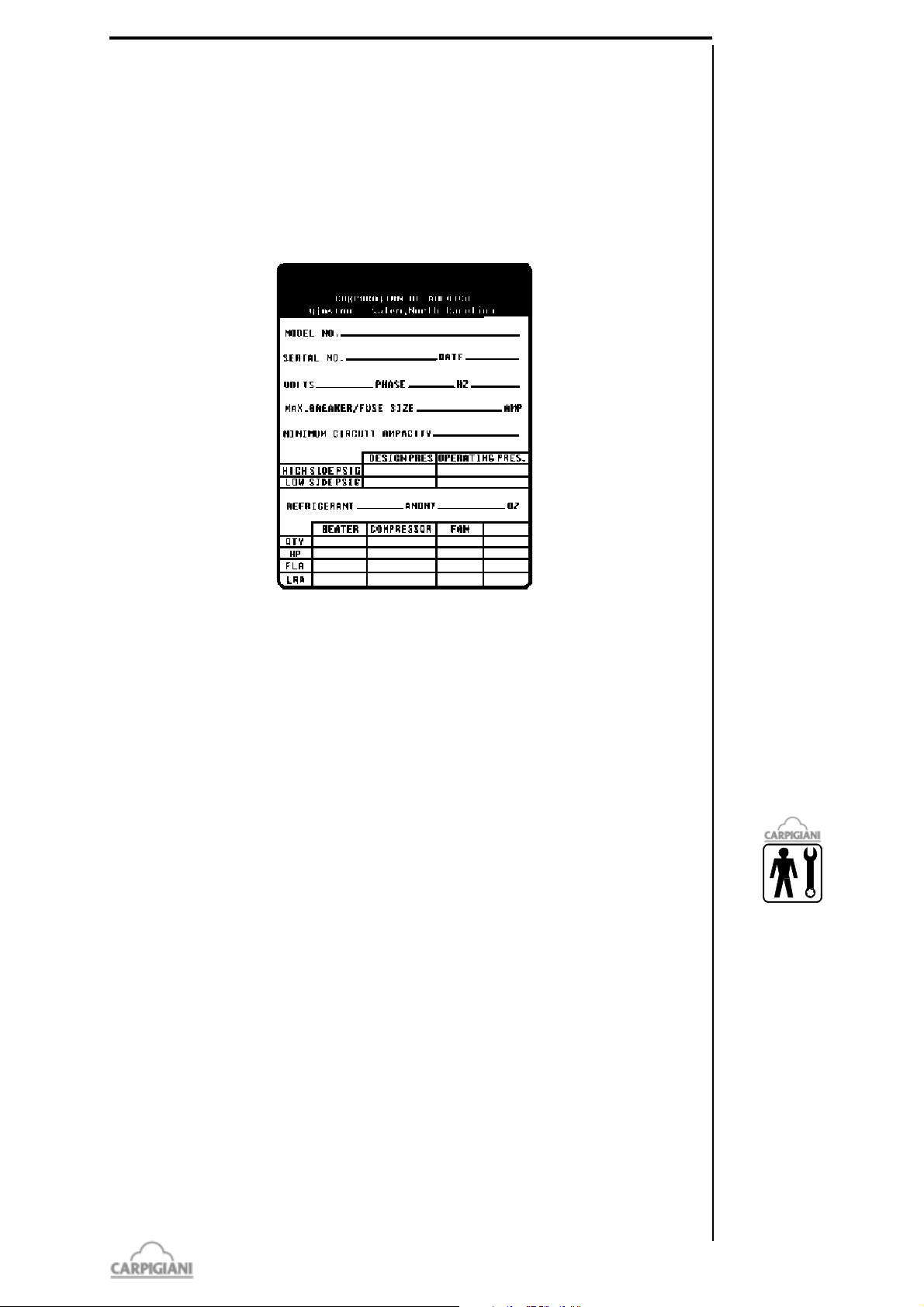
The machine has a data plate carrying manufacturer data, machine type and serial number, assigned
when it is manufactured.
Copy of machine data plate to be found on first page of this handbook.
191 BAR USA
1.1.2 Information about service
All operations of routine maintenance are here described in section "Maintenance"; any additional
operation requiring technical intervention on the machine must be cleared with the manufacturer,
who will also examine the possibility of a factory technician field intervention.
1.1.3 Information to the user
l The manufacturer of the machine is at user's disposal for any explanation and information about
the machine operation.
l In case of need, please call the local distributor, or the manufacturer if no distributor is available.
l Manufacturer's service department is available for any information about operation, and
requests of spare parts and service.
1.2 INFORMATION ABOUT THE MACHINE
1.2.1 General data
Counter-top machine to immediately produce and distribute soft express ice cream in one flavor
available with pump or grabity feeder.
CARPIGIANI recommends to always use high quality mix for ice cream production in order to
satisfy your customers, even the most hard-to-please ones. Any saving made to the prejudice of
quality will surely turn into a loss much bigger than the saving itself.
9
191 bar usa_G - 09/02 - ed. 4
Page 10
191 BAR USA
710 mm (28 in)
810 mm (31 in)
5
0
5
m
m
(
2
0
i
n
)
6
8
4
m
m
(
2
7
i
n
)
6
7
5
m
m
(
2
6
i
n
)
LEDOM
ylruoH
*noitcudorp
yticapacknaT
sruovalF
ylppusrewoP
rewoP
tupni
resnednoC
teN
thgieW
bl
zo7,2
snoitrop
.laG tloV Zh sesahP pH bl
RAB191 24 052 7,4 1 032-802 06 1 4,2 retaw/ria 032
Bearing in mind the above statements, please take heed of the following suggestions:
- Make your mixes yourselves from high quality natural ingredients or buy them from reliable
companies.
- Follow closely instructions given by your mix supplier for the preparation of the mixes.
- Do not alter your mix supplier's recipies, by adding, for instance, water or sugar.
- Taste ice cream before serving it and start selling it only if entirely satisfactory.
- Make sure your staff always keeps the machine clean.
- Have your machine serviced always by companies authorized by CARPIGIANI.
1.2.2 Machine layout
191 bar usa_G - 09/02 - ed. 4
1.2.3 Technical features
* Hour output may vary depending on mix used
Performances featured by a room temperature of 77°F and a water temperature of 68°F.
10
Page 11
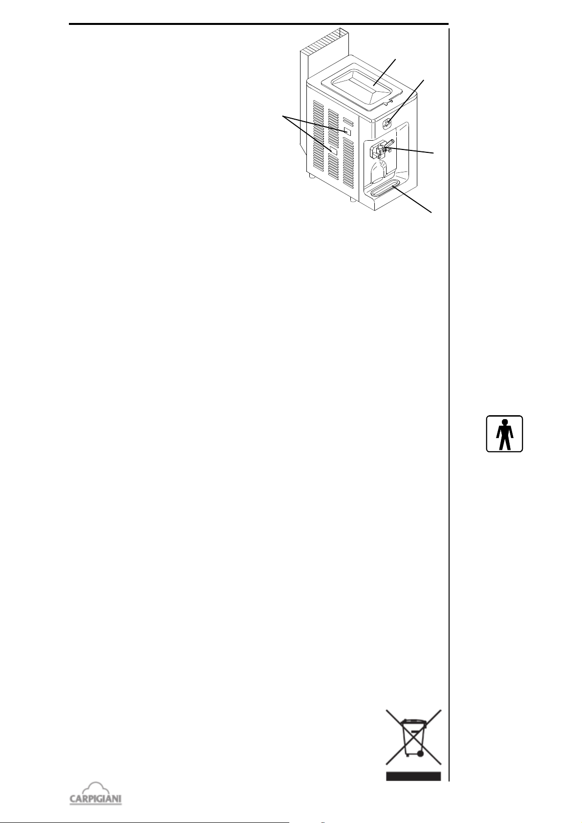
1.2.4 Machine sets location
191 BAR USA
caption:
1 control panel
2 Freezing cylinder front lid
3 Drip tray shelf
4 Mix tank cover
5 Drip troughs
5
4
1
3
1.3 INTEDED USE
The machines must be used solely for the purpose described in chapter 1.2.1, "General information"
within the functional limits decribed below.
Voltage ±10%
Min air temperature °F 50°F
Max air temperature °F 109°F
Min water temperature 50°F
Max water temperature 86°F
Min. water pressure 0,1 MPa (1 bar)
Max water pressure 0,8 MPa (8 bar)
Max relative humidity 85%
2
The machine has been designed for its use in places which are not subject to explosion-proof
standards; its use is thus bound to conforming places and normal atmospher
1.4 NOISE
The steady acoustic pressure level weighed A in a working place alike by watercooled and by
aircooled machines is less than 70 dB(A).
1.5 STORING A MACHINE
The machine must be stored in a dry and dump-free place.
Before storing the machine, wrap it in a cloth in order to protect it against dust and else.
1.6 DISPOSAL OF PACKING STUFFS
When opening the packing crate, divide packing stuffs per type and get rid of them according to laws
in force in machine installation country.
1.7 WEEE (Waste Electrical and Electronic Equipment)
In accordance with European Directive 2002/96/EC on WEEE (Waste Electrical and
Electronic Equipment), the presence of the above symbol on the product or on its packaging
indicates that this item must not be disposed of in the normal unsorted municipal waste stream.
Instead, it is the user’s responsibility to dispose of this product by returning it to a collection
point designated for the recycling of electrical and electronic equipment waste.
Separate collection of this waste helps to optimize the recovery and recycling
of any reclaimable materials and also reduces the impact on human health and
the environment.
For more information concerning the correct disposal of this product, please
contact your local authority or the retailer where this product was purchased.
11
191 bar usa_G - 09/02 - ed. 4
Page 12

191 BAR USA
191 bar usa_G - 09/02 - ed. 4
12
Page 13
2. INSTALLATION
2.1 ROOM NECESSARY TO THE MACHINE USE
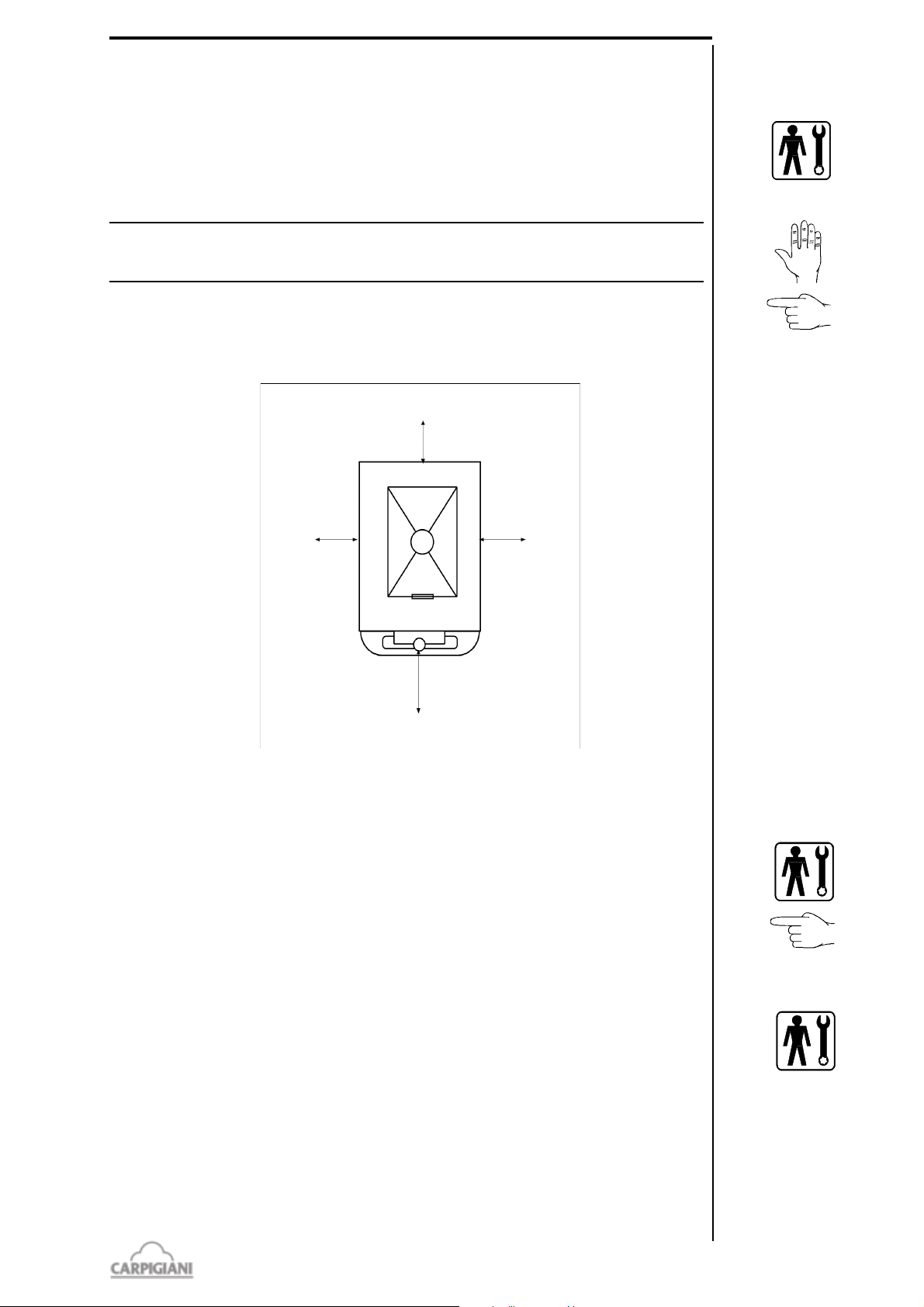
The machine must be installed in such a way that air can freely circulate allaround.
Rooms for the approach to the machine must be left free in order to enable the operator to act
without constraint and also to immediately leave working area, if need be.
The minimum approach room to working area should be at least 40 in.
ATTENTION
Machines with aircooled condenser must be installed no closer than 2 in to any wall in
order to allow free air circulation around the condenser.
NOTE
An insufficient air circulation affects operation and output capacity of the machine.
2 in
191 BAR USA
2 in
40 in
2 in
2.2 MACHINE WITH AIRCOOLED CONDENSER
Machines with aircooled condenser must be installed no closer than 2 in to any wall in order to allow
free air circulation around the condenser.
NOTE
An insufficient air circulation affects operation and output capacity of the machine.
2.3 MACHINES WITH WATERCOOLED CONDENSER
To make the machine run, a watercooled machine must be connected to running water supply, or
to a cooling tower.
Water must have a pressure of 1 Bar at least and a delivery at least equal to the estimated hourly
consumption.
Connect inlet pipe marked by plate "Water Inlet" to water supply installing a shut-off valve, and
outlet pipe marked by plate "Water Outlet" to a drain pipe, installing a shut-off valve.
13
191 bar usa_G - 09/02 - ed. 4
Page 14
191 BAR USA
2.3.1 Water valve adjustment
WARNING
If water valve must be retarded, this operation will have to be carried out by skilled personnel, only.
Valve adjustment must be carried out in such a way that no water flows when machine is off and
lukewarm water flows when machine is on.
NOTE:
Water consumption increases if temperature of entering water is above 68°F.
ATTENTION:
Do not leave the machine in a room with temperature below 32°F
without first draining water from the condenser.
2.4 ELECTRIC CONNECTION
Before connecting the machine to the mains, check that machine voltage indicated in data plate
corresponds with the mains (see sec. 1.1.1 point C).
Insert a differential magnetothermal protection switch adequately sized to absorption capacity
required (see sec. 1.1.1 point D) and with contact opening of 3 mm at least.
WARNING
Yellow/green ground wire must be connected to a good ground outlet.
Rotation direction by three-phased machines
The beater rotates anticlockwise. By gravity-feed machines, it is necessary to remove the plate and
check the direction of rotation.
Reversing rotation direction
To reverse the direction rotation, when wrong, it is necessay to interchange two of the three leads
coming from the circuit breaker.
2.4.1 Replacement of power supply cord
If the machine main cable is damaged, it must be replaced through a cable with similar features.
Replacement will have to be carried out by skilled technicians only.
2.5 LOCATION
Level the machine on the counter surface to ensure smooth operation and prevent mix from leaking.
2.6 REFILLING
Motor installed in the machine is of the type with lubrication for life; no action of checking/
replacing or topping up is necessary.
Gas filling necessary to the freezing system is carried out at CARPIGIANI works during machine
postproduction testing .
If a gas addition happens to be made, this must be carried out by skilled technicans, only, who can
also find out trouble origin.
191 bar usa_G - 09/02 - ed. 4
2.7 MACHINE TESTING
A postproduction test of the machine is carried out at Carpigiani premises; Operation and output
functionality of the machine are thoroughly tested.
Machine test at end user's must be carried out by skilled technicians or by one of CARPIGIANI
engineers.
After the machine positioning and correct connections, also carry out all operations necessary to
functional check and test of the machine.
14
Page 15
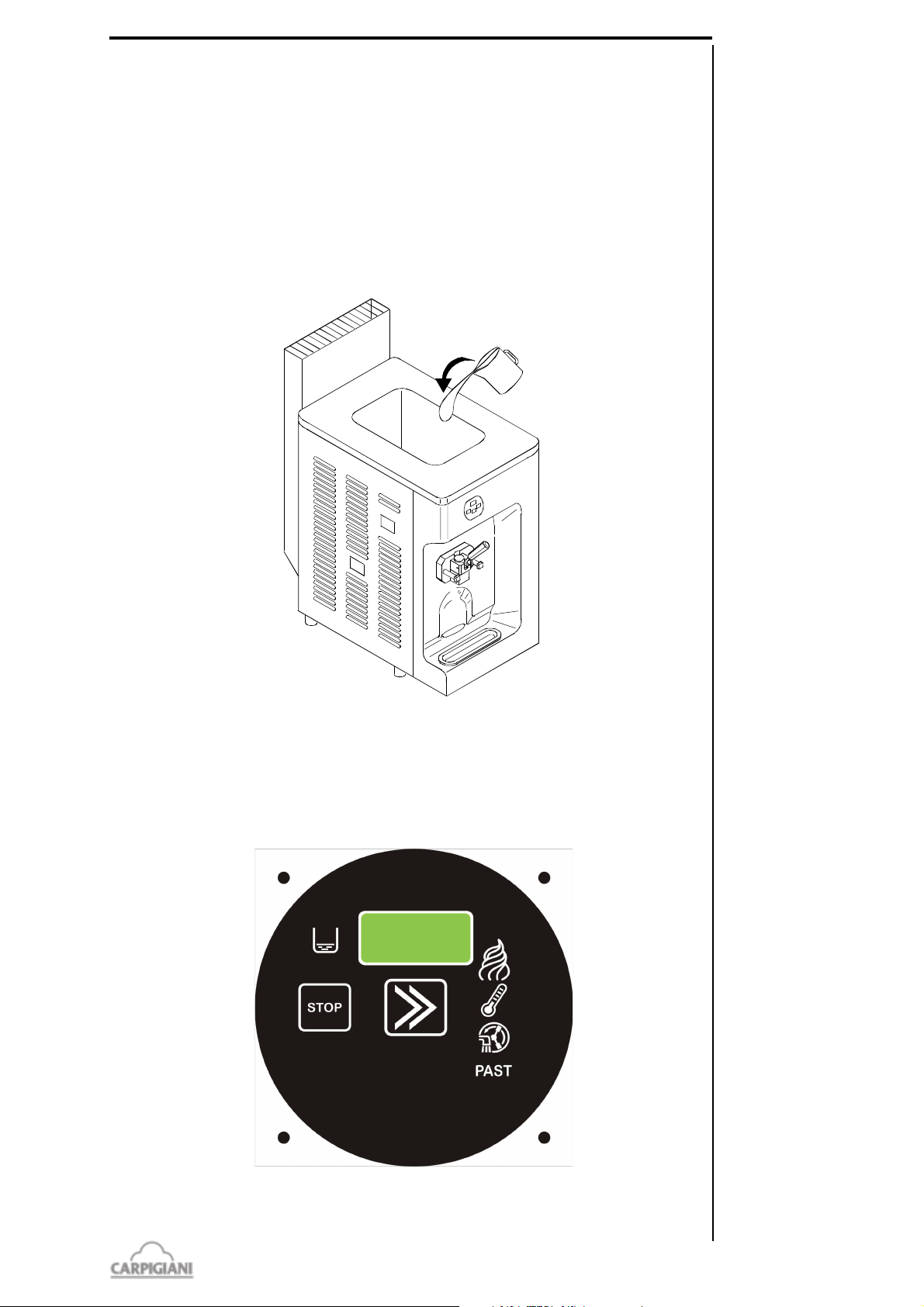
3. DIRECTION FOR USE
3.1 MACHINE CONFIGURATION
The machine is made up of a motor-drive to power the beater unit, and a cooling system with water
or air condenser.
Soft ice cream is prepared by filling the tank with cold mix (39°F) and starting the automatic
production cycle, until the ideal ice cream consistency set by CARPIGIANI is reached. Thanks
to the pump or feeding needle, the mix enters the beating cylinder already mixed with air; ice cream
is produced only when it needs to be served. The distributor valve on the machine front allows a
single portion of soft ice cream to be distributed. At the same time, the same amount of mix moves
from the upper cooled tub into the beating cylinder.
191 BAR USA
3.2 ELECTRONIC CONTROL KEYBOARD AND BUTTON
FUNCTIONS
Details of the panel are shown in the picture below.
15
191 bar usa_G - 09/02 - ed. 4
Page 16
191 BAR USA
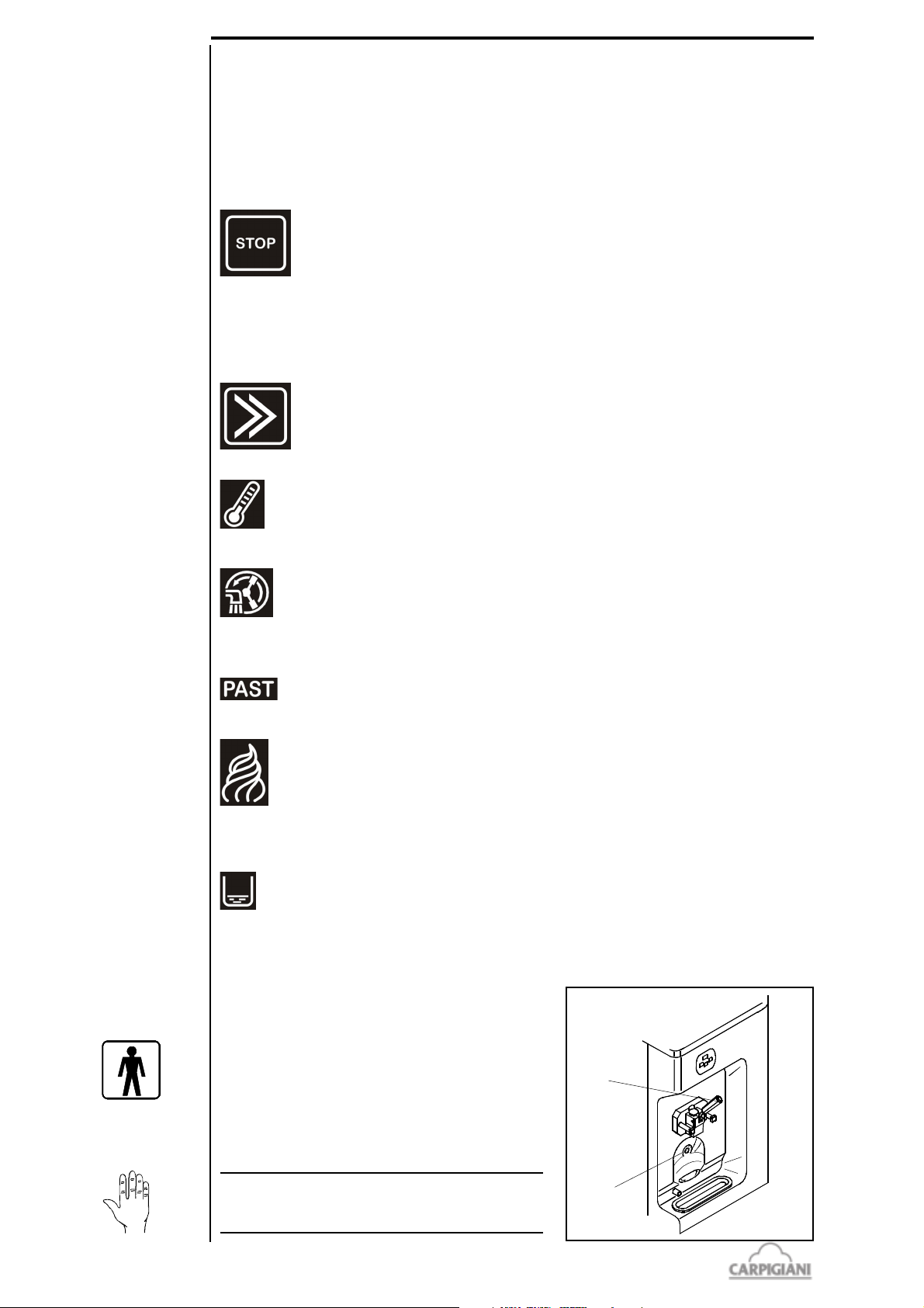
Lighted function indicators
The indicator lights up to show that the function corresponding to the symbol next to the indicator
itself is inserted.
Monitor
This display indicates the product consistency or product temperature in tank when the machine is
turned on and during its operation, while in DISTRIBUTION.
.
STOP button
STOP function selected and light indicator on: the machine is ready to receive all
the functions and the display shows the tank temperature. If, from any function,
we press STOP, the display will show OFF 2 seconds and it will then return to
the previous indication of tank temperature.
From Production and Storage it is necessary to press Stop 2 seconds, in order to
have the machine in STOP and so avoid “ touch” problems with the touchsensitive panel.
Function selection button
By pushing this button you may select any of the following functions:
Prd, Sto, CLE. The last selection made will be activated 2 seconds later.
STORAGE function (Sto)
When selecting this function, led lights up and the machine stores the mix both
in hopper and cylinder at a pre-set temperature of 39°F. The display indicates mix
temperature in the hopper.
CLEANING function (CLE)
When selecting this function, led lights up, the beater and the mix pump run,
while the refrigeration unit is off. This function is timed and ends automatically
when the set time (usually 30 seconds) is reached. The display indicates product
temperature in the cylinder.
Not available function.
PRODUCTION function (Prd)
When selecting this function the led lights up and the mix into the cylinder is
freezed until its set consistency (pre-set HOT setting) is reached. During this
cycle, the display indicates a number corresponding to the product consistency
in the cylinder till reaching of the preset value, then the same display will show
mix temperature in the hopper.
Tank level indicator
By lighting up, this led indicates that the mix level in the hopper has reached the
minimum allowed and refilling with fresh product is necessary. When the
indicator is on in PRODUCTION you can draw max. 10 cones out.
3.3 SPIGOT HANDLE
In order to dispense the product, place a cup or a cone
under the spout and slowly pull down the disepnsing
handle (pos. 5). As son as the product comes out, twist
the cup or the cone to form a cone-shaped serving.
When the portion has reached the desired size, close
the dispensing handle and quickly pull the cone or the
cup down in order to sharpen the tip.
5
191 bar usa_G - 09/02 - ed. 4
WARNING
It is important to keep the sensor (pos. 920)
clean
16
920
Page 17
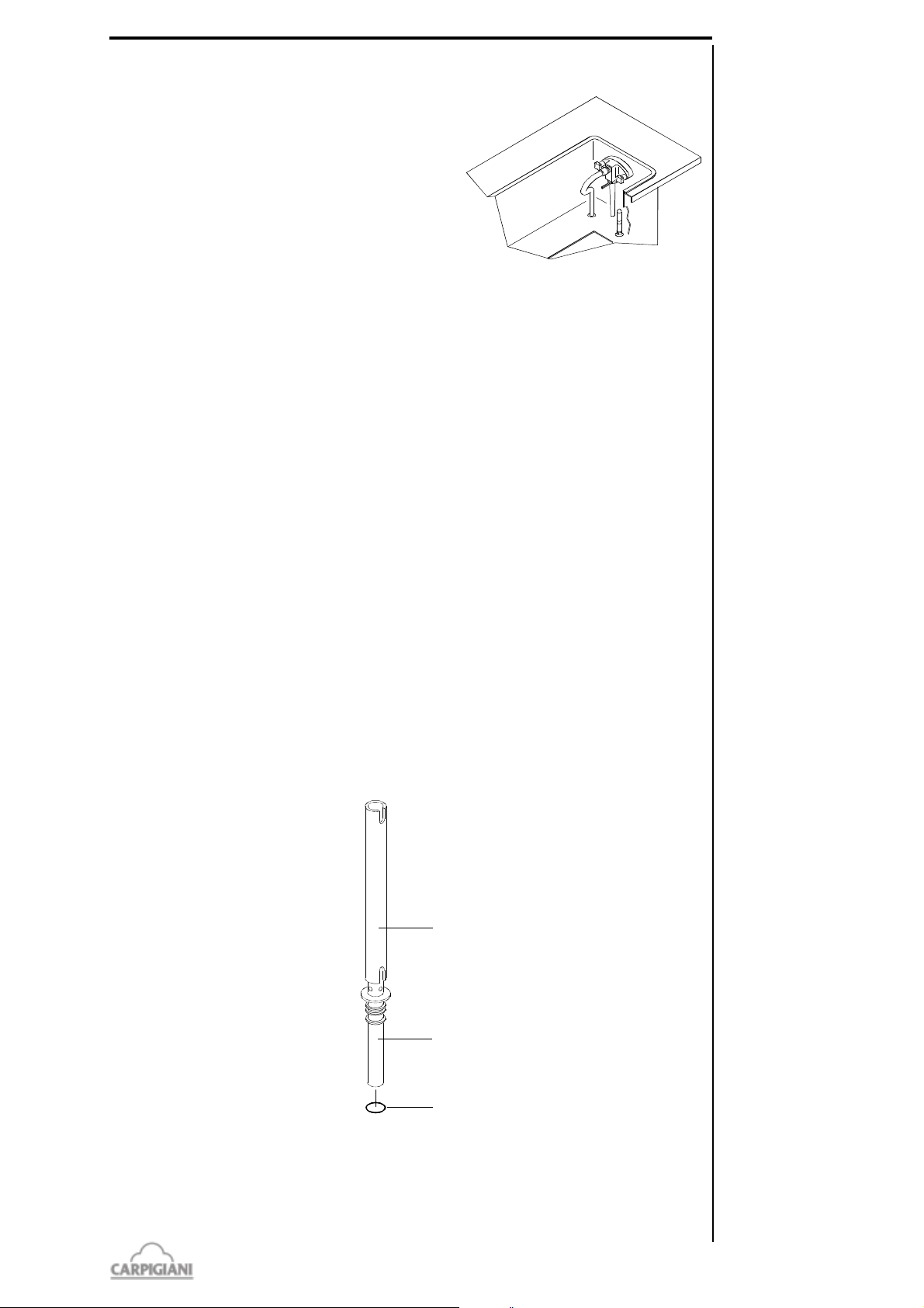
3.4 PUMP - FED MACHINES - "R" PUMP
52
53
1131
"R" pump allows, by changing position of regulator pos.
271, to vary proportions between air and mix conveyed to
the freezing cylinder; so, within certain limits, it allows
overrun regulation depending on mix used.
"R" pump regulator should be set to the middle position.
If, after dispensing a significant number of cones, ice
cream is too heavy and wet, you may move the R pump
regulator a notch at a time towards the right. If ice cream
comes out of spigot mixed with air bubles, then turn R
pump regulator a notch at a time towards the left.
3.5 GRAVITY - FEED MACHINE - FEEDING NEEDLE
How to obtein and how to keep quality performances.
1. Mantain a big mix level inside the hopper (above the half of the hopper itself). Mix temperature
inside the hopper is 39°F both during production and storage
2. During the day the mix must periodically be stirred by use of a plastic spatula to avoid
separation, particularly when product has not been dispensed over a long period and the
machine has been in "storage" mode for a long time.
3. A fluid mix without particles has to be used. A thick mix with big particles could close the slot
of the feeding neddle thus blocking mix from entering the cylinder.
4. Keep the feeding neddle slider (pos. 52) in a position as to allow for a smooth mix flow from
the hopper. By rotating the slider slot to the whole with smaller diameter, the quantity fo mix
to the tank will decrease, and vice versa.
5. Set the feeding needle in such a way that inlet hole is turned towards the middle of the tank.
6. Never exceed production limits in kilograms declared by Carpigiani, and dispense cones and
cups in the most regular way. If limits in production capacity as specified by Carpigiani are
exceeded the machine could stop. In this case appear on the display the alarm signal "ICE". If
this occours to reset the machine please operate as follow.
- stop the machine (pressing the push button to the STOP position)
- remove the feeding needle to enable a quick drop of the mix into the cylinder
- set machine in the "cleaning" position for a few minutes
- make sure that the product coming out for the spigot body when dispensing is liquid
- position the feeding needle again making sure the slider is sufficiently open
- start the machine putting it in the "production" mode. Do not start dipensing product
from the machine until the production cycle has been completed.
191 BAR USA
17
191 bar usa_G - 09/02 - ed. 4
Page 18
191 BAR USA
207
32
96
243
52
53
1131
3.6 PRELIMINARY OPERATIONS, WASHING AND
SANITIZATION
Before starting the machine for the first time, it is necessary to thoroughly clean its parts and
above all sanitize all parts coming into contact with the product.
WARNING
Machine provided with an automatic system for compulsory washing of the parts in
contact with food product.
Cleaning and sanitizing shall be executed as a habit (for example every 3 days) with care
in order to guarante quality of ice cream in full respect of necessary hygienic rules.
3.6.1 Cleaning
Lift tank cover and from its inside take out bag containing accessories, instruction booklet and
warranty sheet.
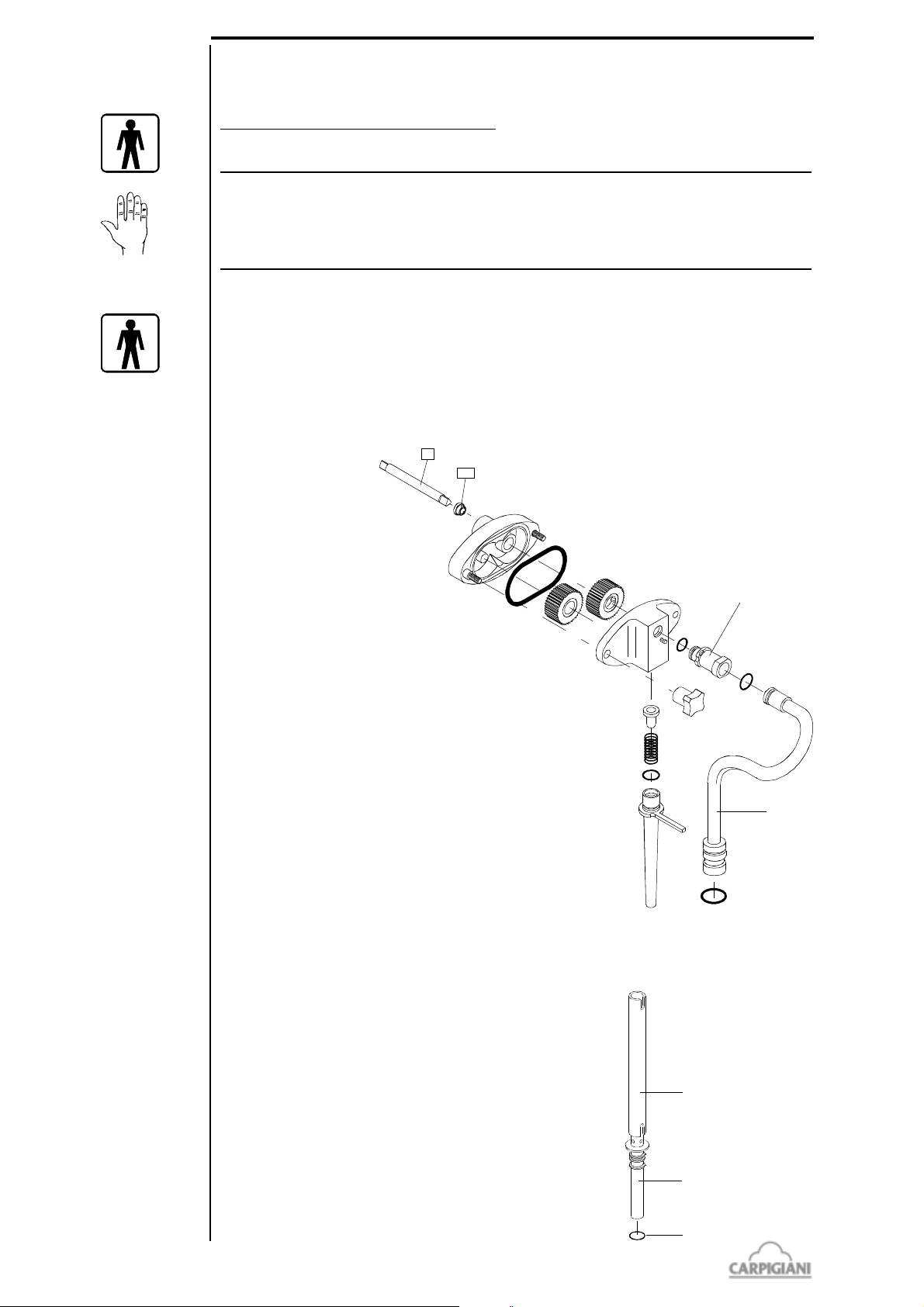
Remove the tank cover and the drip troughs.
By pump-fed machines:
- Disconnect the connection pipe (pos. 207) by turning it to match with the hole and free it from
the pin found on the
pump cover.
- Pull the connection
pipe backwards and
remove the feeding
pipe (pos. 32) by
turning it 90° then
pulling upwards.
- Removing the pump by
turning it clockwise of
45° then pull
backwards.
- Disassemble the pump
(see section 5 of this
manual).
191 bar usa_G - 09/02 - ed. 4
By gravity-fed machines:
- Extract the feeding needle slider (pos. 52), withdraw the slider from the tank bottom and
remove the OR (pos. 1131).
18
Page 19
Removing the door
1188
1153
8A
6
5
30
1285
28
21
28
21
24
25P
430
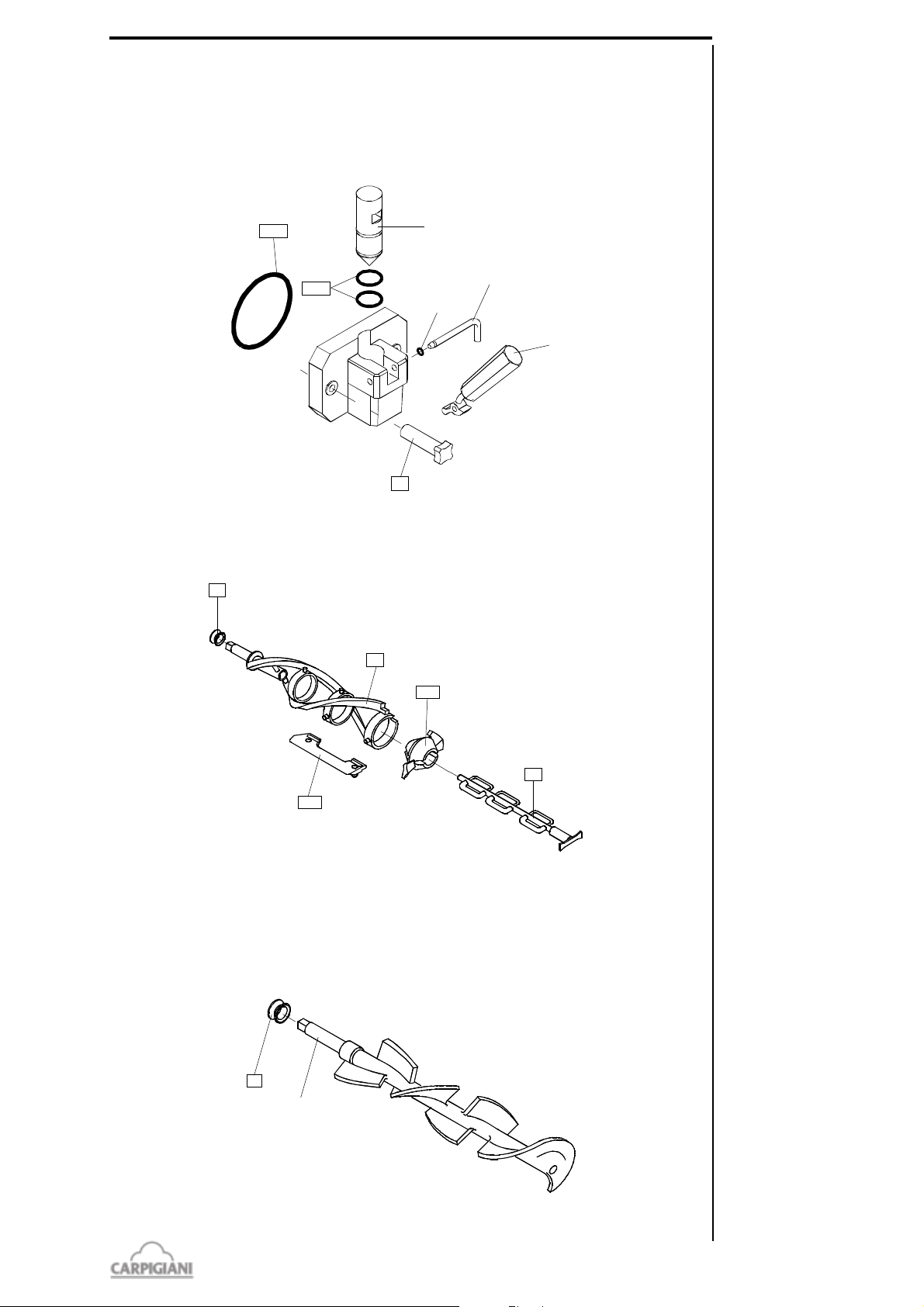
Remove the two retaining knobs (pos. 8A) and pull the door assembly towards you sliding it off
the two front panel studs. Pull the dispensing handle (pos. 5) so the piston (pos. 30) raises in its
housing. Remove the pivot pin O-ring (pos. 1285) and pull the pivot pin (pos. 6) out releasing the
dispensing handle (pos. 5). Using the dispensing handle lever pull the piston (pos. 30) out
completely. Using the o-ring extractor, remove the two piston o-rings (pos. 1153), and the large
dispensing door o-ring (pos. 1188).
191 BAR USA
By pump-fed machine: Removing the beater
Pull the beater out of the cylinder. Slide the beater seal (pos. 28) out of the beater shaft. Pull out and
remove the end pusher (pos. 25P) and the idler (pos. 24). Remove the 3 beater blades (pos. 430).
By gravity-fed machine: Removing the beater
Pull the beater out of the cylinder. Slide the beater seal (pos. 28) out of the beater shaft.
19
191 bar usa_G - 09/02 - ed. 4
Page 20
191 BAR USA
1- Fill a clean sink with detergent and hot water (122-140°F).
2- Wash the disassembled parts with the solution and scrub them thoroughly with the brushes
provided with the machine. As you proceed, rinse with hot water. Make sure all lubricant and
mix film is removed from parts.
3- Fill another sink with sanitizer prepared in 70-90°F water (ex. 1 packet in 2,5 gal. of water).
4- Place the parts in the sanitizing solution. Leave them there for a minimum of 1 minute (using
the sanitizing solution, the sanitizer manufacturers' directions are to be followed).
5- Place the components on a clean tray to air-dry.
6- Return to the machine with a small amount of sanitizer.
7- Dip a brush into the sanitizer and thoroughly brush the freezing cylinder
8- Dip the brush (pos. 772D) into the sanitizer solution and thoroughly brush the drip pipe.
9- Dip a brush into the sanitizer and thoroughly brush clean the mix inlet hole and the pump drive
hub opening in the rear mix hopper.
10-Spray the back of cylinder and the hopper walls with sanitizer.
Repeat step 7, 8, 9 and 10 several times
Reassemble and place the compression tube (see section 5 of this manual) into the tank and connect
to the pump only when cleaning operations are complete.
Reassemble the pump (see section 5 of this manual), making sure to use food-grade lubricant on
all o-ring and insert it in the hopper
Reassemsble the beater (see section 5 of this manual), insert it completly into the freezing cylinder
by grasping it with both hands.
WARNING
Insert the beater minding not to hit it against the cylinder wall, since you might scratch it
and so jeopardize the correct machine operation.
Reassemble the front lid (see section 5 of this manual) and install it back.
Reassemble and install the feeding needle (by gravity-feed machines)
Place the cover and the drip troughs back.
3.6.2 Sanitizing
CAUTION
For the use of sanitizers, instructions on labels are to be followed.
The machine must be sanitized before mix is poured in. Procede as follows:
1- Fill the hopper to the maximum level with sanitizer prepared in 70-90°F water (ex. 1 packet in
2,5 gal. of water) and allow to drain into the cylinder.
2- Using the brush, clean the mix level probes, the entire surface of the mix hopper, the surface of
the mix pump and the outside of the hopper agitator.
3- Select CLENOUT function and let the beater run for about 10 seconds. Press the STOP button.
The cylinder and the pump are now filled with the sanitizing solution.
4- Return to the machine with a small amount of sanitizer solution in a pail.
5- Dip the door spout brush in the pail of sanitizer and brush clean the dispensing spout. Repeat
the operation 2 times.
6- Wiper the exterior of machine with clean sanitized towel. Repeat the operation 2 times.
7- Wait for at least 5 minutes before proceeding with the next instructions.
8- Place an empty pail under the draw spout and pull the handle
9- Allow all of the sanitizier to drain. If the sanitizing solution does not flow out completely, keep
the spigot open and select CLENOUT function, keep the beater runnig for 5 seconds so that the
last solution residues flow out then push STOP.
191 bar usa_G - 09/02 - ed. 4
CAUTION
Do not keep the beater running for more than the time strictly needed to complete
washing and sanitization. Without the lubrification of mix butterfatu the beater wear
out quickly
3.6.3 Hygiene
Mildew and bacteria grow rapidly in the ice cream fat contents. To eliminate them, it is necessary
to thoroughly wash and clean all parts in contact with mix and ice cream, as described above.
Staineless steel and plastic materials, as well as rubber used in the construction and also their
particular shapes make cleanout easy, but cannot prevent proliferation of mildew and bacteria if
not properly cleaned.
20
Page 21
3.7 STARTING THE MACHINE
After installing the machine according to the instructions contained in the chapter INSTALLATION,
and after carefully cleaning and sanitizing the machine, proceed as follows:
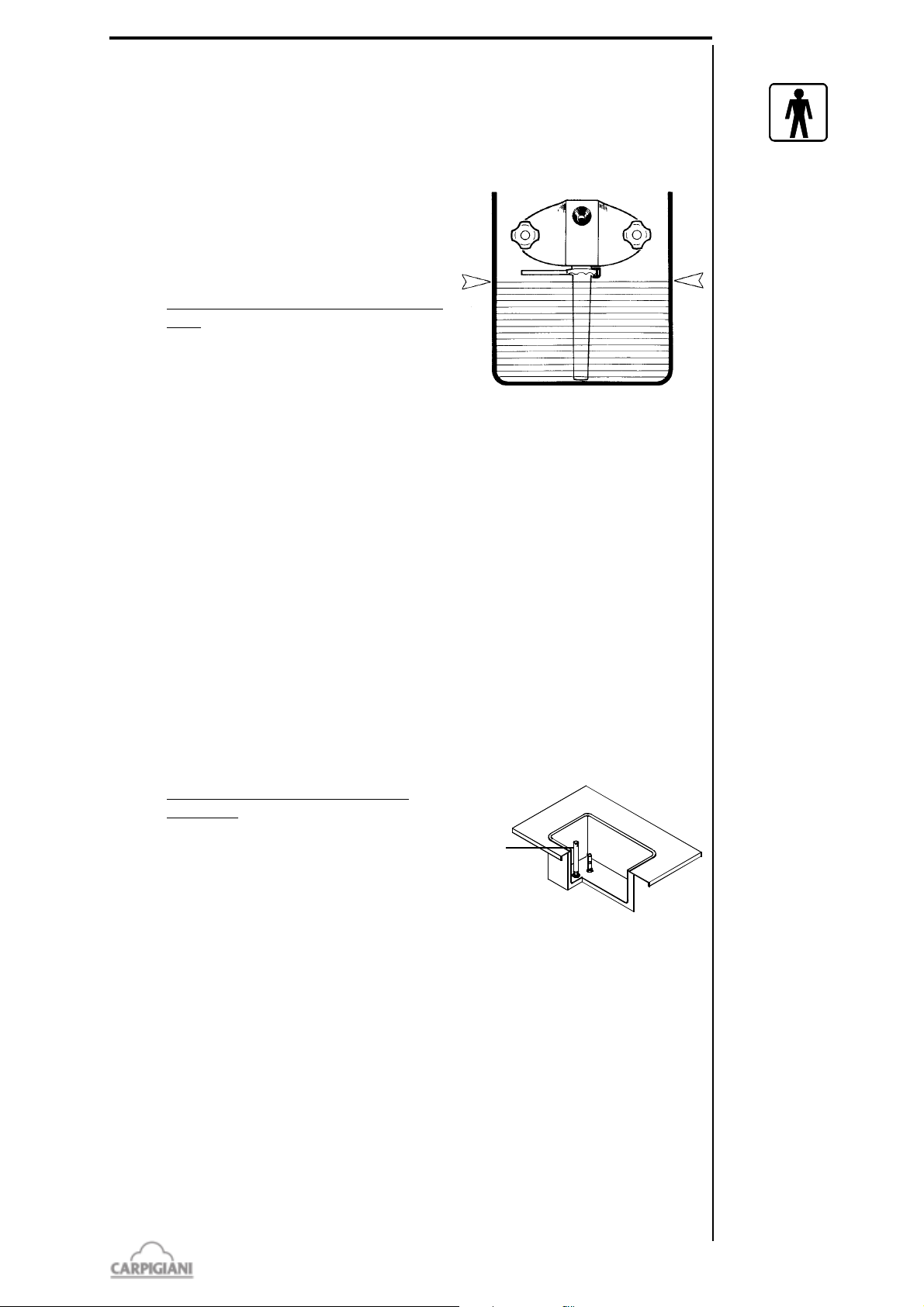
3.7.1 Starting machines with pump
Remove the compression pipe from bottom of the tank
and place it in the sanitizing solution.
Prime Hopper:
• Retrieve 1 bag of mix from the walk-in
refrigerator.
NB.: Mix to be poured at a temperature of 3941°F.
• With the draw handle open, pour one bag of
mix into the hopper allowing it to drain into
the freezing cylinder. Mix level in the tank
must never reach the pump (see picture) and
more mix must be added when level goes below about 2 cm from tank bottom.
• When only full strength mix (not mix and sanitizer) is flowing from the draw spout, close
the draw handle.
191 BAR USA
Connect the mix pressure pipe:
• When the mix stops bubbling from the bottom of the hopper, take the mix pressure pipe
from the sanitizing solution and insert it in its position in the bottom of the hopper. Make
sure your hands are clean and sanitized.
• Turn the pressure pipe clockwise towards the pump and connect the tube to the pump.
• Select production function to start the Automatic freezing operation.
• Replace the hopper cover.
3.7.2 Starting gravity-fed machines
Remove the feeding needle from tank bottom and place it in the sanitizer solution.
Prime Hopper:
• Retrieve 1 bag of mix from the walk-in
refrigerator.
NB.: Mix to be poured at a temperature
of 39-41°F.
• With the draw handle open, pour one
bag of mix into the hopper allowing it to
drain into the freezing cylinder. Mix
level in the tank must never exceed
feeding needle height (see picture) and
more mix must be added when level goes
below about 2 cm from tank bottom.
• When only full strength mix (not mix and sanitizer) is flowing from the draw spout, close
the draw handle.
feeding needle
Connect the feeding needle:
• When the mix stops bubbling from the bottom of the hopper, take the mix feeding needle
from the sanitizing solution and insert it in its position in the bottom of the hopper. Make
sure your hands are clean and sanitized.
• Select production function to start the Automatic freezing operation.
• Replace the hopper cover.
21
191 bar usa_G - 09/02 - ed. 4
Page 22
191 BAR USA
3.8 PRODUCTION
Dispense icecream without exceeding the machine production rate as shown in the table on page
13. If you do not exceed it, and provide to refill the machine with fresh mix, you can be sure you
will never have to stop selling, even during peak hours.
While your store is closed, set the machine to STORAGE by pushing SELECTION push-button
.
You will save significantly on energy consumption, as the compressor runs only for the time strictly
necessary in order to keep product at its correct temperature.
When you reopen the store, set the machine to DISTRIBUTION and within a few minutes
youghourt icecream will be back at the correct consistency for sale.
It is essential that you carry out CLEANING and SANITIZATION of the machine, daily or every
few days, depending on bacteriological quality of your mix as well as on health regulations in force
in your country.
If the machine has been stopped a long time due to a power failure, it is necessary that you check
product temperature before starting the sale again; if the temperature is over +43°F, the machine
must be emptied, cleaned and sanitized, and filled up with new fresh mix at +39°F.
3.9 OPEN PROCEDURE
3.9.1 Start the machine
Press the button to select PRODUCTION mode. The led light is on. Within a few minutes the
product is ready to be served.
3.10CLOSE PROCEDURE
3.10.1 Sanitize the door area
- Dip the door spout brush in a small amount of sanitizer solution and brush clean several
times the dispensing spout from the outside.
- Wash, rinse and sanitize the drip tray, the drip trough and the hopper cover.
- Wipe exterior of machine and the door area with clean sanitized towel.
3.11 ON THE DISPLAY
The CPU carries out a test on the keypanel and display, and all leds light for a functional test;
a “t” is thence displayed and soon followed by a number (for example 01) which indicates the
software version installed in the machine.
If the machine does not function, your technician will always have to specify this number (software
version), as well as the machine serial number to be found on data plate, so as to take the best
advantage of the After Sale Service.
Last, the writing “con” will be displayed and followed by the number of cones in 2 displays, at first
tens of thousands/thousands and then hundreds/tens/units (for example, 32.514).
During the routine operation the tank temperature (TEV) is displayed and during ice cream
production the product consistency is instead indicated on the display.
In cleaning mode, the cylinder temperature indicated by the sensor TEC is displayed.
191 bar usa_G - 09/02 - ed. 4
22
Page 23
3.12 PROGRAMMING FOR USER
In programming for the user, it is allowed to change the values pertinent to the ice cream
consistency.
In order to enter in Programming User instructions given below are to be followed:
1) Press the push-buttons Stop and Selection (from machine in Stop) at the same time and release
them when “000” is displayed. If no push-button is pressed within 5", the machine sets at Stop.
2) Press Selection and modify the value by incrementing it up to “012”.
Confirm with the push-button Stop.
3) Wait until Hot and its value (the latter can be changed between 40 and 120 with Selection) will
alternate on the display. Increasing this number will also increase ice cream hardness, as well
as and beater motor input.
4) To leave this mode, just wait for 30" or conceal the photocell (MIR).
191 BAR USA
23
191 bar usa_G - 09/02 - ed. 4
Page 24

191 BAR USA
191 bar usa_G - 09/02 - ed. 4
24
Page 25
4. SAFETY DEVICES
MRALA NOITPIRCSED
)CET(60A morfsemocgnippirtfI.)tiucrictrohsrednurodetpurrretni(ytluafrosnesrednilyC
morfdaetsnisemoctifI.potStateslliwenihcameht,egarotSronoitaziruetsaP
sknilbdeltnaveler:noitcnuftahtniniamerlliwenihcameht,noitcudorProgninaelC
.deyalpsideblliw60Adna
)VGT(70A lliwmralaehT.)tiucrictrohsrednurodetpurretni(ytluafrosnesrotaropaveknaT
emasehtnisniamersiht(enihcamehtpotstonlliwtubgniknilbdelkcehcesuac
.)noitcnuf
)SMI(90A .nepodiltnorF.hctiwstengamytefaS
)SSERP(11A eht,ylevitucesnoc’2spirttinehwrosemit3retfA.deppirthctiwserusserphgiH
.potStastesenihcam
)1ET(21A lliwmralaehT.)tiucrictrohsrednurodetpurretni(ytluafrosnesrotaropaverednilyC
emasehtnisniamersiht(enihcamehtpotstonlliwtubgniknilbdelkcehcesuac
.)noitcnuf
)TUOKCALB(51A ,gninaelCrofdetpecxe,sawtierehwnoitcnufehtotsnruterenihcamehT.tuokcalB
.elbaTtuokcalBehtotgnidroccagnilooCotsaPropotSotsnrutertierehw
)TLEB(02A VET=>semoceberutarepmetVGTfi,noitaziruetsaPfognitaeHnIVETVGTATLED
ehtdnadeyalpsidsi02A,VETVGTATLEDpetsnidemmargorpeulavehtotsa
.POTStakcabstesenihcam
)TUOEMIT(22A tuohtiw'51nahteromNOgniyatsfidnadellortnocsirotomretaebeht:noitcudorPnI
,daetsni,fI.22Amralahtiw,sutats”dehcaertoH“tastesenihcameht,TOHgnihcaer
.potStastesenihcameht,'51)kcolBTOH(BOHwolebsieulavycnetsisnoceht
)TUOXIM(42A aesnepsidewnoitcudorPnidna)noDELlevel(nosilevelmuminimehtnehW
,)senoCtsaL(32tpetsniteseulavehtnahtrehgihrosaemassnoitropforebmun
teserotredronipupoT.edomegarotStastesenihcamehtdnadeyalpsidsi42A
.mralaeht
btS teytonmaerceciroyBdnatSgninaem,BTSdeyalpsidebyamti,noitcudorpnI
.noitubirtsidrofydaer
MRALA NOITPIRCSED
)AMTP(10A deppirtnoitcetorplamrehT
)CMTP/CTR(20A deppirtnoitcetorplamrehtrosserpmoCroyalerlamrehtrosserpmoC
)VSET(30A deppirttatsomrehtytefaSknaT
)CSET(40A deppirttatsomrehtytefasrednilyC
)VET(50A gninaelCniretneylnonacuoY.)tiucrictrohsrednurodetpurretni(ytluafrosnesknaT
.potStaresenihcamehT.noitcnuf
4.1 ALARMS
The machine is provided with a self- “CHECK“ indicating possible troubles with your machine.
The “CHECK” led (the spot down on the right side of the display) blinks when an alarm is
active, and it stays on as a reminder of an alarm occurred and reset.
When an alarm is displayed, check which one through the table below.
The machine can be used in the distribution mode also when an alarm has occurred, provided
that it is non critical one; otherwise the machine will not allow to enter in the distribution
function; if this is the case, press STOP and do not use the machine till its repair.
Press Selection in order to delete the writing with reset alarm.
In the table below you can find list of available alarms:
191 BAR USA
Above 5 critical alarms cause machine to set at STOP, while led blinks if the alarm is still active
and is fixed on if reset.
25
191 bar usa_G - 09/02 - ed. 4
Page 26
191 BAR USA
MRALA NOITPIRCSED
SHP redronisesahp2trevniotyrassecensitI.potSnitfelsienihcaM.rellortnocesahP
.stesermralaeht,noenihcamehtgninrutnO.niagagninoitcnufstielbaneot
WOL tubsnoitcnufllanievitcasimralaehT.nosidelevreserdnatuosiximsknilb”WOL“
.gninaelC
4.1.1 Black-out
In case of a blackout, if the machine was:
- in Stop or Cleaning, on power return it sets at STOP.
- Production, or Storage: on power return, the machine sets back at the function where it was before
blackout and alarm A15 will be displayed.
191 bar usa_G - 09/02 - ed. 4
26
Page 27
5. DISASSEMBLING, WASHING, SANITIZING AND
REASSEMBLING THE PARTS IN CONTACT WITH
THE PRODUCT
Use a mild detergent to wash the parts.
Wash (by hands) the parts in water (at max 140°F), using a mild detergent ans the accessory
brushes. Use neither dish-washing machines, no detergents intended for them.
For rinse, use (bacteria free) drinking water. For sanitizing, leave the parts in sanitize lukewarm water
10 to 15 minutes (using the sanitizing solution, the sanitizer manufacturers' directions are to be
followed) and rinse before reassembling them.
5.1 PROGRAMMED CLEANING
The machine has been provided with an automatic system for compulsory washing of the parts
in contact with food product, for example every 3 days.
Such a system, called "WASH" inhibits the distribution function at the end of the 3rd day and
the message "WAS" will be displayed.
Every time you dispense ice cream or the beater motor starts, the number of days to next
programmed washing will be displayed.
WARNING
Cleaning and sanitizing shall be executed as a habit (for example every 3 days) with care in
order to guarante quality of ice cream in full respect of necessary hygienic rules.
191 BAR USA
5.1.1 Cleaning
Remove the tank cover and the drip troughs.
5.2 EMPTYING THE ICE CREAM PLANT
1 - Place a empty pail under the spout.
2 - Press the button.
3 - Pull the dispensing lever and drain the ice cream.
4 - Select CLENOUT function .
5 - When the product coming out becomes liquid, push STOP button and leave the spout open.
6 - Remove the hopper cover and the drip draws.
7 - For the pump fed machine: in the hopper, disconnect pressure pipe from the mix pump, turn it
sideways, remove it pulling it up from its seat and let the product flow completely out. Grasp the
pump an turn it in a clockwise direction of 45° then pull it out towards you.
8 - For the gravity fed macjhine: remove the feeding needle.
9 - Close the spout handle, pour 2,6 gal. of cool and clean water into the mix hopper. Use the white
hopper brush to scrub the mix hopper and mix level sensor. Use the small brush to clean the mix
inlet hole and the drive hub of the mix pump.
10- Place an empty pail under spout. Open the spigot piston and let the water drain out.
11- Rinse with warm water until the solution runs clear.
12- Select CLENOUT function .
13- Turn the machine off by pushing the button and let the water flow out.
14- Fill the hopper with 2,6 gal. of warm detergent solution.
15- Clean the hopper walls and the level sensor usign the supplied bushes.
16- Pull the dispensing handle and let the liquid flow out completely.
17- Rinse with clear water, pull the spigot handle and let the water flow out.
18- Fill the hopper with Sanitizer prepared in 70-90°F water (ex. 1 packet in 2,5 gal. of water). Use the
white hopper brush to scrub the mix hopper and mix level sensor. Use the small brush to clean
the mix inlet hole and the drive hub of the mix pump.
19- Select CLENOUT function and let the beater run for 10 seconds.
20- Push the STOP button. Let the Sanitizer solution stand for a minimum of 1 minute.
21- Pull the dispensing handle and let the water flow completely out.
27
191 bar usa_G - 09/02 - ed. 4
Page 28
191 BAR USA
207
32
96
243
52
53
1131
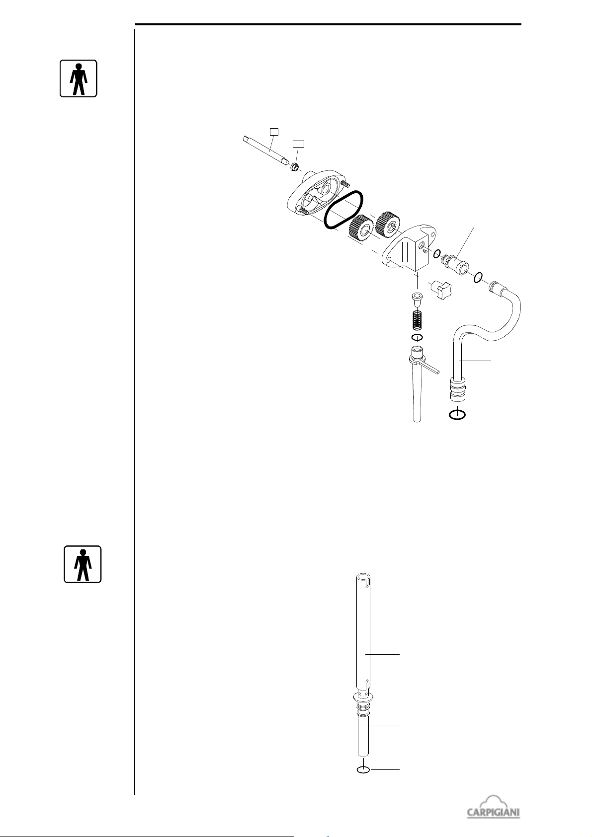
5.3 PUMP FED MACHINES - DISASSEMBLING MIX PUMP
1- Keeping the feeding tube (pos. 271) upward turn it counterclockwise and pull it out.
2- Pull the spring (pos. 206) and the back flow valve (pos. 245) out. Using the o-ring extractor,
remove the o-ring (1126).
3- Unscrew the 2 knobs (pos. 8) and separate the cover (pos. 202) from the pump body (pos. 39).
4. Tapping the pump body against the palm of your hand, remove the pump gears (pos. 38 and
38A). Using the oring extractor,
remove the large oring (pos. 1178).
5- Pull the connection
tube (pos. 207) from
the pressure pipe.
Remove the o-rings
(pos. 1117, 1126 and
1131).
5.4 GRAVITY FED MACHINES - DISASSEMBLING FEEDING
NEEDLE
To disassemble the feeding needle
- remove its slider (pos. 52)
- take the feeding needle out of the tank
- remove OR from the needle (pos. 1131)
191 bar usa_G - 09/02 - ed. 4
28
Page 29
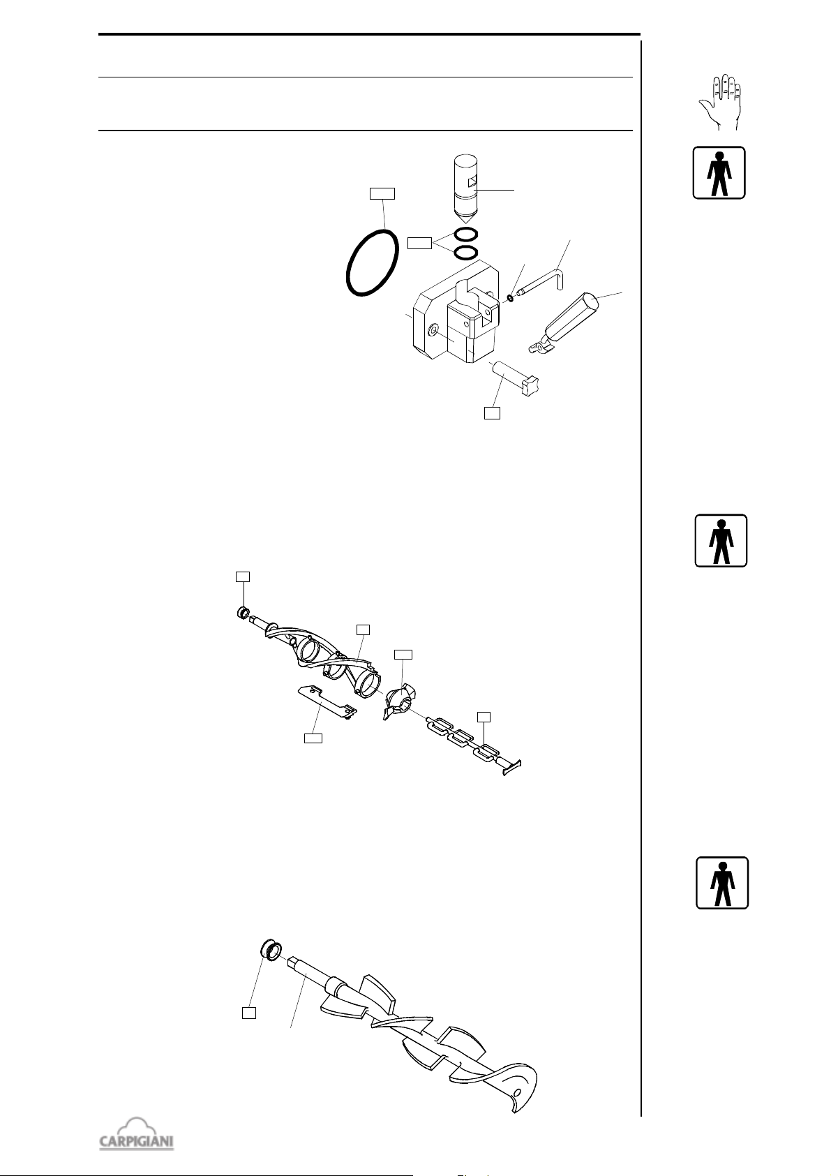
5.5 DISASSEMBLING OF THE DISPENSING DOOR
1188
1153
8A
6
5
30
1285
28
21
28
21
24
25P
430
CAUTION
Before disassembling the dispensing head, make sure that the hopper and the cylinder
are completely drained.
1- Remove the two retaining knobs (pos.
8A) and pull the door assembly towards
you sliding it off the two front panel
studs.
2- Pull the dispensing handle (pos. 5) so the
piston (pos. 30) raises in its housing.
3- Remove the pivot pin o-ring (pos. 1285)
and the pivot pin (pos. 6) out releasing
the dispensing handle (pos. 5)
4- Using the dispensing handle lever pull
the piston (pos. 30) out completely.
5- Using the o-ring extractor, remove the
two piston o-rings (pos. 1153), and the
large dispensing door o-ring (pos. 1188).
191 BAR USA
5.6 PUMP FED MACHINES - DISASSEMBLING BEATER
1- Pull the beater out of the cylinder.
2- Slide the beater seal (pos. 28) out of the beater shaft.
3- Pull out and remove the end pusher (pos. 25P) and the idler (pos. 24).
4- Remove the 3 beater blades (pos. 430).
5.7 GRAVITY FED MACHINE - DISASSEMBLING BEATER
1- Pull the beater out of the cylinder.
2- Slide the beater seal (pos. 28) out of the beater shaft.
3- Pull the idler (pos. 24) slightly to the front of the beater until the groove in the shaft of the idler
lines up with the slot on the beater frame. Pull the idler out.
29
191 bar usa_G - 09/02 - ed. 4
Page 30
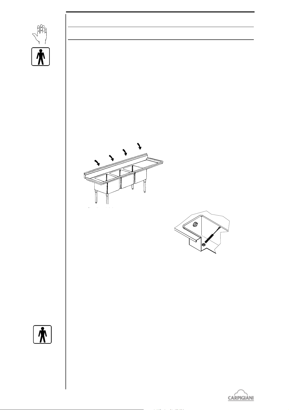
191 BAR USA
5.8 WASHING AND SANITIZING OF COMPONENT PARTS
CAUTION
For the use of sanitizers, instructions on labels are to be followed.
1- Fill a clean sink with detergent and hot water (122-140°F).
2- Wash the disassembled parts with the solution and scrub them thoroughly with the brushes
provided with the machine. As you proceed, rinse with hot water. Make sure all lubricant and
mix film is removed from parts.
3- Fill another sink with sanitizer prepared in 70-90°F water (ex. 1 packet in 2,5 gal. of water).
4- Place the parts in the sanitizing solution. Leave them there for a minimum of 1 minute.
5- Place the components on a clean tray to air-dry.
6- Return to the machine with a small amount of sanitizer.
7- Dip a brush into the sanitizer and thoroughly brush the freezing cylinder
8- Dip a brush into the sanitizer and thoroughly brush clean the mix inlet hole and the pump drive
hub opening in the rear mix hopper.
9- Spray the back of cylinder and the hopper walls with sanitizer.
Repeat step 7, 8 and 9 several times
4) Air-dry
3) Sanitize
2) Rinse
1) Wash
191 bar usa_G - 09/02 - ed. 4
5.9 PUMP FED MACHINES - REASSEMBLING MIX PUMP
1- Lubricate and replace the o-ring (pos. 1117) on the connection tube (pos. 207).
2- Lubricate and replace the o-rings (pos. 1126 and 1131) on the pressure pipe (pos. 32).
3- Insert the connection tube assembly in the pressure pipe (pos. 32)
4- Place the pressure pipe in a sanitizing solution.
5- Lubricate and replace the punp body o-ring (pos. 1178).
6- Lubricate the sides as well as the center of the pump gears (pos. 38 and 38A) with a thin film
of lubrificante insert them into the pump body (pos. 39). Do not lubricate the teeth of the
pump gears.
7- Lubricate and replace the o-ring (pos. 1412) on the feeding tube (pos. 271).
8- Hold the pump cover (pos. 202) upside down and insert the back flow valve (pos. 245) and
spring (pos. 206) in their pump cover housing.
30
Page 31
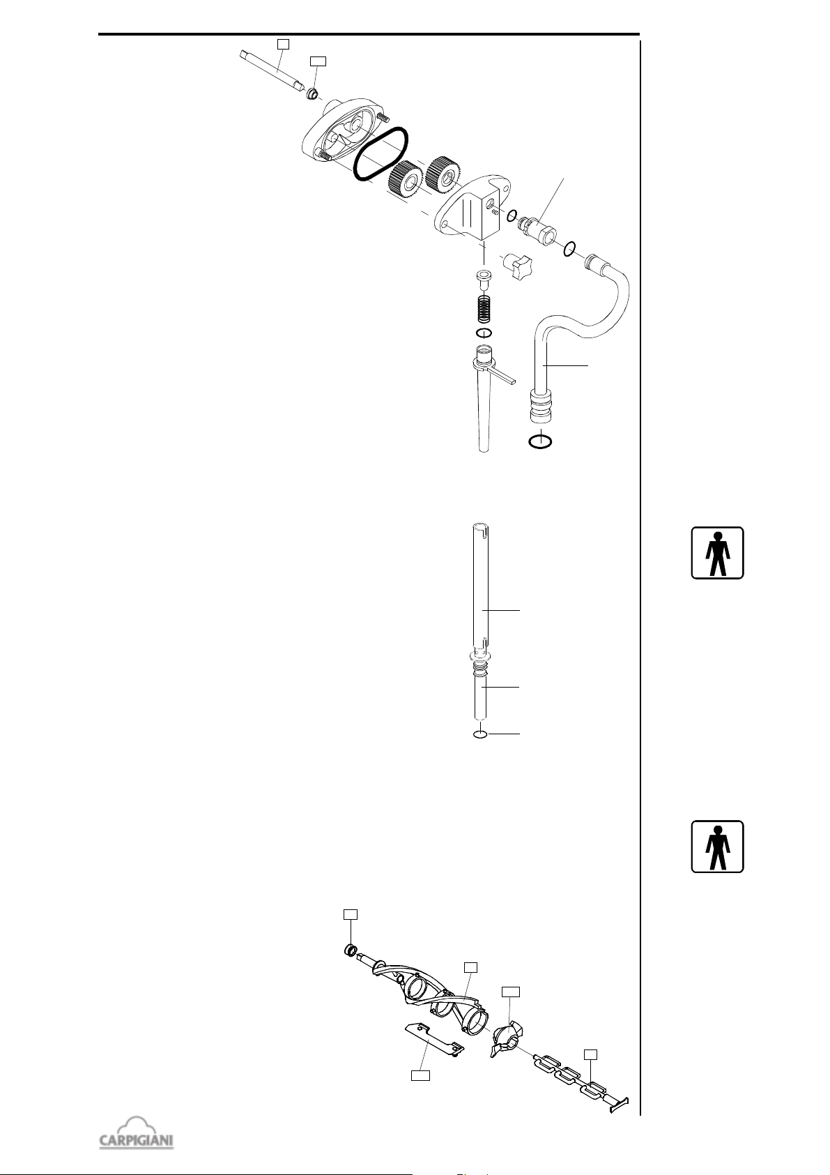
9- Insert the feeding
207
32
96
243
52
53
1131
28
21
24
25P
430
tube (pos. 271) in the
pump cover: push
and turn it clockwise.
10-Assemble the pump
cover (pos. 202) with
the feeding tube
downwards onto the
pump body and turn
the two knobs (pos.
8) tightly; install the
mix pump in the
hopper with the
blocking pin hook on
the right, turning the
pump counter
clockwise until it
locks onto the hopper
blocking pin.
191 BAR USA
5.10 GRAVITY FED MACHINES - REASSEMBLING FEEDING
NEEDLE
1- Lubricate the o-ring (pos. 1131)
2- Reasseemble the feeding needle
3- Place the feeding needle in the sanitizing solution.
5.11 PUMP FED MACHINES - REASSEMBLING BEATER
1- Insert the 3 beater blades (#430) onto the beater frame. Carpigiani suggests to replace the
blades each 6 months (please see the tune-up kit card).
2- Insert the end pusher (#25P) onto the beater frame.
3- Insert the end of the idler shaft (#24) in the rear housing of the beater, through the end pusher.
Push the idler into position.
4- Lubricate the sides of the beater seal
(#28) and slide it onto the beater shaft.
5- Insert the beater assembly into the
cylinder. Push it while turning it clockwise
until it engages in its rear hub, otherwise
the dispensing head cannot be fastened
properly, mix can flow out and serious
damage may occur.
31
191 bar usa_G - 09/02 - ed. 4
Page 32
191 BAR USA
1188
1153
8A
6
5
30
1285
7
28
21
5.12 GRAVITY FED MACHINES - REASSEMBLING BEATER
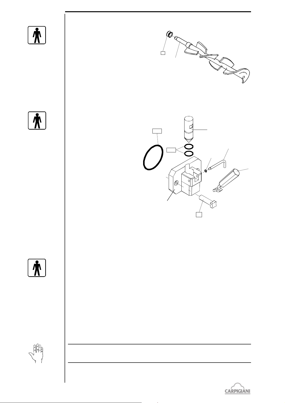
1- Lubricate the sides of the beater seal (pos.
28) and slide it onto the beater shaft.
2- Insert the beater assembly into the cylinder.
Push i while turning it clockwise until it
engages in its rear hub, otherwise the
dispensing head cannot be fastened properly,
mix can flow out and serious damage may
occur.
5.13 REASSEMBLING OF THE DISPENSING DOOR
1- Lubricate and slide the 2 piston o-ring (pos. 1153) into their seats.
2- Insert the piston (pos. 30), pointed end down, in the dispensing head (pos. 7) making sure that
the piston square notch lines up
with the rectangular opening on the
spigot front.
3- Position the dispensing handle
(pos. 5) on the door (pos. 7) and
insert the pivot pin (pos. 6) in its
housing through the handle lever
hole. Lubricate and insert the pivot
pin o-ring (pos. 1285). Lubricate and
slide into its seat the large
dispensing door o-ring (pos. 1188).
4- Insert the dispensing door assembly
onto the two front panel studs and
fasten it with the two knobs (pos.
8A) hand tight.
5.14 SANITIZING THE WHOLE MACHINE
The machine must be sanitized before mix is poured in. Procede as follows:
1- Fill the hopper to the maximum level with sanitizer prepared in 70-90°F water (ex. 1 packet in 2,5
gal. of water) and allow to drain into the cylinder.
2- Using the brush, clean the mix level probes, the entire surface of the mix hopper, the surface of
the mix pump.
3- Select CLENOUT function and let the beater run for about 10 seconds. Press the STOP button.
The cylinder and the pump are now filled with the sanitizing solution.
4- Return to the machine with a small amount of sanitizer solution in a pail.
5- Dip the door spout brush in the pail of sanitizer and brush clean the dispensing spout. Repeat
the operation 2 times.
6- Wiper the exterior of machine with clean sanitized towel. Repeat the operation 2 times.
7- Wait for at least 5 minutes before proceeding with the next instructions.
8- Place an empty pail under the draw spout and pull the handle
9- Allow all of the sanitizier to drain. If the sanitizing solution does not flow out completely, keep
the spigot open and select CLENOUT function, keep the beater runnig for 5 seconds so that the
last solution residues flow out then push STOP.
CAUTION
Do not keep the beater running for more than the time strictly needed to complete washing and
sanitization. Without the lubrification of mix butterfatu the beater wear out quickly
Place the cover and the drip troughs back.
191 bar usa_G - 09/02 - ed. 4
32
Page 33
5.15 MIX PRIMING
Prime Hopper:
• Retrieve 1 bag of mix from the walk-in refrigerator.
• With the draw handle open, pour one bag of mix into the hopper allowing it to drain into
the freezing cylinder.
• When only full strength mix (not mix and sanitizer) is flowing from the draw spout, close
the draw handle.
By pump fed machines - Connect the mix pressure pipe:
• When the mix stops bubbling from the bottom of the hopper, take the mix pressure pipe
from the sanitizing solution and insert it in its position in the bottom of the hopper. Make
sure your hands are clean and sanitized.
• Turn the pressure pipe clockwise towards the pump and connect the tube to the pump.
• Select production function to start the Automatic freezing operation.
• Replace the hopper cover.
By gravity fed machines - Connect feeding needle:
• When the mix stops bubbling from the bottom of the hopper, take the mix feeding needle
from the sanitizing solution and insert it in its position in the bottom of the hopper and
adjust the slider to the smallest diameter hole. Make sure your hands are clean and
sanitized.
• Select production function to start the Automatic freezing operation.
• Replace the hopper cover.
191 BAR USA
33
191 bar usa_G - 09/02 - ed. 4
Page 34

191 BAR USA
191 bar usa_G - 09/02 - ed. 4
34
Page 35
6. MAINTENANCE
28
21
24
25P
430
6.1 SERVICING TYPOLOGY
ATTENTION
Any servicing operation requiring the opening of machine panels must be carried out with
machine set to stop and disconnected from main switch!
Cleaning and lubricating moving parts is forbidden!
Repairs of electrical and freezing plants must be carried out by skilled engineers!
Operations necessary to proper machine running are such that most of servicing is completed during
production cycle.
Servicing operations, such as cleaning of parts in contact with the product, replacing of stuffing box,
disassembling of beater assembly are to be carried out at the end of a working day, so as to speed
up serving operations required.
Herebelow you can find a list of routine servicing operations:
- Cleanout and replacement of stuffing box
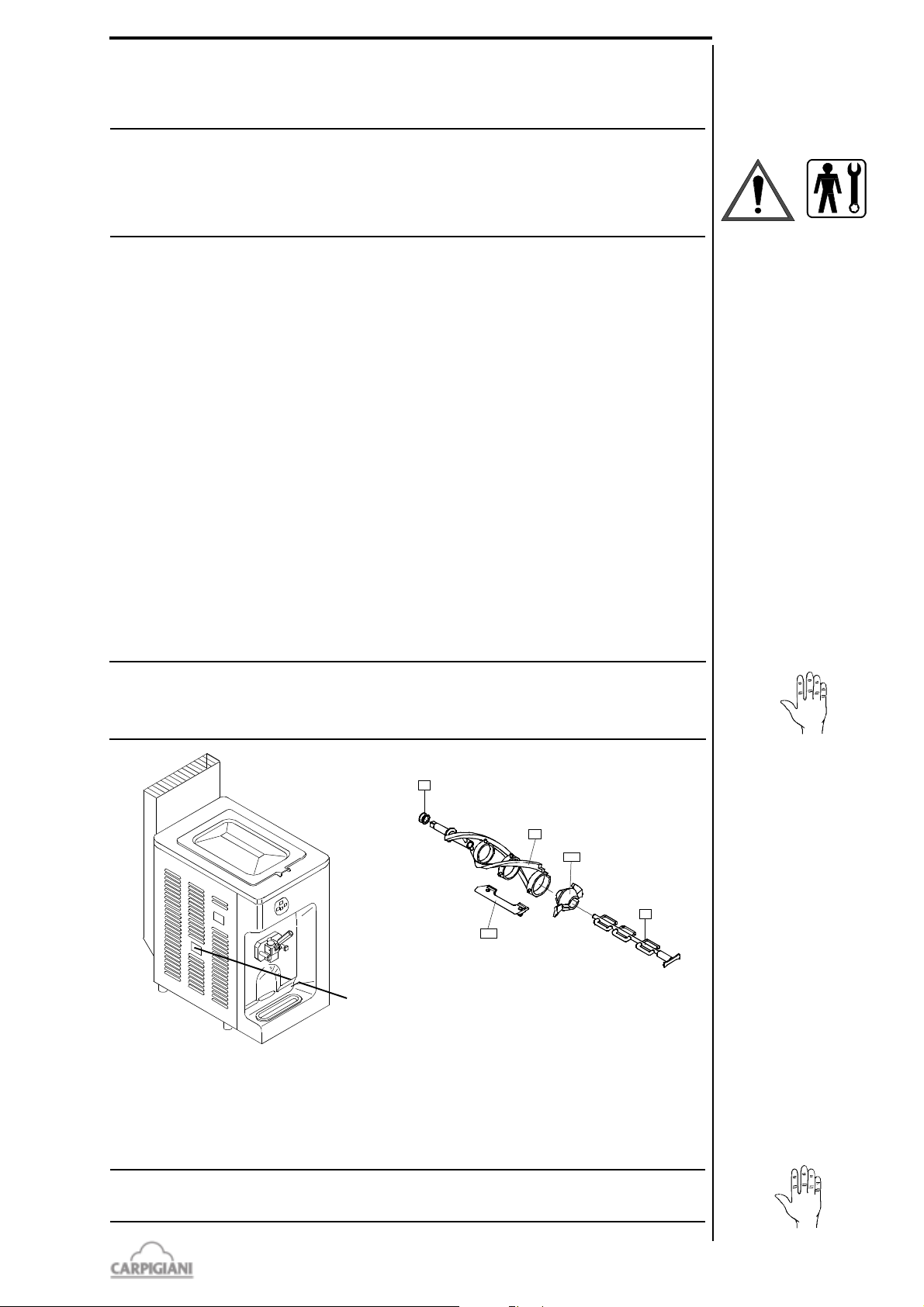
If the prodduct drips from the right drip pipe onto the machine front side, it means that the stuffing
box(pos. 28) has no tightness.
When dismantling the beater, check the status of the stuffing box; based on how long the machine
has been used, replace it if necessary, alternating it with the second stuffing box, provided with
the accessories packet included in the packing.
If the stuffing box has no defects, it can still be used after washing it, i.e., when at room
temperature, it has again its original shape.
To replace the stuffing box, proceed as follows.
Remove the beater unit
Remove the stuffing box from its slot
Lubricate the replacement stuffing box
Mount the new stuffing box
Clean and lubricate the replaced stuffing box and store it to allow it to regain flexibility.
191 BAR USA
WARNING
If you continue to work after noting traces of product in the drawer, you further accen-
tuate the leakage of the stuffing box; this can lead to a malfunction of the machine serious
enough to halt production.
drip
trough
- Cleanout of panels
To be carried out daily with neutral soap , seeing to it that cleansing solution never reaches beater
assembly at its inside.
- Cleanout of beater, pump or gravity feed, dispensing door and machine's sanitization
To be carried out according to procedures described in section 5 of this manual.
WARNING
Never use abrasive sponges to clean machine and its parts, as it might scratch their surfaces.
35
191 bar usa_G - 09/02 - ed. 4
Page 36
191 BAR USA
6.2 WATERCOOLING
By machines with watercooled condenser, water must be drained from condenser at the end of
selling season in order to avoid troubles in the event that the machine is stored in rooms where
temperature may fall under 32°F.
After closing water inlet pipe, withdraw drain pipe from its seat and let water flow out from circuit.
6.3 AIRCOOLING
Clean condenser, periodically, so as to remove dust, paper and what can prevent air from
circulating.
For cleanout, use a brush with long bristles or a bolt of compressed air.
ATTENTION!
When using compressed air, put on personal protections in order to avoid accidents; put
on protective glasses!
NEVER USE SHARP METAL OBJECTS TO CARRY OUT THIS OPERATION. GOOD
WORKING OF A FREEZING PLANT MOSTLY DEPENDS ON CLEANING OF
CONDENSER.
191 bar usa_G - 09/02 - ed. 4
36
Page 37
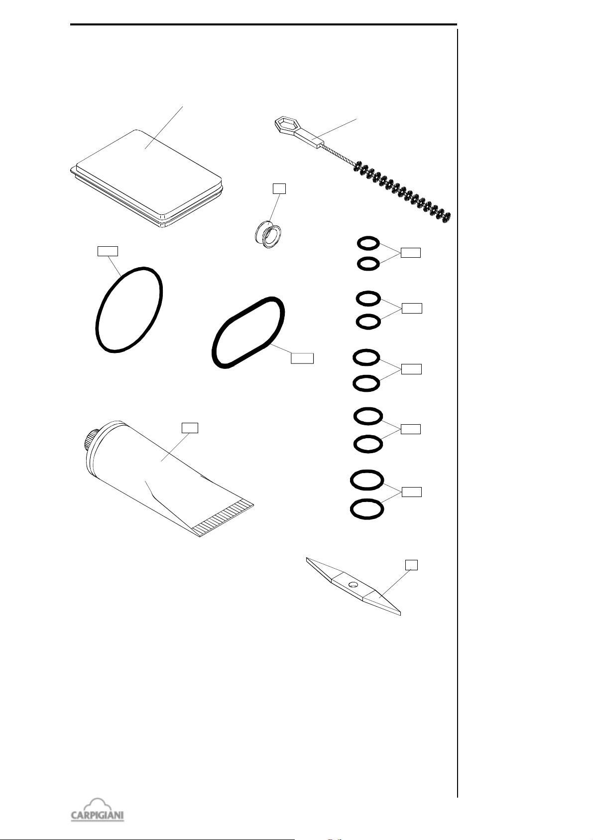
6.4 TABLE OF SPARE PARTS EQUIPMENT
1131
1153
830
1188
72
28
475
772C
772D
772A
772
1178
1117
1266
1126
772E
191 BAR USA
Pos. Description
28 Beater stuffing box
72 O ring extractor
475 Accessories
772 Brush D. 8x250
772A Brush D. 15x350
772C Brush D. 40x400
772D Brush D. 30x640
772E Brush D. 85x145x390
Pos. Description
830 food-grade lubrificant tube
1117 Gasket OR
1126 Gasket OR
1131 Gasket OR
1153 Gasket OR
1178 Gasket OR
1188 Gasket OR
1266 Gasket OR
37
191 bar usa_G - 09/02 - ed. 4
Page 38

191 BAR USA
191 bar usa_G - 09/02 - ed. 4
38
Page 39
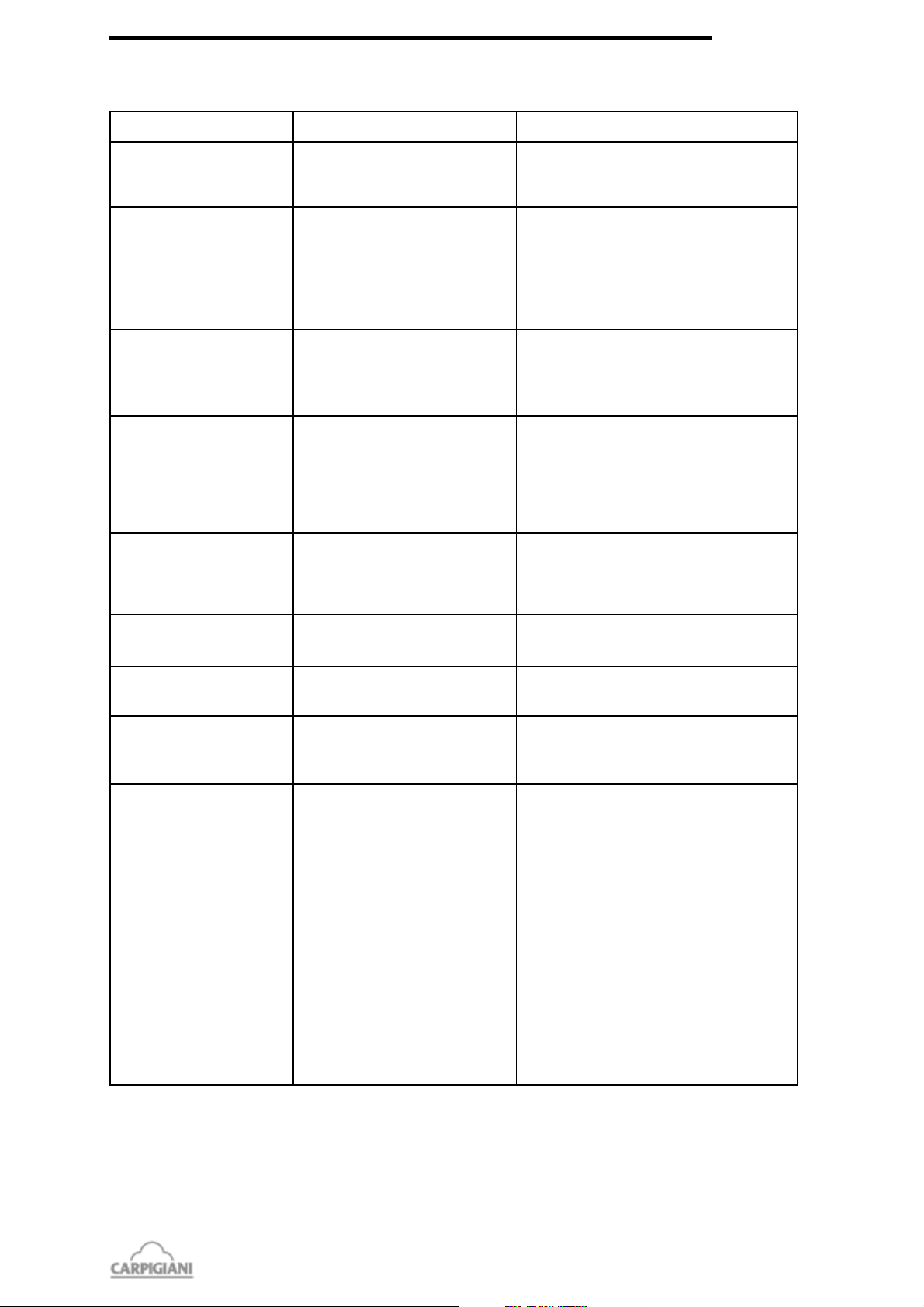
7 TROUBLESHOOT GUIDE
191 BAR USA
IRREGULARITY
Machine does not start.
Compressor starts and
then stops after a few
seconds.
Machine works but no ice
cream comes out of spigot.
Machine works but ice
cream is too soft
Mix or ice cream come out
above or below piston
though it is closed.
CAUSE
1.Burnt fuses.
2.Machine not properly plugged.
3.Alarm messages on display
1.If machine is watercooled:
water is not circulating.
2. If machine is aircooled: air is not
circulating.
1.Not enough sugar in mix.
2.Washing water has been left in
spigot and has frozen.
1.Too much sugar in mix.
2.Machine has run too long without
dispensing ice cream.
3.Ice cream is dispensed too fast.
1.Piston without OR or OR is wornout.
PROCEDURE TO FOLLOW
1.Check and replace.
2.Check and plug in. correctly.
3.See section 6,.
1.Open water inlet cock and check that pipe is
not squashed nor bent.
2.Check that machine rear side is at least 50 cm
from wall.
2.Clean condenser if obstructed by dust, or else.
1.Allow ice cream in barrel to thaw and then
modify or replace the mix.
2.Allow to thaw, take out a glass of ice cream
before
1.Modify or replace mix.
2.Take out ice cream until fresh mix reaches the
barrel.
3.Remember not to exceed production rate as
per table, and adjust ice cream dispensing
speed, if need be.
1.Insert or replace it with a new one if wornout.
Mix coming out of drip
drawer
Piston hard to operate.
Ice cream comes out from
front lid .
Bacteria tests show too high
level.
1.Stuffing box missing or worn-out.
1.Dry sugar on piston.
1.OR missing or not properly fit.
2.Front lid knobs not tightened
evenly.
1.Too many bacteria in the mix.
2.Machine not clean enough, nor
sanitized.
3.Mix left into the machine over 72
hours withouth performing cleaning
and sanitizing operations.
1.Install it if missing. If worn-out, replace it
with a new one.
1.Wash thoroughly and grease piston and OR
with edible fat.
1.Check and put remedy.
2.Stop machine. loosen and tighten them again.
1.Improve procedure of mix preparation by
sanitizing all containers. Have mix analyzed
before pouring it into the tank.
Storage temperature is too high: adjust storage
thermostat.
2.Empty and clean the machine with care. It is
then important to sanitize the machine as
indicated in section SANITIZATION.
3.Empty the machine: clean and sanitize it;
then fill with fresh and pasteurized mix kept at
39°F.
39
191 bar usa_G - 09/02 - ed. 4
 Loading...