


Service Manual
iR2030/2025/2022/2018 Series
Aug 8 2007


Application
This manual has been issued by Canon Inc. for qualified persons to learn technical theory, insta llati on, ma intenance, and repair
of products. This manual covers all localities where the products are sold. For this reason, there may be information in this
manual that does not apply to your locality.
Corrections
This manual may contain technical inaccuracies or typographical errors due to improvements or changes in products. When
changes occur in applicable products or in the contents of this manual, Canon will release technical information as the need
arises. In the event of major changes in the contents of this manual over a long or short period, Canon will issue a new edition
of this manual.
The following paragraph does not apply to any countries where such provisions are inconsistent with local law.
Trademarks
The product names and company names used in this manual are the registered trademarks of the individual companies.
Copyright
This manual is copyrighted with all rights reserved. Under the copyright laws, this manual may not be copied, reproduced or
translated into another language, in whole or in part, without the written consent of Canon Inc.
COPYRIGHT © 2001 CANON INC.
Printed in Japan
Caution
Use of this manual should be strictly supervised to avoid disclosure of confidential information.

Symbols Used
This documentation uses the following symbols to indicate special information:
Symbol Description
Indicates an item of a non-specific nature, possibly classified as Note, Caution, or Warning.
Indicates an item requiring care to avoid electric shocks.
Indicates an item requiring care to avoid combustion (fire).
Indicates an item prohibiting disassembly to avoid electric shocks or problems.
Indicates an item requiring disconnection of the power plug from the electric outlet.
Indicates an item intended to provide notes assisting the understanding of the topic in question.
Memo
Introduction
REF.
Indicates an item of reference assisting the understanding of the topic in question.
Provides a description of a service mode.
Provides a description of the nature of an error indication.

Introduction
The following rules apply throughout this Service Manual:
1. Each chapter contains sections explaining the purpose of specific functions and the relationship between electrical and mechanical systems with reference to the timing of operation.
In the diagrams, represents the path of mechanical drive; where a signal name accompanies the symbol , the arrow indicates the
direction of the electric signal.
The expression "turn on the power" means flipping on the power switch, closing the front door, and closing the delivery unit door, which results in
supplying the machine with power.
2. In the digital circuits, '1'is used to indicate that the voltage level of a given signal is "High", while '0' is used to indicate "Low".(The voltage value, however, differs from circuit to circuit.) In addition, the asterisk (*) as in "DRMD*" indicates that the DRMD signal goes on when '0'.
In practically all cases, the internal mechanisms of a microprocessor cannot be checked in the fi eld. Ther efore, the operations of the microprocessors
used in the machines are not discussed: they are explained in terms of fro m sensors to the input of the DC controller PCB and from the output of the
DC controller PCB to the loads.
The descriptions in this Service Manual are subject to change without notice for product improvement or other purposes, and major changes will be communicated in the form of Service Information bulletins.
All service persons are expected to have a good understanding of the contents of this Service Manual and all relevant Service Information bulletins and be
able to identify and isolate faults in the machine."


Contents
Contents
Chapter 1 Introduction
1.1 System Construction ..................................................................................................................................1- 1
1.1.1 Pickup/Delivery/Original Handling Accessories System Configuration (iR2018).....................................................1- 1
1.1.2 Pickup/Delivery/Original Handling Accessories System Configuration (iR2018i)....................................................1- 2
1.1.3 Pickup/ Delivery /Original Handling Accessories System Configuration (iR2022/iR2022N/iR2025/iR2030)...........1- 3
1.1.4 Pickup/Delivery/Original Handling Accessories System Configuration (iR2022i/iR2022K/iR2025i/iR2030i)...........1- 4
1.1.5 Reader Heater/Cassette Heater System Configuration (iR2018/iR2022/iR2022N) ................................................1- 5
1.1.6 Reader Heater/Cassette Heater System Configuration (iR2018i)...........................................................................1- 6
1.1.7 Reader Heater/Cassette Heater System Configuration (iR2022K/iR2022i/iR2025/iR2025i/iR2030/iR2030i) .........1- 7
1.1.8 Printing/Transmitting Accessories System Configuration (iR2018/ir2022/iR2022N)...............................................1- 8
1.1.9 Printing/Transmitting Accessories System Configuration (iR2018i/iR2022i/iR2022K/iR2025/iR2025i/iR2030/iR2030i)
1- 9
1.1.10 Functions of the Printing/Transmission Functions (iR2018/iR2022/iR2022N).....................................................1- 10
1.1.11 Functions of the Printing/Transmission Functions (iR2018i/iR2022i/iR2022K/iR2025/iR2025i/IR2030/iR2030i) 1- 10
1.2 Product Specifications..............................................................................................................................1- 10
1.2.1 Names of Parts.................................... .................................................. ................................................................1- 10
1.2.1.1 External View (iR2030i/iR2025i/iR2022i)............................................................................................................................... 1- 10
1.2.1.2 External View (iR2020/iR2020N/iR2030/iR2025) ..................................................................................................................1- 11
1.2.1.3 External View (iR2018i) .........................................................................................................................................................1- 11
1.2.1.4 External View (iR2018) .......................................................................................................................................................... 1- 12
1.2.1.5 Cross-Section ........................................................................................................................................................................ 1- 12
1.2.2 Using the Machine .................................................................................................................................................1- 13
1.2.2.1 Turning On the Power Switch (iR2018/iR2022/iR2022N)...................................................................................................... 1- 13
1.2.2.2 Turning On the Power Switch (iR2018i/iR2020i/iR2020K/iR2025/iR2025i/iR2030/iR2030i) ................................................. 1- 14
1.2.2.3 When Turning Off the Main Power Switch (iR2018/iR2022/iR2022N)...................................................................................1- 15
1.2.2.4 When Turning Off the Main Power Switch (iR2018i/iR2022i/iR2022K/iR2025/iR2025i/iR2030/iR2030i) .............................. 1- 16
1.2.2.5 Control Panel ......................................................................................................................................................................... 1- 17
1.2.3 User Mode Items...................................... ................................................... .. ........................................................1- 18
1.2.3.1 Common Settings (iR2030i/iR2030/iR2025i/iR2025/iR2022i/iR2018i) .................................................................................. 1- 18
1.2.3.2 Timer Settings (iR2030i/iR2030/iR2025i/iR2025/iR2022i/iR2018i)........................................................................................1- 19
1.2.3.3 Adjustment/Cleaning (iR2030i/iR2030/iR2025i/iR2025/iR2022i/iR2018i).............................................................................. 1- 19
1.2.3.4 Report Settings (iR2030i/iR2030/iR2025i/iR2025/iR2022i/iR2018i) ......................................................................................1- 19
1.2.3.5 System Settings (iR2030i/iR2030/iR2025i/iR2025/iR2022i/iR2018i).....................................................................................1- 20
1.2.3.6 Copy Settings (iR2030i/iR2030/iR2025i/iR2025/iR2022i/iR2018i)......................................................................................... 1- 21
1.2.3.7 Communication Settings (iR2030i/iR2030/iR2025i/iR2025/iR2022i/iR2018i)........................................................................1- 21
1.2.3.8 Printer Settings (iR2030i/iR2030/iR2025i/iR2025/iR2022i/iR2018i) ...................................................................................... 1- 22
1.2.3.9 Address Book Settings (iR2030i/iR2030/iR2025i/iR2025/iR2022i/iR2018i)........................................................................... 1- 23
1.2.3.10 Recommended setting of system management information................................................................................................ 1- 23
1.2.3.11 The Reference Information of the Department ID Management .......................................................................................... 1- 23
1.2.4 Maintenance by the User.......................................................................................................................................1- 23
1.2.4.1 User Maintenance Items........................................................................................................................................................ 1- 23
1.2.4.2 Cleaning (LCD type) .............................................................................................................................................................. 1- 24
1.2.4.3 Cleaning (Touch panel type).................................................................................................................................................. 1- 25
1.2.5 Safety ....................................................................................................................................................................1- 26
1.2.5.1 Safety of the Laser Light........................................................................................................................................................1- 26
1.2.5.2 CDRH Regulations................................................................................................................................................................. 1- 26
1.2.5.3 Handling the Laser Unit ........................................................................................................................................................ 1- 26
1.2.5.4 Handling the Laser Unit ......................................................................................................................................................... 1- 27
1.2.5.5 Safety of Toner ...................................................................................................................................................................... 1- 28
1.2.5.6 Point to Note about Fire.........................................................................................................................................................1- 28
1.2.5.7 Cautions as to the replacement and disposal of lithium battery............................................................................................. 1- 28
1.2.6 Product Specifications...........................................................................................................................................1- 29
1.2.6.1 Product Specifications ........................................................................................................................................................... 1- 29

Contents
1.2.7 Function List............................................................................... ... .........................................................................1- 30
1.2.7.1 Printing Speed (iR2030/iR2030i) ........................................................................................................................................... 1- 30
1.2.7.2 Printing Speed (iR2025/iR2025i) ........................................................................................................................................... 1- 31
1.2.7.3 Printing Speed (iR2022/iR2022i/iR2022K/iR2022N)) ............................................................................................................ 1- 32
1.2.7.4 Printing Speed (iR2018/iR2018i/iR2018N) ............................................................................................................................ 1- 34
1.2.7.5 Types of Paper....................................................................................................................................................................... 1- 35
Chapter 2 Installation
2.1 Making Pre-Checks....................................................................................................................................2- 1
2.1.1 Selecting the Site of Installation...............................................................................................................................2- 1
2.1.2 Before Starting the Work (230V CENV)...................................................................................................................2- 1
2.1.3 Before Starting the Work (230V CENV)...................................................................................................................2- 4
2.2 Unpacking and Installation .........................................................................................................................2- 6
2.2.1 Unpacking and Removing the Packaging Materials ................................................................................................2- 6
2.2.2 Unpacking and Removing the Packaging Materials ................................................................................................2- 6
2.2.3 Installing the Drum Unit............................................................................................................................ ................2- 6
2.2.4 Installing the Toner Bottle............................................................................................................... .........................2- 8
2.2.5 Installing the Toner Bottle............................................................................................................... .........................2- 9
2.2.6 Setting the Cassettes................................................... ... .......................................................................................2- 10
2.2.7 Attaching the Ferrite Core......................................................................................................................................2- 11
2.2.8 Checking the Image Quality. ..................................................................................................................................2- 11
2.2.9 Setting the Country/Region....................................................................................................................................2- 11
2.2.10 Setting the Country/Region..................................................................................................................................2- 11
2.2.11 Setting the Date and Time ...................................................................................................................................2- 12
2.2.12 Setting the Date and Time ...................................................................................................................................2- 13
2.2.13 Attaching Other Parts....................................................... ... .................................................................................2- 14
2.3 Checking the Connection to the Network.................................................................................................2- 15
2.3.1 Checking the Network Connection.........................................................................................................................2- 15
2.3.2 Checking the Network Connection.........................................................................................................................2- 16
2.4 Flow of Accessory Installation................. ... ... .... ... ... ... ....................................... ... ... .... ... ... .......................2- 17
2.4.1 Flow of Accessary Installation (230V CENV).........................................................................................................2- 17
2.4.2 Flow of Accessary Installation (230V CENV).........................................................................................................2- 18
2.5 Installing the Card Reader........................................................................................................................2- 19
2.5.1 Points to Note ........................................................................................................................................................2- 19
2.5.2 Checking the Contents................................... ........................................................................................................2- 19
2.5.3 Installation Procedure............................................................................................................................................2- 21
2.5.4 Registering the Card IDs................................... .....................................................................................................2- 26
2.5.5 Registering the Card IDs................................... .....................................................................................................2- 28
2.6 Installing the Heater PCB.........................................................................................................................2- 29
2.6.1 Preparing the parts ................................................................................................................................................2- 29
2.6.2 Preparing the Host Machine ..................................................................................................................................2- 29
2.6.3 Installing the Heater PCB.......................................................................................................................................2- 32
2.7 Installing the Reader Heater..................................................................................................................... 2- 35
2.7.1 Preparing the parts ................................................................................................................................................2- 35
2.7.2 Installing the Reader Heater Harness....................................................................................................................2- 36
2.7.3 Removing Reader Components.............................................................................................................................2- 41
2.7.4 Removing Parts at the Left of the Reader..............................................................................................................2- 41
2.7.5 Installing the Reader Heater..................................................................................................................................2- 43
2.8 Installing the Cassette Heater ..................................................................................................................2- 47
2.8.1 Preparing the parts ................................................................................................................................................2- 47
2.8.2 Installing the Cassette Heater................................................................................................................................2- 48
2.9 Installing the Control Card Cable .............................................................................................................2- 51
2.9.1 Preparing the parts ................................................................................................................................................2- 51
2.9.2 Installing the Control Card Cable...........................................................................................................................2- 52

Contents
Chapter 3 Main Controller
3.1 Construction ...............................................................................................................................................3- 1
3.1.1 Construction and Mechanisms......................................................................................................................... ... ....3- 1
3.2 Construction of the Electrical Circuitry........................................................................................................3- 1
3.2.1 Image Processor PCB....................................................... ... ...................................................................................3- 1
3.3 Image Processing.......................................................................................................................................3- 2
3.3.1 Overview of the Image Flow....................................................................................................................................3- 2
3.3.2 Construction of the Image Processing Module........................................................................................................3- 3
3.3.3 Reader Unit Input Image Processing.......................................................................................................................3- 3
3.3.4 Compressio/ Extesion/ Editing Block . ........................................................................................................ ... ..........3- 4
3.3.5 Printer unit Output Image Processing......................................................................................................................3- 4
3.4 Flow of Image Data ....................................................................................................................................3- 5
3.4.1 Flow of Image Data According to Copy Functions ..................................................................................................3- 5
3.4.2 Flow of Image Data for the SEND Function .................................................................................................. ..........3- 5
3.4.3 Flow of Image Data for the Fax Transmission.................................................................................................. ... ....3- 6
3.4.4 Flow of Image Data for the Fax Reception Function ........................................................................................... ... .3- 6
3.4.5 Flow of Image Data for the PDL Function .................................................................................................. ... ... .......3- 7
3.5 Parts Replacement Procedure ...................................................................................................................3- 8
3.5.1 Main Controller PCB........................................................................................................................... .....................3- 8
3.5.1.1 Preparation for Removing the Image Processor PCB ............................................................................................................. 3- 8
3.5.1.2 Removing the Image Processor PCB ...................................................................................................................................... 3- 8
3.5.1.3 Procedure after Replacing the Image Processor PCB........................................................................................................... 3- 10
3.5.2 SDRAM..................................................................................................................................................................3- 10
3.5.2.1 Preparation for Removing the SDRAM..................................................................................................................................3- 10
3.5.2.2 Removing the SDRAM...........................................................................................................................................................3- 11
Chapter 4 Original Exposure System
4.1 Construction ...............................................................................................................................................4- 1
4.1.1 Specifications, Control Methods, and Functions (iR2030i/iR2030/iR2025i/iR2025/iR2022i/iR2022) ......................4- 1
4.1.2 Specifications, Control Methods, and Functions (iR2018i/iR2018) .........................................................................4- 1
4.1.3 Major Components (iR2030i/iR2030/iR2025i/iR2025/iR2022i/iR2022)...................................................................4- 2
4.1.4 Major Components (iR2018i/iR2018) ......................................................................................................................4- 3
4.1.5 Control System Configuration (iR2030i/iR2030/iR2025i/iR2025/iR2022i/iR2022) ..................................................4- 3
4.1.6 Control System Configuration (iR2018i/iR2018)......................................................................................................4- 4
4.1.7 Reader Controller PCB (iR2030i/iR2030/iR2025i/iR2025/iR2022i/iR2022).............................................................4- 5
4.1.8 Reader Controller PCB (iR2018i/iR2018)................................................................................................................4- 5
4.2 Basic Sequence..........................................................................................................................................4- 6
4.2.1 Basic Sequence at Power-on............................ .................................................. ... ....................................... ..........4- 6
4.2.2 Basic Sequence after Depression of Start Key (Book mode, One Sheet of original)..............................................4- 7
4.2.3 Basic Sequence after Depression of Start Key (ADF Mode, One Sheet of Original)..............................................4- 7
4.3 Various Control...........................................................................................................................................4- 8
4.3.1 Controlling the Scanner Drive System.....................................................................................................................4- 8
4.3.1.1 Outline...................................................................................................................................................................................... 4- 8
4.3.1.2 Reader Motor Control .............................................................................................................................................................. 4- 9
4.3.2 Contact Image Sensor (CIS) ...................................................................................................................................4- 9
4.3.2.1 Outline...................................................................................................................................................................................... 4- 9
4.3.2.2 Analog Control Performed by the CIS (iR2022i/iR2022/iR2018i/iR2018) .............................................................................. 4- 10
4.3.2.3 Analog Control Performed by the CIS (iR2030i/iR2030/iR2025i/iR2025/iR2022i/iR2022) ....................................................4- 11
4.3.3 Enlargement/Reduction.........................................................................................................................................4- 11
4.3.3.1 Magnification Change in Vertical Scan Direction...................................................................................................................4- 11
4.3.3.2 Magnification Change in Horizontal Scan Direction...............................................................................................................4- 11
4.3.4 Detecting the Size of Originals..............................................................................................................................4- 11
4.3.4.1 Outline.................................................................................................................................................................................... 4- 11
4.3.4.2 Outline of Original Size Detection.......................................................................................................................................... 4- 12
4.3.5 Dirt Sensor Control................................................................................................................................................4- 13

Contents
4.3.5.1 Outline.................................................................................................................................................................................... 4- 13
4.3.6 Image Processing............................ ................................................... .. ... ..............................................................4- 15
4.3.6.1 Outline.................................................................................................................................................................................... 4- 15
4.3.6.2 CMOS Sensor Drive .............................................................................................................................................................. 4- 16
4.3.6.3 CMOS Sensor Output Gain Correction and Offset Correction............................................................................................... 4- 16
4.3.6.4 CMOS Sensor Output A/D Conversion..................................................................................................................................4- 16
4.3.6.5 Shading Correction (Outline) ................................................................................................................................................ 4- 16
4.3.6.6 Shading Adjustment............................................................................................................................................................... 4- 17
4.3.6.7 Shading Correction ................................................................................................................................................................4- 17
4.4 Parts Replacement Procedure .................................................................................................................4- 18
4.4.1 Copyboard glass....................................................................................................................................................4- 18
4.4.1.1 Removing the Copyboard glass.............................................................................................................................................4- 18
4.4.1.2 Procedure after Replacing the Copyboard Glass (Model equipped with ADF)...................................................................... 4- 18
4.4.1.3 Removing the ADF Reading Glass........................................................................................................................................ 4- 18
4.4.2 Reader Controller PCB..........................................................................................................................................4- 18
4.4.2.1 Removing the Reader Controller PCB................................................................................................................................... 4- 18
4.4.3 Scanner Motor .......................................................................................................................................................4- 20
4.4.3.1 Removing the Scanner Motor ................................................................................................................................................ 4- 20
4.4.4 Contact sensor.......................................................................................................................................................4- 20
4.4.4.1 Removing the Contact Image Sensor (CIS)........................................................................................................................... 4- 20
4.4.4.2 Procedure after Replacing the CIS(Touch panel type) ..........................................................................................................4- 20
4.4.5 Copyboard Cover Open/Close Sensor ..................................................................................................................4- 20
4.4.5.1 Removing the Copyboard Cover Open/Close Sensor (Front/Rear)....................................................................................... 4- 20
4.4.6 Contact Sensor HP Sensor....................................................................................................................................4- 21
4.4.6.1 Removing the Contact Sensor HP Sensor............................................................................................................................. 4- 21
4.4.7 Original Size Sensor..............................................................................................................................................4- 21
4.4.7.1 Removing the Original Sensor (Vertical Scan Direction) ....................................................................................................... 4- 21
4.4.7.2 Removing the Original Sensor (Horizontal Scan Direction) ................................................................................................... 4- 22
4.4.8 Reader Heater (option)..........................................................................................................................................4- 22
4.4.8.1 Removing the Reader Heater (Right) .................................................................................................................................... 4- 22
4.4.8.2 Removing the Reader Heater (Left).......................................................................................................................................4- 22
Chapter 5 Laser Exposure
5.1 Construction ...............................................................................................................................................5- 1
5.1.1 Overview..................................................................................................................................................................5- 1
5.1.2 Specifications and Control Mechanism....................................................................................................... ... ..........5- 1
5.1.3 Main Components....................................................................................................................................................5- 1
5.1.4 Control System Configuration..................................................................................................................................5- 2
5.2 Various Controls................................................ ... ... ... ... .... ... ... ... ................................................................5- 2
5.2.1 Controlling the Laser Activation Timing ................................................................................................ ...................5- 2
5.2.1.1 Laser Emission ON/OFF Control ............................................................................................................................................. 5- 2
5.2.1.2 Horizontal Synchronization Control.......................................................................................................................................... 5- 3
5.2.2 Controlling the Intensity of Laser Light.....................................................................................................................5- 3
5.2.2.1 Automatic Photocurrent Control (APC)....................................................................................................................................5- 3
5.2.3 Controlling the Laser Scanner Motor.......................................................................................................................5- 3
5.2.3.1 Laser Scanner Motor Control...................................................................................................................................................5- 3
5.2.4 Controlling the Laser Shutter...................................................................................................................................5- 4
5.2.4.1 Laser Shutter Control...............................................................................................................................................................5- 4
5.3 Parts Replacement Procedure ...................................................................................................................5- 6
5.3.1 Laser Scanner Unit..................................................................................................................................................5- 6
5.3.1.1 Removing the Laser Scanner Unit........................................................................................................................................... 5- 6
Chapter 6 Image Formation
6.1 Construction ...............................................................................................................................................6- 1
6.1.1 Specifications of Image Formation System..............................................................................................................6- 1
6.1.2 Major Components of Image Formation System .....................................................................................................6- 1

Contents
6.2 Image Formation Process ..........................................................................................................................6- 3
6.2.1 Image Formation Process ......................................................................................... .................................... ... .......6- 3
6.3 Basic Sequence..........................................................................................................................................6- 3
6.3.1 Basic Sequence of Operation................................................................... ....................................... ... .....................6- 3
6.4 Driving and Controlling the High-Voltage System.......................................................................................6- 5
6.4.1 Outline......................................................................................................................... ............................................6- 5
6.5 Drum Unit ...................................................................................................................................................6- 5
6.5.1 Outline of the Drum Unit..........................................................................................................................................6- 5
6.5.1.1 Outline...................................................................................................................................................................................... 6- 5
6.5.2 Charging Mechanism...............................................................................................................................................6- 6
6.5.2.1 Primary Charging Bias Control ................................................................................................................................................ 6- 6
6.6 Developing Unit ..........................................................................................................................................6- 6
6.6.1 Outline......................................................................................................................... ............................................6- 6
6.6.2 Developing Bias Control.......................................................... ................................................................................6- 6
6.7 Toner Container..........................................................................................................................................6- 7
6.7.1 Outline......................................................................................................................... ............................................6- 7
6.8 Transfer Unit...............................................................................................................................................6- 7
6.8.1 Outline of the Transfer Unit .....................................................................................................................................6- 7
6.8.1.1 Outline...................................................................................................................................................................................... 6- 7
6.8.2 Controlling the Transfer Bias...................................................................................................................................6- 8
6.8.2.1 Transfer Roller Bias Control.....................................................................................................................................................6- 8
6.8.3 Separation Mechanism...................................... .. ...................................................... .................................... ..........6- 8
6.8.3.1 Static Eliminator Bias Control .................................................................................................................................................. 6- 8
6.9 Photosensitive Drum Cleaning ...................................................................................................................6- 9
6.9.1 Outline......................................................................................................................... ............................................6- 9
6.9.2 Waste Toner Full Detection.............................................................................................................................. .......6- 9
6.10 Parts Replacement Procedure................................................................................................................6- 10
6.10.1 Drum Unit.............................................................................................................................................................6- 10
6.10.1.1 Removing the Drum Unit...................................................................................................................................................... 6- 10
6.10.2 Developing Assembly..........................................................................................................................................6- 10
6.10.2.1 Removing the Developing Assembly ................................................................................................................................... 6- 10
6.10.2.2 Precautions about Installation of Developing Assembly ..................................................................................................... 6- 10
6.10.2.3 Procedure after Replacing the Developing Assembly.......................................................................................................... 6- 10
6.10.3 Transfer Charging Roller .....................................................................................................................................6- 11
6.10.3.1 Removing the Transfer Charging Roller............................................................................................................................... 6- 11
Chapter 7 Pickup/Feeding System
7.1 Construction ...............................................................................................................................................7- 1
7.1.1 Specifications/Configuration/Operation Methods ............................................................................................. ... ....7- 1
7.1.2 Locations of Main Units...........................................................................................................................................7- 2
7.1.3 Roller Layout Drawing..................................................................................................................... ... .....................7- 2
7.1.4 Paper Path Drawing (Printer on its own).................................................................................................................7- 3
7.1.5 Paper Path Drawing (Finisher-U2) ..........................................................................................................................7- 3
7.1.6 Paper Path Drawing (Duplex Unit-B1/Finisher-U2) .................................................................................................7- 4
7.1.7 Paper Path Drawing (Duplex Unit-B1)................................................................................................ ... ..................7- 4
7.1.8 Paper Path Drawing (Duplex-B1/Inner 2Way Tray-E2)....................................................................................... ....7- 4
7.1.9 Paper Path Drawing(Inner 2Way Tray-E2)................................................................................................. .............7- 5
7.1.10 Sensor Layout Drawing .........................................................................................................................................7- 5
7.2 Detecting Jams................................................ ... ... ... .... ... ... ... .... ...................................... ...........................7- 6
7.2.1 Delay Jams........................................................................................................................ ... ... ................................7- 6
7.2.1.1 Delay Jam in Pickup Assembly................................................................................................................................................ 7- 6
7.2.1.2 Delay Jam in Delivery Assembly (Paper Leading Edge Jam at First Delivery Sensor/Wound Paper Jam at Fixing Assembly) 7-
6
7.2.2 Stationary Jams.................................................................................. .....................................................................7- 7
7.2.2.1 Stationary Jam in Pickup Assembly......................................................................................................................................... 7- 7
7.2.2.2 Stationary Jam in Delivery Assembly (Paper Trailing Edge Stationary Jam at First Delivery Sensor/Stationary Jam at First

Contents
Delivery Sensor)............................................................................................................................................................................. 7- 7
7.2.3 Other Jams................................................................................................................................... .. .........................7- 7
7.2.3.1 Door Open Jam........................................................................................................................................................................ 7- 7
7.3 Cassette Pick-Up Unit ................................................................................................................................7- 7
7.3.1 Overview..................................................................................................................................................................7- 7
7.3.2 Cassette Pickup Operation......................................................................................................................................7- 8
7.3.3 Cassette Paper Size Detection.......................................... ......................................................................................7- 9
7.4 Manual Feed Pickup Unit .........................................................................................................................7- 10
7.4.1 Overview................................................................................................................................................................7- 10
7.4.2 Post-pickup Control after Multi Manual Feed Pickup.............................................................................................7- 10
7.5 Parts Replacement Procedure .................................................................................................................7- 11
7.5.1 Pickup Roller.......................................................................................................... ... .............................................7- 11
7.5.1.1 Removing the Cassette Paper Pickup Roller.........................................................................................................................7- 11
7.5.2 Cassette.................................................................................................................................................................7- 11
7.5.2.1 Removing the Cassette Unit ..................................................................................................................................................7- 11
7.5.3 Cassette Pickup Assembly....................................................................................................................................7- 12
7.5.3.1 Removing the Cassette Pickup Assembly .............................................................................................................................7- 12
7.5.4 Cassette Size Sensor............................................................................................................................................7- 12
7.5.4.1 Removing the Paper Size Detection Switches....................................................................................................................... 7- 12
7.5.5 Cassette Retry Paper Sensor................................................................................................................................7- 12
7.5.5.1 Removing the Retry Sensor...................................................................................................................................................7- 12
7.5.6 Cassette Paper Sensor..........................................................................................................................................7- 12
7.5.6.1 Removing the Cassette Paper Presence/Absence Sensor ................................................................................................... 7- 12
7.5.7 Cassette Pickup Solenoid......................................................................................................................................7- 13
7.5.7.1 Removing the Cassette Pickup Solenoid............................................................................................................................... 7- 13
7.5.8 Manual Pickup Roller.............................................................................................................................................7- 13
7.5.8.1 Removing the Multifeeder Pickup Roller................................................................................................................................7- 13
7.5.9 Manual Feed Tray paper sensor............................................................................................................................7- 13
7.5.9.1 Removing the Multifeeder Paper Presence/Absence Sensor................................................................................................7- 13
7.5.10 Manual Feed Pickup Solenoid .............................................................................................................................7- 14
7.5.10.1 Removing the Multifeeder Pickup Solenoid ......................................................................................................................... 7- 14
7.5.11 Registration Roller................................................................................................................................................7- 15
7.5.11.1 Removing the Registration Roller ........................................................................................................................................ 7- 15
7.5.12 Registration Clutch...............................................................................................................................................7- 15
7.5.12.1 Removing the Registration Clutch........................................................................................................................................ 7- 15
7.5.13 Separation Roller .................................................................................................................................................7- 15
7.5.13.1 Removing the Feed and Separation Rollers........................................................................................................................7- 15
7.5.14 Separation Pad ....................................................................................................................................................7- 16
7.5.14.1 Removing the Separation Pad............................................................................................................................................. 7- 16
Chapter 8 Fixing System
8.1 Construction ...............................................................................................................................................8- 1
8.1.1 Specifications, Control Mechanisms and Functions ................................................................................................8- 1
8.1.2 Major Components...................................................................................................................................................8- 1
8.2 Various Control Mechanisms ..... ....................................... ... ... ... .... ... ... ... .... ... ... ... ... .... ...............................8- 2
8.2.1 Controlling the Speed of the Fixing Film............................................................................................ ... ...................8- 2
8.2.1.1 Controlling the Fixing Film Speed............................................................................................................................................ 8- 2
8.2.2 Controlling the Fixing Film Temperature............................................................................................ ......................8- 2
8.2.2.1 Outline...................................................................................................................................................................................... 8- 2
8.2.2.2 Controlling the Fixing Film Temperature..................................................................................................................................8- 3
8.2.2.3 Target Temperatures by Mode (iR2030/iR2030i) .................................................................................................................... 8- 3
8.2.2.4 Target Temperatures by Mode (iR2025/iR2025i) .................................................................................................................... 8- 3
8.2.2.5 Target Temperatures by Mode (iR2022/iR2022i/iR2022K/iR2022N)....................................................................................... 8- 4
8.2.2.6 Target Temperatures by Mode (iR2018/iR2018i/iR2018N) ..................................................................................................... 8- 5
8.2.3 Detecting the Passage of Paper ..............................................................................................................................8- 5
8.2.3.1 Detecting the Passage of Paper ..............................................................................................................................................8- 5
8.3 Protective Functions............ .... ... ... .............................................................................. ... ... .........................8- 5

Contents
8.3.1 Protective Functions............................................................................................................................................... .8- 5
8.4 Parts Replacement Procedure ...................................................................................................................8- 8
8.4.1 Fixing Unit.............................................................................................. ....................................... ... ........................8- 8
8.4.1.1 Removing the Fixing Unit.........................................................................................................................................................8- 8
8.4.2 Pressure Roller.................................... .................................................. .................................... ... ...........................8- 9
8.4.2.1 Removing the Pressure Roller................................................................................................................................................. 8- 9
8.4.3 Fixing Film..................................... ..........................................................................................................................8- 9
8.4.3.1 Removing the Fixing Film Unit.................................................................................................................................................8- 9
8.4.4 Fixing Delivery Sensor...........................................................................................................................................8- 11
8.4.4.1 Removing the Fixing Delivery Sensor....................................................................................................................................8- 11
8.4.5 Fixing Film Sensor.................................................................................................................................................8- 13
8.4.5.1 Removing the Fixing Film Sensor.......................................................................................................................................... 8- 13
Chapter 9 External and Controls
9.1 Control Panel..............................................................................................................................................9- 1
9.1.1 Overview (iR2022/iR2022N/iR2018/iR2018N) ........................................................................................................9- 1
9.1.2 Overview (iR2030i/iR2030/iR2025i/iR2025/iR2022K/iR2022i/iR2018i)...................................................................9- 1
9.2 Fans............................................................................................................................................................9- 1
9.2.1 Overview (iR2022/iR2022N/iR2018/iR2018N) ........................................................................................................9- 1
9.2.2 Overview (iR2030i/iR2030/iR2025i/iR2025/iR2022K/iR2022i/iR2018i)...................................................................9- 2
9.2.3 Fan Control..............................................................................................................................................................9- 2
9.3 Power Supply System ................................................................................................................................9- 3
9.3.1 Power Supply ............................................................ ... .................................................. ........................................ .9- 3
9.3.1.1 Outline...................................................................................................................................................................................... 9- 3
9.3.1.2 Rated Output of the Power Supply PCB.................................................................................................................................. 9- 4
9.3.2 Protection Function............................................ ....................................................................................... ...............9- 4
9.3.2.1 Protective Mechanisms............................................................................................................................................................ 9- 4
9.4 Parts Replacement Procedure ...................................................................................................................9- 5
9.4.1 External Covers................................................................................................................................................... ....9- 5
9.4.1.1 External Covers ....................................................................................................................................................................... 9- 5
9.4.1.2 Delivery Tray............................................................................................................................................................................ 9- 5
9.4.1.3 Right Cover (Lower).................................................................................................................................................................9- 5
9.4.1.4 Right Cover (Upper).................................................................................................................................................................9- 5
9.4.1.5 Rear Cover............................................................................................................................................................................... 9- 5
9.4.1.6 Left Cover (Rear) ..................................................................................................................................................................... 9- 5
9.4.1.7 Reader Front Cover .................................................................................................................................................. ............... 9- 6
9.4.1.8 Reader Rear Cover..................................................................................................................................................................9- 6
9.4.2 Main Drive Assembly ...............................................................................................................................................9- 6
9.4.2.1 Removing the Main Drive Unit .................................................................................................................................................9- 6
9.4.3 Fixing Drive Assembly.......................................................... ... ... .............................................................................9- 7
9.4.3.1 Removing the Fixing Drive Unit ............................................................................................................................................... 9- 7
9.4.4 Power Supply Unit........................................................... .................................................. ......................................9- 8
9.4.4.1 Removing the Main Power Supply PCB .................................................................................................................................. 9- 8
9.4.5 Control Panel........................................................................................................................... .. ..............................9- 8
9.4.5.1 Removing the Operation Panel Unit (LCD Type).....................................................................................................................9- 8
9.4.5.2 Removing the Operation Panel Unit (Touch Panel Type)........................... .............................................................................9- 9
9.4.6 DC Controller PCB ............................................................... ... ... ......................................... . ...................................9- 9
9.4.6.1 Removing the DC Controller PCB............................................................................................................................................ 9- 9
9.4.7 Option Power Supply PCB ......................................................................................................................... ... ..........9- 9
9.4.7.1 Removing the Option Power Supply PCB................................................................................................................................ 9- 9
9.4.8 HVT PCB...............................................................................................................................................................9- 10
9.4.8.1 Removing the HVT PCB ........................................................................................................................................................ 9- 10
9.4.9 Fixing Heat Discharge Fan....................................................................................................................................9- 10
9.4.9.1 Removing the Fixing Heat Discharge Fan (Non Duplex Unit Type)....................................................................................... 9- 10
9.4.9.2 Removing the Fixing Heat Discharge Fan (With Duplex Unit Type) ...................................................................................... 9- 11
9.4.10 Fan Filter..............................................................................................................................................................9- 12
9.4.10.1 Removing the Fan Filter (Non Duplex Unit) ......................................................................................................................... 9- 12

Contents
9.4.10.2 Removing the Fan Filter (With Duplex Unit Type)................................................................................................................ 9- 12
9.4.11 Motor of Main Drive Assembly.............................................................................................................................9- 13
9.4.11.1 Removing the Main Motor.................................................................................................................................................... 9- 13
9.4.12 Fixing Driver Motor...............................................................................................................................................9- 13
9.4.12.1 Removing the Fixing Unit Drive Motor ................................................................................................................................. 9- 13
9.4.13 Left Door ..............................................................................................................................................................9- 13
9.4.13.1 Removing the Left Door (Non Duplex Unit Type)................................................................................................................. 9- 13
9.4.13.2 Removing the Left Door (With Duplex Unit Type)................................................................ ................................................9- 14
Chapter 10 RDS
10.1 RDS........................................................................................................................................................10- 1
10.1.1 Overview..............................................................................................................................................................10- 1
10.1.2 Application Operation Mode.............................................................. .......................................... .........................10- 1
10.1.3 Communication Test............................ .................................................. ... ... ....................................... .................10- 1
10.1.4 Communication Log....................... ................................................... .. ..................................... ... .........................10- 1
10.1.5 Detail of Communication Log................................................... ............................................................................10- 1
10.1.6 Initialization of e-RDS............................................................................................................................. ... ...........10- 1
10.1.7 SOAP Communication Function ..........................................................................................................................10- 2
10.1.8 Retransmission at the time of SOAP Transmission Error....................................................................................10- 3
10.1.9 e-RDS Setting Screen..........................................................................................................................................10- 3
10.1.10 Report Output of Communication Error Log.......................................................................................................10- 4
10.1.11 Sleep Operation ........................................................................................................................................... ......10- 4
10.1.12 Alarm Filtering, Alert Filtering.............................................................................................................................10- 5
10.1.13 CA Certificate.....................................................................................................................................................10- 5
10.1.14 Settings of Network Connection (Installation/Maintenance)...............................................................................10- 5
10.1.15 Settings of e-RDS (Installation/Maintenance) ....................................................................................................10- 5
10.1.16 Troubleshooting................................................................................................................... ... ............................10- 6
10.1.17 Error Message list .............................................................................................................................................10- 6
Chapter 11 Maintenance and Inspection
11.1 Periodically Replaced Parts....................................................................................................................11- 1
11.1.1 Overview..............................................................................................................................................................11- 1
11.1.2 Reader Unit......................................................................................................................................... .................11- 1
11.1.3 Printer Unit...........................................................................................................................................................11- 1
11.2 Durables and Consumables ...................................................................................................................11- 1
11.2.1 Overview..............................................................................................................................................................11- 1
11.2.2 Reader Unit......................................................................................................................................... .................11- 1
11.2.3 Printer Unit...........................................................................................................................................................11- 1
11.3 Scheduled Servicing Basic Procedure ...................................................................................................11- 2
11.3.1 Scheduled Servicing ............................................................................................................................................11- 2
Chapter 12 Standards and Adjustments
12.1 Scanning System....................................................................................................................................12- 1
12.1.1 Procedure after Replacing the CIS (LCD type).............................................................................................. ......12- 1
12.1.2 Procedure after Replacing the CIS (Touch panel type) .................................................................................... ...12- 1
12.1.3 Procedure after Replacing the Copyboard Glass (With ADF)..............................................................................12- 1
12.2 Image Formation System .......................................................................................................................12- 1
12.2.1 Procedure after Replacing the Developing Assembly..........................................................................................12- 1
12.3 Electrical Components............................................................................................................................12- 1
12.3.1 Procedure after Replacing the Image Processor PCB (LCD type)......................................................................12- 1
12.3.2 Procedure after Replacing the Image Processor PCB (Touch panel type)..........................................................12- 1
12.3.3 Procedure after Replacing the USB Memory (Touch panel type)........................................................................12- 2
12.3.4 Actions to Take before All Clearing (Backing up the User Data) .........................................................................12- 2

Contents
Chapter 13 Correcting Faulty Images
13.1 Making lnitial Checks..............................................................................................................................13- 1
13.1.1 Site Environment .................................................................................................................................................13- 1
13.1.2 Checking the Paper......................................... ......................................................................................... ... ........13- 1
13.1.3 Checking the Placement of Paper................................. .. ...................................................... ..............................13- 1
13.1.4 Checking the Durables ............................................................. ... .......................................... ..............................13- 1
13.1.5 Checking the Units and Functional Systems.......................................................................................................13- 1
13.1.6 Others..................................................................................................................................................................13- 2
13.2 Outline of Electrical Components............................................................................................................13- 2
13.2.1 Clutch/Solenoid....................................................................................................................................................13- 2
13.2.1.1 List of Clutches/Solenoids ................................................................................................................................................... 13- 2
13.2.2 Motor....................................................................................................................................................................13- 3
13.2.2.1 List of Motors........................................................................................................................................................................13- 3
13.2.3 Fan.......................................................................................................................................................................13- 4
13.2.3.1 List of Fans...........................................................................................................................................................................13- 4
13.2.4 Sensor .................................................................................................................................................................13- 5
13.2.4.1 List of Sensors ..................................................................................................................................................................... 13- 5
13.2.5 Switch..................................................................................................................................................................13- 7
13.2.5.1 List of Switches .................................................................................................................................................................... 13- 7
13.2.6 Lamps, Heaters, and Others..................................................................................................................... ...........13- 8
13.2.6.1 List of Lamps, Heaters, and Others ..................................................................................................................................... 13- 8
13.2.7 PCBs..................................................................................................................................................................13- 10
13.2.7.1 List of PCBs ....................................................................................................................................................................... 13- 10
Chapter 14 Self Diagnosis
14.1 Error Code Table ....... .............................................................................................................................14- 1
14.1.1 List of Error Codes...............................................................................................................................................14- 1
14.2 Error Code Details ..... ... .... ... ... ... .... ... ... ... .... ............................................................................................14- 2
14.2.1 Error Code Details......................................................................................................................... ... ...................14- 2
14.3 Jam Code ...............................................................................................................................................14- 5
14.3.1 Jam Codes (Related to Printer Unit)...................................................................................... ..............................14- 5
14.3.2 Jam Codes (Related to Finisher)...................................................................................................... ...................14- 5
14.3.3 Jam Codes (Related to ADF)...............................................................................................................................14- 5
14.3.4 Jam Codes (Related to Duplex Unit)...................................................................................................................14- 5
14.3.5 Jam Codes (Related to Inner 2-way Tray)...........................................................................................................14- 6
14.4 Finisher Error Codes.. ... .... ... ... ... .... ... ... ... .... ............................................................................................14- 7
14.4.1 Error Code Details......................................................................................................................... ... ...................14- 7
14.5 FAX Error Codes ..................................................................................................................................14- 10
14.5.1 Outline ...............................................................................................................................................................14- 10
14.5.1.1 Error Code Outline ............................................................................................................................................................. 14- 10
14.5.2 User Error Code.................................................................................................................................................14- 10
14.5.2.1 User Error Code................................................................................................................................................................. 14- 10
14.5.3 Service Error Code.......................................... .. ...................................................... ..........................................14- 10
14.5.3.1 Service Error Code.............................................................................................................................................................14- 10
Chapter 15 Service Mode
15.1 Outline ....................................................................................................................................................15- 1
15.1.1 Outline of Service Mode ......................................................................................................................................15- 1
15.1.2 Using the Mode (Touch Panel Type)........................................................................................................ ... ........15- 2
15.1.3 Using the Mode (LCD Type)................................................................................................................................15- 2
15.2 Default settings.......................................................................................................................................15- 3
15.2.1 Service Mode Menus...........................................................................................................................................15- 3
15.3 Setting of Bit Switch (SSSW)................................................................................................................15- 10
15.3.1 Outline ...............................................................................................................................................................15- 10

Contents
15.3.1.1 Bit Switch Composition ...................................................................................................................................................... 15- 10
15.3.2 SSSW-SW01......................................................................................................................................................15- 10
15.3.2.1 List of Functions.................................................................................................................................................................15- 10
15.3.2.2 Detailed Discussions of Bit 0..............................................................................................................................................15- 10
15.3.3 SSSW-SW03......................................................................................................................................................15- 11
15.3.3.1 List of Functions.................................................................................................................................................................15- 11
15.3.3.2 Detailed Discussions of Bit 7..............................................................................................................................................15- 11
15.3.4 SSSW-SW04......................................................................................................................................................15- 11
15.3.4.1 List of Functions.................................................................................................................................................................15- 11
15.3.4.2 Detailed Discussions of Bit 2..............................................................................................................................................15- 11
15.3.4.3 Detailed Discussions of Bit 3..............................................................................................................................................15- 11
15.3.4.4 Detailed Discussions of Bit 4..............................................................................................................................................15- 12
15.3.4.5 Detailed Discussions of Bit 5..............................................................................................................................................15- 12
15.3.4.6 Detailed Discussions of Bit 6..............................................................................................................................................15- 12
15.3.4.7 Detailed Discussions of Bit 7..............................................................................................................................................15- 12
15.3.5 SSSW-SW05......................................................................................................................................................15- 12
15.3.5.1 List of Functions.................................................................................................................................................................15- 12
15.3.5.2 Detailed Discussions of Bit 1..............................................................................................................................................15- 12
15.3.5.3 Detailed Discussions of Bit 2..............................................................................................................................................15- 12
15.3.6 SSSW-SW12......................................................................................................................................................15- 12
15.3.6.1 List of Functions.................................................................................................................................................................15- 12
15.3.7 SSSW-SW13......................................................................................................................................................15- 13
15.3.7.1 List of Functions.................................................................................................................................................................15- 13
15.3.7.2 Detailed Discussions of Bit 2..............................................................................................................................................15- 14
15.3.8 SSSW-SW14......................................................................................................................................................15- 14
15.3.8.1 List of Functions.................................................................................................................................................................15- 14
15.3.8.2 Detailed Discussions of Bit 2..............................................................................................................................................15- 14
15.3.8.3 Detailed Discussions of Bit 4..............................................................................................................................................15- 14
15.3.9 SSSW-SW25......................................................................................................................................................15- 14
15.3.9.1 List of Functions.................................................................................................................................................................15- 14
15.3.9.2 Detailed Discussions of Bit 0..............................................................................................................................................15- 15
15.3.9.3 Detailed Discussions of Bit 2..............................................................................................................................................15- 15
15.3.10 SSSW-SW28....................................................................................................................................................15- 15
15.3.10.1 List of Functions ...............................................................................................................................................................15- 15
15.3.10.2 Detailed Discussions of Bit 0............................................................................................................................................15- 15
15.3.10.3 Detailed Discussions of Bit 1............................................................................................................................................15- 15
15.3.10.4 Detailed Discussions of Bit 2............................................................................................................................................15- 15
15.3.10.5 Detailed Discussions of Bit 3............................................................................................................................................15- 15
15.3.10.6 Detailed Discussions of Bit 4............................................................................................................................................15- 15
15.3.10.7 Detailed Discussions of Bit 5............................................................................................................................................15- 15
15.3.11 SSSW-SW30....................................................................................................................................................15- 16
15.3.11.1 List of Functions ...............................................................................................................................................................15- 16
15.3.11.2 Detailed Discussions of Bit 5............................................................................................................................................15- 16
15.3.12 SSSW-SW33....................................................................................................................................................15- 16
15.3.12.1 List of Functions ...............................................................................................................................................................15- 16
15.3.12.2 Detailed Discussions of Bit 0............................................................................................................................................15- 16
15.3.12.3 Detailed Discussions of Bit 1............................................................................................................................................15- 16
15.3.12.4 Detailed Discussions of Bit 2............................................................................................................................................15- 16
15.3.12.5 Detailed Discussions of Bit 3 - Bit4 .................................................................................................................................. 15- 17
15.3.13 SSSW-SW34....................................................................................................................................................15- 17
15.3.13.1 List of Functions ...............................................................................................................................................................15- 17
15.3.13.2 Detailed Discussions of Bit 0............................................................................................................................................15- 17
15.3.13.3 Detailed Discussions of Bit 1............................................................................................................................................15- 17
15.4 Setting of Menu Switch (Menu) ............................................................................................................15- 17
15.4.1 Menu Switch Composition.................................. ... .............................................................................................15- 17
15.4.2 <No.005 NL equalizer>......................................................................................................................................15- 18
15.4.3 <No.006 telephone line monitor>.......................................................................................................................15- 18
15.4.4 <No.007 ATT transmission level>......................................................................................................................15- 18
15.4.5 <No.008 V.34 modulation speed upper limit>....................................................................................................15- 18
15.4.6 <No.009 V.34 data speed upper limit>...............................................................................................................15- 18

Contents
15.4.7 <No.010 Frequency of the pseudo CI signal>...................................................................................................15- 18
15.5 Setting of Numeric Parameter (NUMERIC Param.)..............................................................................15- 18
15.5.1 Numerical Parameter Composition....................................................................................................................15- 18
15.5.2 <002: RTN transmission condition (1)><003: RTN transmission condition (2)><004: RTN transmission condition (3)>
15- 19
15.5.3 <005: NCC pause length (pre-ID code)>...........................................................................................................15- 19
15.5.4 <006: NCC pause length (post-ID code)> .........................................................................................................15- 19
15.5.5 <010: line connection identification length>.......................................................................................................15- 19
15.5.6 <011: T.30 T1 timer (for reception)>..................................................................................................................15- 19
15.5.7 <013: T.30 EOL timer>......................................................................................................................................15- 19
15.5.8 <016: time length to first response at time of fax/tel switchover>............................................... ... ....................15- 20
15.5.9 <017: pseudo RBT signal pattern ON time length><018: pseudo RBT signal pattern OFF time length (short)><019:
pseudo RBT signal pattern OFF time length (long)>...............................................................................................15- 20
15.5.10 <020: pseudo CI signal pattern ON time length><021: pseudo CI signal pattern OFF time length (short)><022:
pseudo CI signal pattern OFF time length (long)>...................................................................................................15- 20
15.5.11 <023: CNG detention level for fax/tel switchover>...........................................................................................15- 20
15.5.12 <024: pseudo RBT transmission level at time of fax/tel switchover>...............................................................15- 20
15.5.13 <025: Answering machine connection function signal detection time>............................................................15- 20
15.5.14 <027: V.21 low-speed flag preamble identification length> .............................................................................15- 20
15.5.15 <055: Acquisition period of environmental log data>.......................................................................................15- 20
15.5.16 <056 - 061: Count type select >.......................................................................................................................15- 20
15.6 Setting of Scanner Functions (SCANNER)...........................................................................................15- 23
15.6.1 Setting of Bit Switch................................... .................................................. ... ...................................................15- 23
15.6.2 Numeric Parameter Functional configuration ....................................................................................................15- 24
15.6.3 <024:CIS scan position during ADF scanning>.................................................................................................15- 25
15.6.4 <026:Distance from the standby position of CIS to the shading start point>.....................................................15- 25
15.6.5 <031Vertical scan start position adjustment>....................................................................................................15- 25
15.6.6 <032Horizontal scan start position adjustment>................................................................................................15- 25
15.6.7 <033Vertical scan magnification correction>.....................................................................................................15- 25
15.6.8 <035: - 036:Reader motor speed change>........................................................................................................15- 25
15.6.9 <041: Vertical scan start position adjustment (when scanning on a document fed from ADF)> .......................15- 26
15.6.10 <042: Horizontal scan start position adjustment (when scanning on a document fed from ADF)> .................15- 26
15.6.11 <043: Horizontal scan end position correction ((copy:scanning on ADF)>......................................................15- 26
15.6.12 <044: Horizontal scan end position correction (superfine:scanning on ADF)>................................................15- 26
15.6.13 <045: Horizontal scan end position correction (fine:scanning on ADF)>.........................................................15- 26
15.6.14 <046: Horizontal scan end position correction (standard:scanning on ADF)>.................................................15- 26
15.6.15 <047: Vertical scan magnification correction (when scanning on a document fed from ADF)>.......................15- 26
15.6.16 <048: Horizontal scan magnification correction (when scanning on a document fed from ADF)> ..................15- 26
15.6.17 <193: ADF special standard-sized paper: LGL misidentification-ready>.........................................................15- 26
15.6.18 <194: ADF special standard-sized paper: LTR misidentification-ready>.........................................................15- 26
15.6.19 <195: ADF special standard-sized paper: LTR_R misidentification-ready> ....................................................15- 26
15.6.20 <196: Shading Target Value (Red)>................................................................................................................15- 27
15.6.21 <197: Shading Target Value (Green)>.............................................................................................................15- 27
15.6.22 <198: Shading Target Value (Blue)> ...............................................................................................................15- 27
15.6.23 <213: XYZ correction value (X) of standard white plate> (if equipped with SEND functions)) ........................15- 27
15.6.24 <214: XYZ correction value (Y) of standard white plate> (if equipped with SEND functions)..........................15- 27
15.6.25 <215: XYZ correction value (Z) of standard white plate> (if equipped with SEND functions)..........................15- 27
15.7 Setting of Printer Functions (PRINTER) ...............................................................................................15- 28
15.7.1 Service Soft Switch Settings (PRINTER)...........................................................................................................15- 28
15.7.1.1 SSSW-SW05......................................................................................................................................................................15- 28
15.7.1.2 SSSW-SW14......................................................................................................................................................................15- 28
15.7.1.3 SSSW-SW15......................................................................................................................................................................15- 29
15.7.1.4 SSSW-SW18......................................................................................................................................................................15- 30
15.7.2 Numerin Parameter Settings (Numeric Prama.)................................................................................................15- 31
15.7.2.1 List of Functions.................................................................................................................................................................15- 31
15.7.2.2 <031: Top registration adjustment (manual feed tray)> ..................................................................................................... 15- 31
15.7.2.3 <032: Top registration adjustment (cassette)>................................................................................................................... 15- 31

Contents
15.7.2.4 <033: Top registration adjustment (duplex unit)>............................................................................................................... 15- 31
15.7.2.5 <034: Left-end registration adjustment (manual feed tray)> .............................................................................................. 15- 31
15.7.2.6 <035: Left-end registration adjustment (cassette 1)>......................................................................................................... 15- 32
15.7.2.7 <036: Left-end registration adjustment (cassette 2)>......................................................................................................... 15- 32
15.7.2.8 <037: Left-end registration adjustment (cassette 3)>......................................................................................................... 15- 32
15.7.2.9 <038: Left-end registration adjustment (cassette 4)>......................................................................................................... 15- 32
15.7.2.10 <039: Left-end registration adjustment (duplex unit)>......................................................................................................15- 32
15.7.2.11 <040: Target fixing temperature adjustment (manual feed tray)> .................................................................................... 15- 32
15.7.2.12 <045: Fixing film speed change (manual feed tray)> ............... ........................................................................................ 15- 32
15.7.2.13 <046: Fixing film speed change (cassette)>..................................................................................................................... 15- 32
15.7.2.14 <053: Margin adjustment at the leading edge of the copy> ............................................................................................. 15- 32
15.7.2.15 <054: Margin adjustment at the trailing edge of the copy> .............................................................................................. 15- 32
15.7.2.16 <055: Margin adjustment at the right edge of the copy>.................................................................................................. 15- 32
15.7.2.17 <056: Margin adjustment at the left edge of the copy> .................................................................................................... 15- 32
15.7.2.18 <058:: Adjustment of the registration loop volume (Manual feed tray)>........................................................................... 15- 32
15.7.2.19 <059:Adjustment of the registration loop volume. (Cassette)> ........................................................................................ 15- 32
15.7.2.20 <060:Adjustment of the registration loop volume (Option cassette)>............................................................................... 15- 32
15.7.2.21 <061:Adjustment of the registration loop volume. (Duplex unit)>..................................................................................... 15- 33
15.7.2.22 <062:Temperature adjustment UP/DOWN mode. (For plain paper)> .............................................................................. 15- 33
15.7.2.23 <063:Temperature adjustment UP/DOWN mode. (For rough paper)> ............................................................................ 15- 33
15.7.2.24 <064:Mode for preventing the temperature rise of the end >........................................................................................... 15- 33
15.7.2.25 <065:Mode for reducing sand image>.............................................................................................................................. 15- 33
15.7.2.26 <066:Temperature/ Humidity sensor fixed mode> ...........................................................................................................15- 33
15.7.3 Setting of Cassette (CST)..................................................................................................................................15- 33
15.7.3.1 Special Standard-sized Paper Compatibility......................................................................................................................15- 33
15.8 Network Parameter Settings (NETWORK)...........................................................................................15- 34
15.8.1 Confirmation of contents of CA certificate..........................................................................................................15- 34
15.9 Setting of System Functions (SYSTEM)...............................................................................................15- 34
15.9.1 Bit Switch Settings.............................................................................................................................................15- 34
15.10 Registration of Accessories (ACC) ................................ ... ... ... .... ... ... ... .... ... ........................................15- 34
15.10.1 Accessory Registration.....................................................................................................................................15- 34
15.11 License Management (LMS)... ... ... .... ... ... ... .... ... ... ... ... .........................................................................15- 35
15.11.1 Outline..............................................................................................................................................................15- 35
15.11.2 Method of confirming license option.................................................................................................................15- 35
15.11.3 Inactivity of the transmitted license..................................................................................................................15- 36
15.12 eRDS Parameter Settings (E-RDS)....................................................................................................15- 36
15.12.1 Settings Related to e-RDS...............................................................................................................................15- 36
15.13 Display of Counter Information (COUNTER)......................................................................................15- 37
15.13.1 Counters...........................................................................................................................................................15- 37
15.13.2 Clearing Counters ............................................................................................................................................15- 38
15.14 Service Report (REPORT)..................................................................................................................15- 38
15.14.1 Report Output.............................................................. .....................................................................................15- 38
15.14.2 System Data List..............................................................................................................................................15- 38
15.14.3 System Dump List............................................................................................................................................15- 39
15.14.4 Counter List......................................................................................................................................................15- 40
15.14.5 Error Log List....................................................................................................................................................15- 40
15.14.6 Spec List...........................................................................................................................................................15- 42
15.14.7 Service Label....................................................................................................................................................15- 45
15.14.8 e-RDS Communication Error Log List..............................................................................................................15- 45
15.14.9 Environmental Log Report................................................................................................................................15- 45
15.15 Download (DOWNLOAD) ...................................................................................................................15- 46
15.15.1 Download .........................................................................................................................................................15- 46
15.16 Initialization of Set Value (CLEAR).....................................................................................................15- 46
15.16.1 Clear.................................................................................................................................................................15- 46
15.17 Error Display (ERROR DISPLAY).......................................................................................................15- 47
15.17.1 Error Display.....................................................................................................................................................15- 47
15.18 Display of ROM Information (ROM)....................................................................................................15- 47

Contents
15.18.1 ROM Display................................. ... .................................................. ... ...........................................................15- 47
15.19 Test Mode (TEST) .......... ... ... ....................................... ... ... .... ... ... ... .... ... .............................................15- 47
15.19.1 Outline..............................................................................................................................................................15- 47
15.19.2 Test Mode Menu List (LCD Type)....................................................................................................................15- 47
15.19.3 Test Mode Menu List (Touch Panel Type).......................................................................................................15- 49
15.19.4 D-RAM Test<(1) D-RAM TEST>......................................................................................................................15- 51
15.19.5 Scan Test ((2) SCAN TEST)............................................................................................................................15- 52
15.19.6 Print Test ((3) PRINT TEST)............................................................................................................................15- 52
15.19.7 Modem Test ((4) MODEM TEST)..................................... ... ... ..................................................... ....................15- 52
15.19.8 Function Test ((6) FUNCTION TEST)..................................... ... .. ....................................................................15- 54
15.19.9 Roller cleaning mode ((0) ROLLER CLEAN)...................................................................................................15- 58
Chapter 16 Upgrading
16.1 Outline ....................................................................................................................................................16- 1
16.1.1 Overview of Upgrade (LCD type).........................................................................................................................16- 1
16.1.2 Overview of Upgrade (Touch panel type)............................................................................................................16- 1
16.1.3 Overview of Service Support Tool (LCD type).....................................................................................................16- 2
16.1.4 Overview of Service Support Tool (Touch panel type) ........................................................................................16- 2
16.2 Making Preparations...............................................................................................................................16- 3
16.2.1 Registering the System Software (LCD type).......................................................................... ... .........................16- 3
16.2.2 Registering the System Software (Touch panel type) ................................................................................. ........16- 5
16.2.3 Connection.......................................................................................................................... .................................16- 7
16.3 Downloading System Software...............................................................................................................16- 8
16.3.1 Downloading System...........................................................................................................................................16- 8
16.3.1.1 Downloading Procedure (LCD type) .................................................................................................................................... 16- 8
16.3.1.2 Downloading Procedure (Touch panel type)......................................................................................................................16- 14
16.3.2 Downloading RUI, and Language......................................................................................................................16- 20
16.3.2.1 Downloading Procedure.....................................................................................................................................................16- 20
16.3.3 Downloading BOOT...........................................................................................................................................16- 20
16.3.3.1 Downloading Procedure.....................................................................................................................................................16- 20
16.3.4 Other Upgrade Methods....................................................................................................................................16- 20
16.3.4.1 Downloading the PCL Software (LCD type).......................................................................................................................16- 20
16.3.4.2 Downloading the PCL Software (Touch panel type) ..........................................................................................................16- 20
16.3.4.3 Downloading the CA certificate.......................................................................................................................................... 16- 21
Chapter 17 Service Tools
17.1 Service Tools................................. ... ... ... .... ... ... ....................................... ... ... ... .... ... ...............................17- 1
17.1.1 Special Tools........................................................................................................................... ... .........................17- 1
17.1.2 Oils and Solvents.................................................................................................................................................17- 1

Contents

Chapter 1 Introduction


Contents
Contents
1.1 System Construction......................................................................................................................................................1-1
1.1.1 Pickup/Delivery/Original Handling Accessories System Configuration (iR2018)..................................................................... 1-1
1.1.2 Pickup/Delivery/Original Handling Accessories System Configuration (iR2018i).................................................................... 1-2
1.1.3 Pickup/ Delivery /Original Handling Accessories System Configuration (iR2022/iR2022N/iR2025/iR2030).......................... 1-3
1.1.4 Pickup/Delivery/Original Handling Accessories System Configuration (iR2022i/iR2022K/iR2025i/iR2030i)........................ 1-4
1.1.5 Reader Heater/Cassette Heater System Configuration (iR2018/iR2022/iR2022N).................................................................... 1-5
1.1.6 Reader Heater/Cassette Heater System Configuration (iR2018i)................................................................................................ 1-6
1.1.7 Reader Heater/Cassette Heater System Configuration (iR2022K/iR2022i/iR2025/iR2025i/iR2030/iR2030i).......................... 1-7
1.1.8 Printing/Transmitting Accessories System Configuration (iR2018/ir2022/iR2022N)................................................................ 1-8
1.1.9 Printing/Transmitting Accessories System Configuration (iR2018i/iR2022i/iR2022K/iR2025/iR2025i/iR2030/iR2030i) ...... 1-9
1.1.10 Functions of the Printing/Transmission Functions (iR2018/iR2022/iR2022N)...................................................................... 1-10
1.1.11 Functions of the Printing/Transmission Functions (iR2018i/iR2022i/iR2022K/iR2025/iR2025i/IR2030/iR2030i).............. 1-10
1.2 Product Specifications..................................................................................................................................................1-10
1.2.1 Names of Parts ........................................................................................................................................................................... 1-10
1.2.1.1 External View (iR2030i/iR2025i/iR2022i)...................................................................................................................................................1-10
1.2.1.2 External View (iR2020/iR2020N/iR2030/iR2025).......................................................................................................................................1-11
1.2.1.3 External View (iR2018i) ...............................................................................................................................................................................1-11
1.2.1.4 External View (iR2018) ................................................................................................................................................................................1-12
1.2.1.5 Cross-Section ................................................................................................................................................................................................1-12
1.2.2 Using the Machine ..................................................................................................................................................................... 1-13
1.2.2.1 Turning On the Power Switch (iR2018/iR2022/iR2022N)...........................................................................................................................1-13
1.2.2.2 Turning On the Power Switch (iR2018i/iR2020i/iR2020K/iR2025/iR2025i/iR2030/iR2030i)...................................................................1-14
1.2.2.3 When Turning Off the Main Power Switch (iR2018/iR2022/iR2022N) ......................................................................................................1-15
1.2.2.4 When Turning Off the Main Power Switch (iR2018i/iR2022i/iR2022K/iR2025/iR2025i/iR2030/iR2030i)..............................................1-16
1.2.2.5 Control Panel.................................................................................................................................................................................................1-17
1.2.3 User Mode Items........................................... .. ........................... ................................................................................................ 1-18
1.2.3.1 Common Settings (iR2030i/iR2030/iR2025i/iR2025/iR2022i/iR2018i)......................................................................................................1-18
1.2.3.2 Timer Settings (iR2030i/iR2030/iR2025i/iR2025/iR2022i/iR2018i)...........................................................................................................1-19
1.2.3.3 Adjustment/Cleaning (iR2030i/iR2030/iR2025i/iR2025/iR2022i/iR2018i) ................................................................................................1-19
1.2.3.4 Report Settings (iR2030i/iR2030/iR2025i/iR2025/iR2022i/iR2018i)..........................................................................................................1-19
1.2.3.5 System Settings (iR2030i/iR2030/iR2025i/iR2025/iR2022i/iR2018i).........................................................................................................1-20
1.2.3.6 Copy Settings (iR2030i/iR2030/iR2025i/iR2025/iR2022i/iR2018i)............................................................................................................1-21
1.2.3.7 Communication Settings (iR2030i/iR2030/iR2025i/iR2025/iR2022i/iR2018i)...........................................................................................1-21
1.2.3.8 Printer Settings (iR2030i/iR2030/iR2025i/iR2025/iR2022i/iR2018i)..........................................................................................................1-22
1.2.3.9 Address Book Settings (iR2030i/iR2030/iR2025i/iR2025/iR2022i/iR2018i)..............................................................................................1-23
1.2.3.10 Recommended setting of system management information .......................................................................................................................1-23
1.2.3.11 The Reference Information of the Department ID Management................................................................................................................1-23
1.2.4 Maintenance by the User ........................................................................................................................................................... 1-23
1.2.4.1 User Maintenance Items................................................................................................................................................................................1-23
1.2.4.2 Cleaning (LCD type).....................................................................................................................................................................................1-24
1.2.4.3 Cleaning (Touch panel type).........................................................................................................................................................................1-25
1.2.5 Safety ......................................................................................................................................................................................... 1-26
1.2.5.1 Safety of the Laser Light...............................................................................................................................................................................1-26
1.2.5.2 CDRH Regulations........................................................................................................................................................................................1-26
1.2.5.3 Handling the Laser Unit ...............................................................................................................................................................................1-26
1.2.5.4 Handling the Laser Unit................................................................................................................................................................................1-27
1.2.5.5 Safety of Toner..............................................................................................................................................................................................1-28
1.2.5.6 Point to Note about Fire ................................................................................................................................................................................1-28
1.2.5.7 Cautions as to the replacement and disposal of lithium battery....................................................................................................................1-28
1.2.6 Product Specifications ............................................................................................................................................................... 1-29
1.2.6.1 Product Specifications...................................................................................................................................................................................1-29
1.2.7 Function List .............................................................................................................................................................................. 1-30
1.2.7.1 Printing Speed (iR2030/iR2030i)..................................................................................................................................................................1-30

Contents
1.2.7.2 Printing Speed (iR2025/iR2025i) ................................................................................................................................................................. 1-31
1.2.7.3 Printing Speed (iR2022/iR2022i/iR2022K/iR2022N)) ................................................................................................................................1-32
1.2.7.4 Printing Speed (iR2018/iR2018i/iR2018N).................................................................................................................................................. 1-34
1.2.7.5 Types of Paper .............................................................................................................................................................................................. 1-35
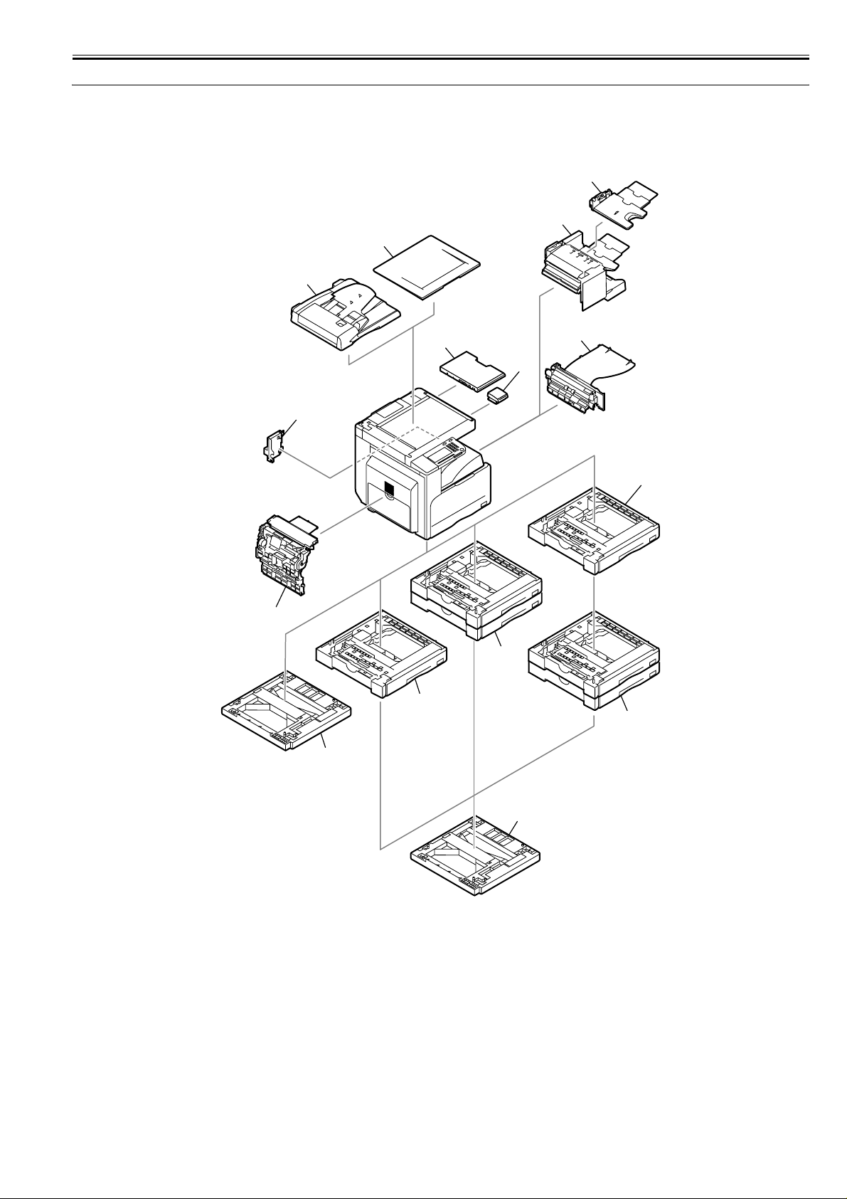
1.1 System Construction
Chapter 1
1.1.1 Pickup/Delivery/Original Handling Accessories System Configuration (iR2018)
iR2018
The configuration is as shown in the following figure:
[3]
[2]
[1]
[11]
[12]
[10]
0017-9181
[4]
[5]
[6]
[9]
[1] DADF-P2
[2] Platen Cover Type J (*1)
[3] Finisher-U2
[4] Additional Finisher Tray-C1
[5] Inner 2-way Tray-E2
[6] Cassette Feeding Module-P1
*1. There are models of the standard equipment.
[7]
[6]
[7]
[8]
[8]
F-1-1
[7] Cassette Feeding Module-Q1
[8] Cassette Heater Attachment Kit-E1
[9] Duplex Unit-B1 (*1)
[10] Power Supply Kit-Q1
[11] Document Tray-J1
[12] Card Reader-E1
1-1
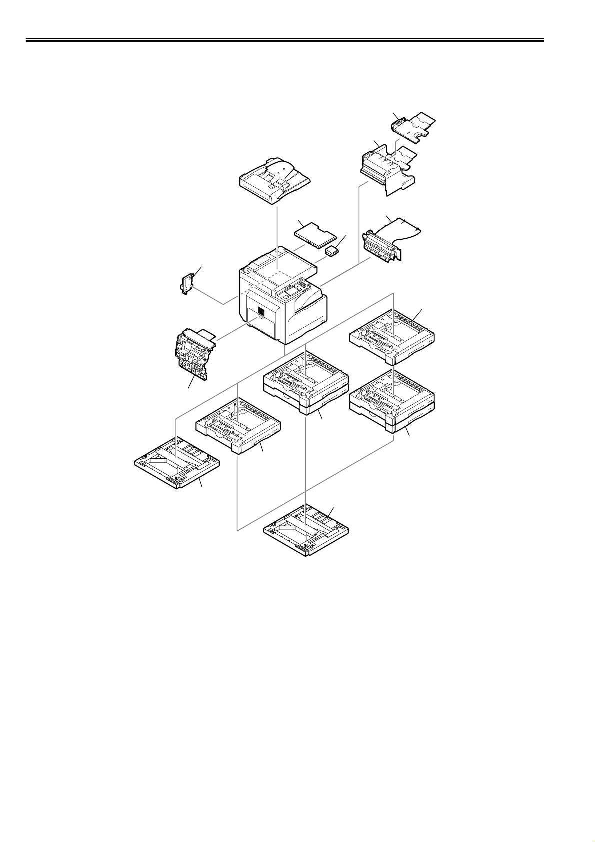
Chapter 1
1.1.2 Pickup/Delivery/Original Handling Accessories System Configuration (iR2018i)
iR2018i
The configuration is as shown in the following figure:
[1]
[9]
[10]
[8]
0017-9182
[2]
[3]
[4]
[1] Finisher-U2
[2] Additional Finisher Tray-C1
[3] Inner 2-way Tray-E2
[4] Cassette Feeding Module-P1
[5] Cassette Feeding Module-Q1
*1. There are models of the standard equipment.
[7]
[5]
[5]
[4]
[6]
[6]
F-1-2
[6] Cassette Heater Attachment Kit-E1
[7] Duplex Unit-B1 (*1)
[8] Power Supply Kit-Q1
[9] Document Tray-J1
[10] Card Reader-E1
1-2

Chapter 1
1.1.3 Pickup/ Delivery /Original Handling Accessories System Configuration (iR2022/iR2022N/iR2025/iR2030)
iR2025 / iR2030 / iR2022
The configuration is as shown in the following figure:
[2]
[1]
[10]
[11]
[9]
[4]
[3]
[5]
0017-9183
[8]
[7]
[1] DADF-P2 (*1)
[2] Platen Cover Type J (*1)
[3] Finisher-U2
[4] Additional Finisher Tray-C1
[5] Inner 2-way Tray-E2
[6] Cassette Feeding Module-Q1
*1. There are models of the standard equipment.
[6]
[7]
F-1-3
[7] Cassette Heater Attachment Kit-E1
[8] Duplex Unit-B1 (*1)
[9] Power Supply Kit-Q1
[10] Document Tray-J1
[11] Card Reader-E1
1-3
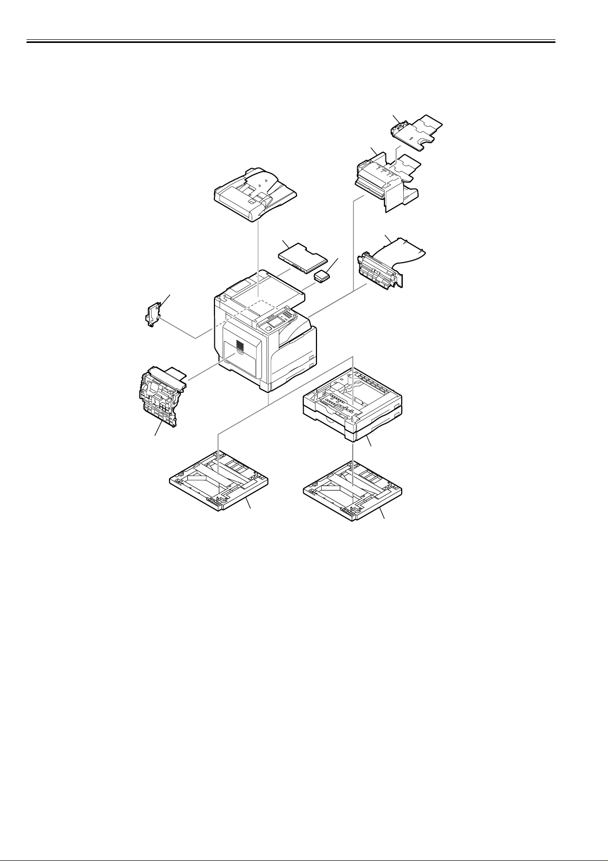
Chapter 1
1.1.4 Pickup/Delivery/Original Handling Accessories System Configuration (iR2022i/iR2022K/iR2025i/iR2030i)
iR2022i / iR2025 / iR2030
The configuration is as shown in the following figure:
[2]
[1]
[8]
[9]
[7]
[3]
0017-9187
[6]
[1] Finisher-U2
[2] Additional Finisher Tray-C1
[3] Inner 2-way Tray-E2
[4] Cassette Feeding Module-Q1
[5] Cassette Heater Attachment Kit-E1
*1. There are models of the standard equipment.
[4]
[5]
[5]
F-1-4
[6] Duplex Unit-B1 (*1)
[7] Power Supply Kit-Q1
[8] Document Tray-J1
[9] Card Reader-E1
1-4
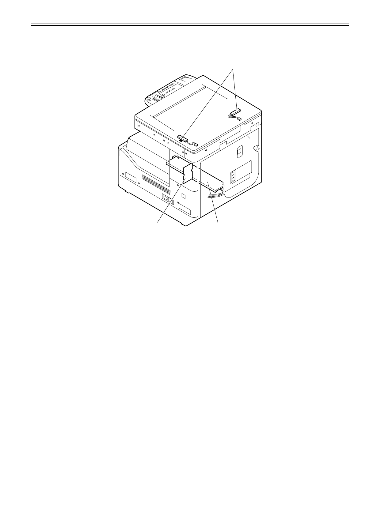
Chapter 1
1.1.5 Reader Heater/Cassette Heater System Conf iguration (iR2018/iR2022/iR2022N)
iR2018 / iR2022
The configuration is as shown in the following figure:
[1]
0017-9191
[2][3]
F-1-5
[1] Reader Heater (*1)
[2] Cassette Heater (*1)
[3] Heater PCB
*1: To operate the heaters, a heater PCB is required. These parts are supplied as service parts, not the standard items.
1-5
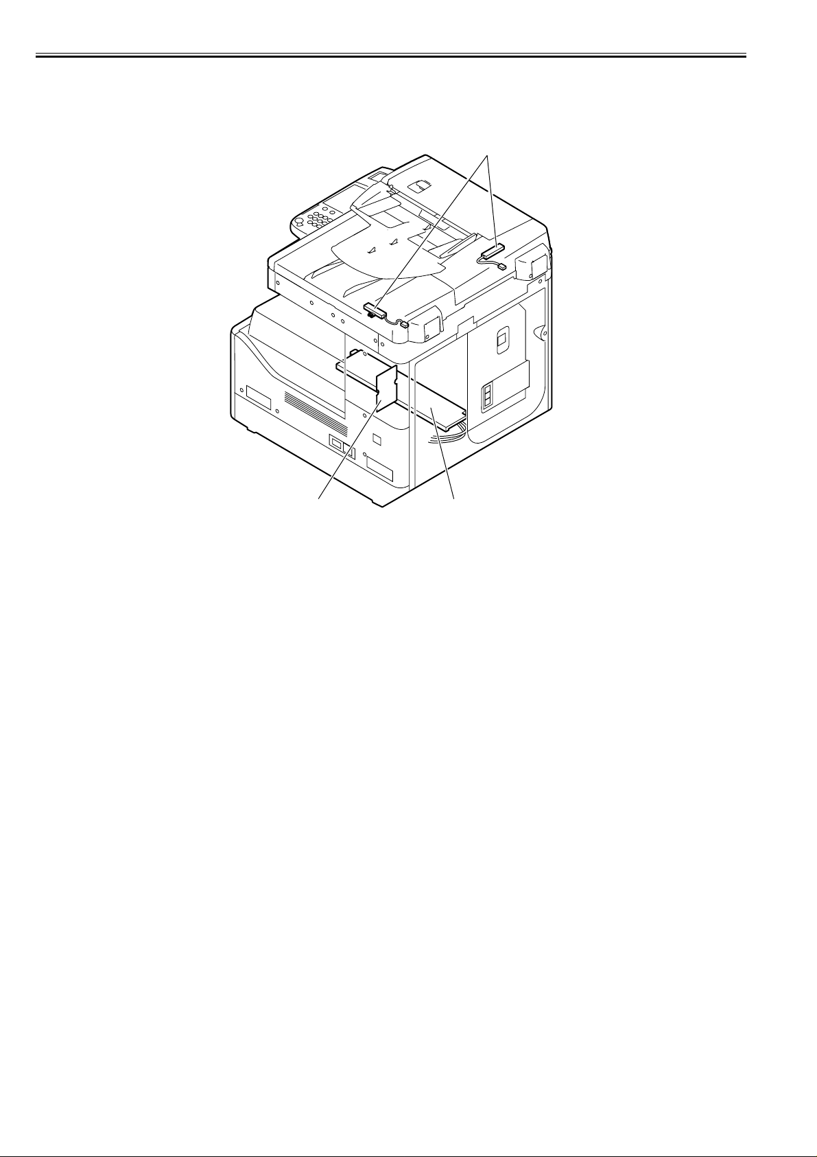
Chapter 1
1.1.6 Reader Heater/Cassette Heater System Configuration (iR2018i)
iR2018i
The configuration is as shown in the following figure:
0017-9193
[1]
[3]
F-1-6
[1] Reader Heater (*1)
[2] Cassette Heater (*1)
[3] Heater PCB
[2]
*1: To operate the heaters, a heater PCB is required. These parts are supplied as service parts, not the standard items.
1-6

Chapter 1
1.1.7 Reader Heater/Cassette Heater System Configuration (iR2022K/iR2022i/iR2025/iR2025i/iR2030/iR2030i)
iR2022i / iR2025 / iR2030
The configuration is as shown in the following figure:
[1]
0017-9194
[3]
F-1-7
[1] Reader Heater (*1)
[2] Cassette Heater (*1)
[3] Heater PCB
[2]
*1: To operate the heaters, a heater PCB is required. These parts are supplied as service parts, not the standard items.
1-7

Chapter 1
1.1.8 Printing/Transmitting Accessories System Configuration (iR2018/ir2022/iR2022N)
iR2018 / iR2022
The configuration is as shown in the following figure:
[1]
[3]
0017-9196
[2]
[4]
[5]
[8]
[7]
F-1-8
FAX Panel-A1 (*2) [5] PCL Printer Kit-V1/W1 (*3)
[1]
[2] Barcode Printing Kit-B1 (license certificate) [6] SUPER G3 FAX BD-AA1 (*2)
UFRII LT P.Kit-V1 (*1) [7] iR128MB EXP.RAM-E1
[3]
Serial Interface Board-A2 [8] Serial Interface Kit-H1
[4]
[6]
*1. There are models of the standard equipment.
*2: To make the FAX feature effective, a FAX panel and a super G3 FAX board are required.
*3: The PCL printer kit contains a 128MB expansion RAM.
1-8

Chapter 1
1.1.9 Printing/Transmitting Accessories System Configuration (iR2018i/iR2022i/iR2022K/iR2025/iR2025i/iR2030/iR2030i)
iR2022i / iR2025 / iR2030 / iR2018i
The configuration is as shown in the following figure:
[1]
[2]
[3]
0017-9197
[1] UFRII LT P.Kit-V1 (*1)
[2] Serial Interface Board-A2
[3] PCL Printer Kit-V1/W1 (*1)
[4] SUPER G3 FAX BD-AA1 (*1)
*1. There are models of the standard equipment.
[7]
[4]
[5]
[6]
F-1-9
[5] Color SEND Kit-L1 (license certificate) (*1)
[6] Barcorde Printing Kit-B1 (license certificate)
[7] Serial Interface Kit-H1
1-9

Chapter 1
1.1.10 Functions of the Printing/Transmission Functions (iR2018/iR2022/iR2022N)
iR2018 / iR2022
The following is a brief explanation of the functions expected of the accessories; for details, see the chapters that follow:
UFR II printer function (Resolution: 600dpi) ==> UFRII LT Printer Kit-V1
UFR II printer function (Resolution: 1200dpi) ==> UFRII LT Printer Kit-V1
iR 128MB Expansion RAM-E1
PCL print function ==> PCL Printer Kit-V1
FAX function ==> Super G3 FAX Board-AA1
FAX Panel-A1
Coin vender function ==> Serial Interface board-A2
Coin vender function (RS232C type) ==> Serial Interface kit-H1
Barcode print function ==> Barcode Printing Kit-B1
1.1.11 Functions of the Printing/Transmission Functions (iR2018i/iR2022i/iR2022K/iR2025/iR2025i/IR2030/iR2030i)
iR2022i / iR2025 / iR2030 / iR2018i
The following is a brief explanation of the functions expected of the accessories; for details, see the chapters that follow:
Color Send Kit-L1
UFR II printer function (Resolution: 1200dpi) ==> UFRII LT Printer Kit-V1
0017-5905
0017-5906
PCL print function ==> PCL Printer Kit-W1
FAX function ==> Super G3 FAX Board-AA1
Coin vender function ==> Serial Interface board-A2
Coin vender function (RS232C type) ==> Serial Interface kit-H1
Color SEND function ==> Color Send Kit-L1
Barcode print function ==> Barcode Printing Kit-B1
1.2 Product Specifications
1.2.1 Names of Parts
1.2.1.1 External View (iR2030i/iR2025i/iR2022i)
iR2022i
0017-5916
1-10

[12]
[11]
[10]
Chapter 1
[1]
[13] [14]
[2]
[3]
[4]
[5]
[15]
[9]
[8]
[7]
[1] DADF [10] Left door
[2] Reader front cover [11] Left cover (rear)
[3] Control panel [12] Reader left cover
[4] Delivery tray [13] Reader right cover
[5] Front cover [14] Reader rear cover
[6] Cassette 1 [15] Rear cover
[7] Cassette 2 [16] Right cover (upper)
[8] Left cover (front) [17] Right cover (lower)
[9] Manual feed tray
1.2.1.2 External View (iR2020/iR2020N/iR2030/iR2025)
iR2025 / iR2030 / iR2022
[1]
[12]
[11]
[10]
[6]
F-1-10
[17]
[16]
0017-6950
[14]
[13]
[2]
[3]
[4]
[15]
[5]
[6]
[9]
[7]
[18]
[16]
[8] [17]
F-1-11
[1] Copyboard cover (*1) [10] Left door
[2] Reader front cover [11] Left cover (rear)
[3] Control panel [12] Reader left cover
[4] Delivery tray [13] Reader right cover
[5] Front cover [14] Reader erar cover
[6] Cassette 1 [15] Rear cover
[7] Cassette 2 [16] Cassette rear cover
[8] Left cover (front) [17] Right cover (upper)
[9] Manual feed tray [18] Right cover (lower)
*1: This accessory comes standard with the models for Asia excluding and the models for some Latin American countries. Other models are available optionally.
1.2.1.3 External View (iR2018i)
iR2018i
1-11
0017-5918

Chapter 1
[11]
[10]
[9]
[1]
[12] [13]
[2]
[3]
[4]
[5]
[14]
[1] DADF [9] Left door
[2] Reader front cover [10] Left cover (rear)
[3] Control panel [11] Reader left cover
[4] Delivery tray [12] Reader right cover
[5] Front cover [13] Reader rear cover
[6] Cassette 1 [14] Rear cover
[7] Left cover (front) [15] Right cover (upper)
[8] Manual feed tray [16] Right cover (lower)
1.2.1.4 External View (iR2018)
iR2018
[11]
[10]
[9]
[8]
[6]
[16]
[7] [15]
F-1-12
[1]
[12]
[2]
[3]
[4]
[5]
0017-5917
[13]
[14]
[6]
[8]
[7]
[1] Copyboard cover (*1) [9] Left door
[2] Reader front cover [10] Left cover (rear)
[3] Control panel [11] Reader left cover
[4] Delivery tray [12] Reader right cover
[5] Front cover [13] Reader erar cover
[6] Cassette 1 [14] Rear cover
[7] Left cover (front) [15] Right cover (upper)
[8] Manual feed tray [16] Right cover (lower)
[16]
F-1-13
*1: This accessory comes standard with the models for Asia and the models for some Latin American countries. Other models are available optionally.
[15]
1.2.1.5 Cross-Section
iR2022i / iR2025 / iR2030 / iR2018 / iR2022 / iR2018i
1-12
0017-5919

Chapter 1
[1]
[18]
[17]
[16]
[15]
[14]
[13]
[2]
[3]
[4]
[5]
[6]
[12][11][10] [9] [8] [7]
F-1-14
[1] CIS unit [10] Separation roller
[2] Reader unit [11] Vertical path roller
[3] Laser scanner unit [12]
[4] DC power supply PCB [13]
[5] HVT PCB [14]
[6] Cassette [15]
[7] Toner bottle [16]
[8] Pickup roller [17]
[9] Feed roller [18]
1.2.2 Using the Machine
1.2.2.1 Turning On the Power Switch (iR2018/iR2022/iR2022N)
iR2018 / iR2022
Manual feed pickup roller
Registration roller
Transfer roller
Drum unit
Pressure roller
Fixing film unit
Delivery roller
0017-5920
1-13

Chapter 1
The machine possesses 2 power switches: main power switch and control power switch. Normally (i.e., unless the machine is in a sleep state), the machine will be
supplied with power when you turn on its main power switch.
[1]
[2]
[3]
F-1-15
[1]Control panel power switch
[2]Main power lamp
[3]Main power switch
1.2.2.2 Turning On the Power Switch (iR2018i/iR2020i/iR2020K/iR2025/iR2025i/iR2030/iR2030i)
iR2022i / iR2025 / iR2030 / iR2018i
0017-5921
1-14

Chapter 1
The machine possesses 2 power switches: main power switch and control power switch. Normally (i.e., unless the machine is in a sleep state), the machine will be
supplied with power when you turn on its main power switch.
[1]
[2]
[3]
F-1-16
[1]Control panel power switch
[2]Main power lamp
[3]Main power switch
1.2.2.3 When Turning Off the Main Power Switch (iR2018/iR2022/iR2022N)
iR2018 / iR2022
0017-5922
1-15

Chapter 1
<During printing or fax data transmission/reception>
Be sure to operate the main power switch while the Processing/Data lamp on the control panel is not lit.
(Turning off the main switch during printing or fax data transmission/reception can erase the data being processed.)
F-1-17
<During downloading>
Do not turn off the power switch or ON/OFF switch on the control panel.
(Turning off the main power switch during downloading can make this machine inoperative.)
1-16
F-1-18

Chapter 1
1.2.2.4 When Turning Off the Main Power Switch (iR2018i/iR2022i/iR2022K/iR2025/iR2025i/iR2030/iR2030i)
iR2022i / iR2025 / iR2030 / iR2018i
<During printing or fax data transmission/reception>
Be sure to operate the main power switch while the Processing/Data lamp on the control panel is not lit.
(Turning off the main switch during printing or fax data transmission/reception can erase the data being processed.)
0017-5923
F-1-19
<During downloading>
Do not turn off the power switch or ON/OFF switch on the control panel.
(Turning off the main power switch during downloading can make this machine inoperative.)
F-1-20
1-17

Chapter 1
1.2.2.5 Control Panel
iR2022i / iR2025 / iR2030 / iR2018 / iR2022 / iR2018i
[1] Touch Panel Display [10] Start key
[2] COPY key [11] Clear key
[3] SEND key [12] Main power indicator
[4] SCAN key [13] Log IN/Out key
[5] Reset key [14] Error indicator
[6] Control panel power switch [15] Additional functions key
[7] Counter Check key [16] Processing/Date indicator
[8] Numeric keys [17] Display Contrast Dial
[9] Stop key
1.2.3 User Mode Items
0017-5926
[1]
[4]
SCAN
[14] [12][17] [15]
[6][2] [3] [5]
[7]
[8]
[9]
[10]
[11][16] [13]
F-1-21
1.2.3.1 Common Settings (iR2030i/iR2030/iR2025i/iR2025/iR2022i/iR2018i)
iR2022i / iR2025 / iR2030 / iR2018i
T-1-1
Item Settings
Initial Function Select Initial Function: Copy*1, Send, Scan
Auto Clear Setting Initial Function*1, Selected Function
Audible Tones Entry Tone: On *1 (1*1 to 3 levels)*2, Off
Toner Save Mode High, Low, Off*1
Printer Density 1 to 9 levels; 5*1
Inch Entry On*1, Off
Drawer Eligibility For APS/ADS Copy
Set System Monitor Screen as initial function: On, Off*1
Set [Device] as the default for System Monitor: On*1, Off
Error Tone: On *1 (1*1 to 3 levels)*2, Off
Send Done Tone: On (1 to 3 levels)*2, Off*1
Receive Done Tone: On (1 to 3 levels)*2, Off*1
Print Done Tone: On *1 (1*1 to 3 levels)*2, Off
Scan Done Tone: On *1 (1*1 to 3 levels)*2, Off
Stack Bypass: On, Off*1
All Other Paper Sources: On*1, Off
Printer
Stack Bypass: cannot be set
All Other Paper Sources: On*1, Off
Receive
Stack Bypass: On, Off*1
All Other Paper Sources: On*1, Off
Other
Stack Bypass: On, Off*1
All Other Paper Sources: On*1, Off
0017-5938
1-18
Register Paper Type Paper Drawer 1, Paper Drawer 2*2, Paper Drawer 3*2, Paper Drawer
4*2: Plain*1, Recycled, Color, 3-hole punch, Bond, Heavy Paper 1
Energy Consumption in Sleep Mode Low*1, High

Item Settings
Tray Designation*2 If the Optional Inner 2 Way Tray-E2 Is Attached:
Tray A: Copy*1, Printer*1, Receive*1, Other*1
Tray B: Copy*1, Printer*1, Receive*1, Other*1
If the Optional Finisher-U2 and Additional Finisher Tray-C1 Are
Attached:
Tray A: Copy*1, Printer*1, Receive*1, Other*1
Tray B: Copy*1, Printer*1, Receive*1, Other*1
Chapter 1
Stack Bypass Standard Settings On: Paper Size, Paper Type
Paper Feed Method Switch Stack Bypass, Paper Drawer 1, Paper Drawer 2*2, Paper Drawer 3*2,
Language Switch On, Off*1
Reversed Display (B/W) On, Off*1
Error Display for Dirty Feeder On*1, Off
Data Compress. Ratio for Remote Scans High Ratio, Normal*1, Low Ratio
Gamma Value for Remote Scans Gamma 1.0, Gamma 1.4, Gamma 1.8*1, Gamma 2.2
Initialize Common Settings Initialize: Yes, No
*1 Indicates the default setting.
*2 Indicates items that appear only when the appropriate optional equipment is attached.
Off*1
Paper Drawer 4*2: Speed*1, Print Side
1.2.3.2 Timer Settings (iR2030i/iR2030/iR2025i/iR2025/iR2022i/iR2018i)
iR2022i / iR2025 / iR2030 / iR2018i
T-1-2
Item Settings
Date & Time Settings Date and Time Setting (12 digit number)
Auto Sleep Time Use Auto Sleep Time: On*1, Off
Auto Clear Time 0 (Off) to 9 minutes, in one minute increments; 2 min.*1
Time Zone Settings:
GMT -12:00 to GMT +12:00;
GMT -5:00*1
Daylight Saving Time Settings: On, Off*1
3 to 30 minutes; 5*1
0017-5939
*1 Indicates the default setting.
1.2.3.3 Adjustment/Cleaning (iR2030i/iR2030/iR2025i/iR2025/iR2022i/iR2018i)
iR2022i / iR2025 / iR2030 / iR2018i
T-1-3
Item Settings
Transfer Roller Cleaning Press [Start].
Drum Cleaning Press [Start].
Fixing Unit Cleaning Cleaning Sheet Print, press [Start].
Feeder Cleaning Press [Start].
Special Mode M Standard*1, Low, Moderate, High
Special Mode N Manual (Medium, High), Off
Special Mode O Stack Bypass: Medium, High, Off*1
Special Mode P Off*1, Medium, High
Bond Special Fixing Mode On, Off*1
Special Mode S Speed Priority 1, Speed Priority 2, Off*1
Rotate Collate Adjustment Speed Priority 1*1, Speed Priority 2, Image Priority
Auto Adjustment for Dirty Feeder On*1, Off
Drawer: Medium, High, Off*1
*1 Indicates the default setting.
1.2.3.4 Report Settings (iR2030i/iR2030/iR2025i/iR2025/iR2022i/iR2018i)
iR2022i / iR2025 / iR2030 / iR2018i
0017-5940
0017-5941
1-19

Chapter 1
T-1-4
Item Settings
Settings TX Report: On, For Error Only*1, Off
Print List Address Book List
Report With TX Image: On*1, Off
Activity Report
Auto Print: On*1, Off
Send/Receive Separate: On, Off*1
RX Report: On, For Error Only, Off*1
One-touch Buttons: Yes, No
Address Book: Yes, No
User's Data List: Yes, No
*1 Indicates the default setting.
1.2.3.5 System Settings (iR2030i/iR2030/iR2025i/iR2025/iR2022i/iR2018i)
iR2022i / iR2025 / iR2030 / iR2018i
T-1-5
Item Settings
System Manager Settings
System Manager 32 characters maximum
System Manager ID Seven digit number maximum
System Password Seven digit number maximum
Department ID Management
Department ID Management On, Off*1
Register ID/Password Register, Edit, Erase, Set page limits
Page Totals Clear, Clear All Totals, Print List
Allow ID Unknown Printer Jobs On*1, Off
Allow ID Unknown Remote Scan Jobs On*1, Off
Network Settings
Forwarding Settings
Receive Type*2 All*1, Fax, I-Fax
Validate/Invalidate On, Off*1
Register Condition Name: 50 characters maximum
Forwarding Conditions
Receive Type: Fax*2, I-Fax
0017-5942
Forward w/o Cond. Receive Type: Fax*2, I-Fax
Detail/Edit Condition Name: 50 Characters maximum
Erase Yes, No
Print List Yes, No
Device Info Settings
Device Name 32 characters maximum
Location 32 characters maximum
User ID Management On, Off*1
Communications Settings
E-mail/I-Fax Settings Maximum TX Data Size: 0 to 99 MB; 3 MB*1
Fax Settings*2 Send Start Speed: 33600 bps*1, 14400 bps, 9600 bps, 7200 bps, 4800
Memory Lock Settings On: Option
Remote UI On/Off On*1 On*1, Off
Restrict the Send Function Address Book Password: 7 digits maximum
Forwarding Destination: Select from the list of registered addresses.
File Format: TIFF*1, PDF, Divide into Pages
Forwarding Conditions
Receive Type: Fax*2, I-Fax
Divided TX over Max.Data Size: On, Off*1
Default Subject: 40 characters maximum; Attached Image*1
bps, 2400 bps
Receive Start Speed: 33600 bps*1, 14400 bps, 9600 bps, 7200 bps,
4800 bps, 2400 bps
Off*1
Restrict New Addresses: On, Off*1
Allow Fax Driver TX: On*1, Off
Restrict Recall: On, Off*1
Confirm Entered Fax Numbers*2: On, Off*1
Restrict Sequential Broadcast: Broadcast Confirmation, Prohibit
Broadcast, Off*1
1-20

Item Settings
License Registration Enter a license key using the numeric keys.
Display Dept. ID/User Name On*1, Off
Auto Online/Offline Auto Online: On, Off*1
Job Log Display On*1, Off
Use USB Device On*1, Off
Failed Forwarding Document Set. Print Image: On*1, Off
PDL Selection (PnP) UFRII LT*1, PCL5e, PCL6, FAX
*1 Indicates the default setting.
*2 Indicates items that appear only when the appropriate optional equipment is attached.
Auto Offline: On, Off*1
Store Image to Memory: On, Off*1
1.2.3.6 Copy Settings (iR2030i/iR2030/iR2025i/iR2025/iR2022i/iR2018i)
iR2022i / iR2025 / iR2030 / iR2018i
T-1-6
Item Settings
Image Orientation Priority On, Off*1
Auto Orientation On*1, Off
Standard Settings Store, Initialize
Initialize Copy Settings Yes, No
*1 Indicates the default setting.
1.2.3.7 Communication Settings (iR2030i/iR2030/iR2025i/iR2025/iR2022i/iR2018i)
iR2022i / iR2025 / iR2030 / iR2018i
Chapter 1
0017-5943
0017-5944
T-1-7
Item Settings
Common Settings: TX Settings
Unit Name 24 characters maximum
Data Compression Ratio High Ratio, Normal*1, Low Ratio
Retry Times 0 to 5 times; 3 times*1
Edit Standard Send Settings Store, Initialize
TX Terminal ID On: Option (Printing Position, Telephone # Mark*2)
Gamma Value for Color Send Jobs Gamma 1.0, Gamma 1.4, Gamma 1.8*1, Gamma 2.2
Sharpness 1 to 7 levels, 4*1
Register Favorites Button M1 to M18
Color TX Scan Settings Speed Priority*1, Image Priorit
Default Screen for Send Favorite Buttons, One-touch Buttons, Initial Function*1
Initialize TX Settings Yes, No
Common Settings: RX Settings
2-Sided Print On, Off*1
Select Cassette Switch A: On*1, Off
Receive Reduction On*1 RX Reduction:
Received Page Footer On, Off*1
Continue Printing When Toner Is Out On, Off*1
Fax Settings: User Settings*2
Unit Telephone # 20 characters maximum
Tel Line Type Pulse, Tone*1
Monitor Volume Control Volume Control: 0 to 3 levels, 1*1
Fax Settings: TX Settings*2
ECM TX On*1, Off
Pause Time 1 to 15 seconds; 2 seconds*1
Switch B: On*1, Off
Switch C: On*1, Off
Switch D: On*1, Off
Auto*1, Fix. Red.
Reduce %: 97, 95, 90*1, 75%
Reduce Direction
Ver. Hor., Vertical Only*1
Off
1-21

Chapter 1
Item Settings
Auto Redial On*1 Option:
Check Dial Tone Before Sending On*1, Off
Rotate Send On*1, Off
Fax Setting: RX Settings*2
ECM RX On*1, Off
Redial Times: 1 to 10 times; 2 times*1
Redial Interval: 2 to 99 minutes; 2*1
minutes*1
TX Error Redial: On*1, Off
Off
*1 Indicates the default setting.
*2 Indicates items that appear only when the appropriate optional equipment is attached.
1.2.3.8 Printer Settings (iR2030i/iR2030/iR2025i/iR2025/iR2022i/iR2018i)
iR2022i / iR2025 / iR2030 / iR2018i
T-1-8
Item Settings
DEFAULT PAPERSIZE LTR*, STMT, EXECUTIV, ISO-B5, ISO-C5, COM10,
DEFAULT PAPERTYPE PLAIN PAPER*, COLOR, RECYCLED, HEAVY PAPER 1,
COPIES 1 to 999; 1*
2-SIDED PRINTING OFF*, ON
PRINT QUALITY
IMAGE REFINEMENT ON*, OFF
DENSITY 9 levels; 5*
TONER SAVER OFF*, ON
PAGE LAYOUT
BINDING LONG EDGE*, SHORT EDG
MARGIN INCHES*: -01.90 INCHES to 01.90 INCHES; 00.00 INCHES*
AUTO ERROR SKIP OFF*, ON
ERROR TIME OUT ON* (TIME OUT PERIOD: 5 to 300 SEC), OFF; 15 SEC*
COLLATE OFF*, COLLATE, ROTATE + COLLATE*1, ROTATE +
INIT. PRINTER SET OFF*, ON
RESET PRINTER OFF*, ON
PCL Settings
PAPER SAVE OFF*, ON
ORIENTATION PORTRAIT*, LANDSCAPE
FONT NUMBER 0 to 89; 0*
POINT SIZE 4.00 to 999.75 point; 12.00 point*
PITCH 0.44 to 99.99 cpi; 10.00 cpi*
FORM LINES 5 to 128 lines; 60 lines*
SYMBOL SET PC8*, PC850, PC852, PC858, PC8DN, PC8TK, PC1004, PSTEXT,
CUSTOM PAPER OFF*, ON
UNIT OF MEASURE INCHES*, MILLIMETERS
X DIMENSION 5.83" to 17.00" (148 mm to 432 mm); 17.00"* (432 mm)
Y DIMENSION 3.75" to 11.69" (95 mm to 297 mm); 11.69"* (297 mm)
APPEND CR TO LF NO*, YES
ENLARGE A4 OFF*, ON
HALFTONE
TEXT TONE, GRADATION, RESOLUTION*
GRAPHICS TONE*, GRADATION, RESOLUTION
IMAGE TONE*, GRADATION, RESOLUTION
BarDIMM*3 ENABLE*, DISABLE
FreeScape ~*, ", #, $, /, \, ?, {, }, |, OFF
MONARCH, DL, A4, A3, B4, B5, A5, 11X17, LGL
HEAVY PAPER 2, HEAVY PAPER 3, BOND, 3-HOLE PUNCH
PAPER, TRANSPARENCY, LABELS, ENVELOPE
MM: -50.0 MM to 50.0 MM; 0.0 MM*
GROUP*1, OFFSET + COLLATE*2, OFFSET + GROUP*2,
STAPLE*2 (STAPLE POSITION: TOP LEFT*, TOP RIGHT,
BOTTOM LEFT)
ROMAN8, ROMAN9, WIN30, WINBALT, WINL1, WINL2,
WINL5, DESKTOP, ISO4, ISO6, ISO11, ISO15, ISO17, ISO21,
ISO60, ISO69, ISOL1, ISOL2, ISOL5, ISOL6, ISOL9, LEGAL,
MCTEXT, PC775
0017-5945
An asterisk(*) indicates the default settings.
1-22

*1 Rotate items do not appear when the optional Finisher-U2 is attached.
*2 Offset and staple items appear only when the optional Finisher-U2 is attached.
*3 This setting is available only if the BarDIMM function is activated.
1.2.3.9 Address Book Settings (iR2030i/iR2030/iR2025i/iR2025/iR2022i/iR2018i)
iR2022i / iR2025 / iR2030 / iR2018i
T-1-9
Item Settings
Register Address: Register New Address
Fax*2 Fax Number: 120 characters maximum
E-mail E-mail Address: 120 characters maximum
I-Fax I-Fax Address: 120 characters maximum
File Protocol: FTP*1, Windows (SMB)
Option: Sending Speed, Long Distance, ECM TX
Register Name: 16 characters maximum
Register Name: 16 characters maximum
Register Name: 16 characters maximum
Host Name: 120 characters maximum
File Path: 120 characters maximum
User: 24 characters maximum
Password: 24 characters maximum (FTP),
14 characters maximum (Windows (SMB))
Register Name: 16 characters maximum
Chapter 1
0017-5946
Group Address Book
Register Address: Erase
Register Address: Edit
One-touch Buttons
Register/Edit You can register or edit the items of One-touch Buttons for Fax, E-
*1 Indicates the default setting.
*2 Indicates items that appear only when the appropriate optional equipment is attached.
1.2.3.10 Recommended setting of system management information
iR2022i / iR2025 / iR2030 / iR2018 / iR2022 / iR2018i
When multiple users use the machine, it is necessary to advise each user to set the system management information.
Setting ID and password of system administrator on the operation unit under (Additional functions key) > [System management setting] > [Setting of system administrator's information] has an effect of restraining the third person from falsifying information, for the ID and password are required when a user carries out an
important setting of the machine.
Under the environment that the setting is not done, if a user who does not sufficiently know operation situation of the machine tries to change the setting, following
troubles may occur.
- When the user changes [User ID Management] from [off] to [on], copying operation cannot be done unless ID and password are input.
- When each setting is changed on the network from RUI, that enables to falsify data of address book or delete log.
- When TCP/IP fixed address is changed on the network setting, printing operation via network cannot be done until the port setting is changed.
- When usage restriction of USB device is changed to [on], printing operation via USB becomes disabled.
1.2.3.11 The Reference Information of the Department ID Management
iR2022i / iR2025 / iR2030 / iR2018 / iR2022 / iR2018i
Function:
If Department is registered in Department ID Management, users are required to input the Department ID and password when inputting data from the operation
unit of the machine. Also, the registration enables to restrict usage and control the usage number of times of Total Parts, Copy, B&W Scan, Color Scan, or Print.
Setting method:
Register Department ID in Department ID Management under Additional Functions key>System Setting.
Operation outline:
Department ID can be registered in [Department ID management] from the operation unit of the machine even though [System Manager Settings] is not done.
When registering data in [Department ID Management] using RUI, you need to registe r yo urself as a system mana ger in [S ystem Manager Setti ngs] and login
as a system manager.
Erase
Register Name: 16 characters maximum
mail, I-Fax,
File, and Group shown in Register New Add above.
Key Name: 12 characters maximum
0017-5948
0017-5949
1.2.4 Maintenance by the User
1.2.4.1 User Maintenance Items
iR2022i / iR2025 / iR2030 / iR2018 / iR2022 / iR2018i
No. Item Maintenance cycle Remarks
[1] Pressure plate cleaning As required
[2] Copyboard glass(large) cleaning As required
[3] Copyboard glass(small) cleaning When the message appears
[4] Copyboard holder (jump board) As required
[5] Fixing pressure roller cleaning As required Clean every 10000 sheets
0017-5951
1-23

Chapter 1
[6] Exterior cleaning As required
1.2.4.2 Cleaning (LCD type)
iR2018 / iR2022
The parts that should be cleaned by the customer to maintain the design performance and the cleaning method are described below.
The service engineer should instruct the customer to clean the machine at regular intervals (once a month).
1. Pressure Plate
Clean the pressure plates [1] with a cloth dampened with water or neutral detergent and squeezed hard, and then wipe it with a dry soft cloth.
[1]
F-1-22
2. Document Glass/Glass holder (jump board)
Clean the document glass [1] with a cloth dampened with water or neutral detergent and squeezed hard, and then wipe them with a dry soft cloth.
When an ADF is installed, clean is document glass (small) [2] and glass holder [3] in the same manner.
[1]
[2]
0017-5953
[3]
F-1-23
3. Cleaning the Fixing Pressure Roller
If white streaks are seen on the printed paper, the fixing pressure roller can b e dirt y. If w hite str eaks a re seen on the pr inted pape r, clean the fi xing pressure r oller
in the user mode. Be sure to clean the fixing pressure roller after replacing the toner bottle.
When cleaning the fixing pressure roller, manually feed A4 paper.
MEMO:
The time required for cleaning is about 100 seconds.
1) Press the user mode key " " to enter the user mode.
2) Using the left an right arrow keys, display the "ADJUST./CLEANING" menu.
3) Press the OK key.
4) Using the left and right arrow keys, select "FIX. UNIT CLEANING". Next press the OK key.
5) Using the left and right arrow keys, select "CLEAN PAPER PRT". Next press the OK key. A cleaning pattern will be printed.
6) Open the manual feed tray.
1-24
F-1-24

7) Place the cleaning pattern printed in step 5 in the manual feed tray with "V" up.
F-1-25
8) Using the left and right arrow keys, select "START CLEANING".
9) Press the OK key. Cleaning will start.
1.2.4.3 Cleaning (Touch panel type)
iR2022i / iR2025 / iR2030 / iR2018i
The parts that should be cleaned by the customer to maintain the design performance and the cleaning method are described below.
The service engineer should instruct the customer to clean the machine at regular intervals (once a month).
1. Pressure Plate
Clean the pressure plates [1] with a cloth dampened with water or neutral detergent and squeezed hard, and then wipe it with a dry soft cloth.
Chapter 1
0017-5955
[1]
F-1-26
2. Document Glass/Glass holder (jump board)
Clean the document glass [1] with a cloth dampened with water or neutral detergent and squeezed hard, and then wipe them with a dry soft cloth.
When an ADF is installed, clean is document glass (small) [2] and glass holder [3] in the same manner.
[1]
[2]
[3]
F-1-27
3. Cleaning the Fixing Pressure Roller
If white streaks are seen on the printed paper, the fixing pressure roller can be dir ty. If white streaks are seen on the printed paper, cl ean the fixing pre ssure roller
in the user mode.
When cleaning the fixing pressure roller, manually feed A4 paper.
MEMO:
The time required for cleaning is about 100 seconds.
1-25

Chapter 1
1) Press the Additional functions key to enter the user mode.
2) Select "Adjustment/Cleaning" on the touch panel.
3) Select "Fixing Unit Cleaning" and then press [Cleaning Sheet Print]. The cleaning pattern will be printed.
4) Open the manual feed tray.
F-1-28
5) Place the cleaning pattern printed in step 3 in the manual feed tray with "V" up.
F-1-29
6) Select the size of the loaded paper and then press [Next].
7) Select the size of the loaded paper and then press [OK].
8) Press [Start] and then Cleaning will start.
1.2.5 Safety
1.2.5.1 Safety of the Laser Light
iR2022i / iR2025 / iR2030 / iR2018 / iR2022 / iR2018i
Laser light can prove to be hazardous to the human body. The machine's laser unit is fully enclosed in a protective housing and external covers so that its light will
not escape outside as long as the machine is used normally.
1.2.5.2 CDRH Regulations
iR2022i / iR2025 / iR2030 / iR2018 / iR2022 / iR2018i
The Center for Devices and Radiological Health of the US Food and Drum Administration put into force regulations concerning laser products on August 2, 1976.
These regulations apply to laser products manufactu red on and after August 1, 1976, and the sale of laser products not certified under the regulations is banned
within the Untied States. The label shown here indicates compliance with the CDRH regulations, and its attachment is required on all laser products that are sold
in the United States.
0017-2608
0017-2609
CANON
30-2, SHIMOMARUKO, 3-CHOME, OHTAKU, TOKYO,
146, JAPAN.
MANUFACTURED:
THIS PRODUCT CONFORMS WITH DHHS RADIATION
PERFORMANCE STANDARD 21CFR CHAPTER 1
SUBCHAPTER J.
1-26
F-1-30

Chapter 1
1.2.5.3 Handling the Laser Unit
iR2018 / iR2022
The laser scanner unit emits invisible laser light inside it. If exposed to laser light, the human eye can irreparably be damaged. Never attempt to disassembl e the
laser scanner unit. (It is not designed for servicing in the field.)
0017-2610
Warning labels are affixed to the top cover of the laser scanner unit and the inner cover inside the front cover of this machine.
F-1-31
1.2.5.4 Handling the Laser Unit
iR2022i / iR2025 / iR2030 / iR2018i
The laser scanner unit emits invisible laser light inside it. If exposed to laser light, the human eye can irreparably be damaged. Never attempt to disassembl e the
laser scanner unit. (It is not designed for servicing in the field.)
Warning labels are affixed to the top cover of the laser scanner unit and the inner cover inside the front cover of this machine.
0017-2611
1-27

Chapter 1
F-1-32
1.2.5.5 Safety of Toner
iR2022i / iR2025 / iR2030 / iR2018 / iR2022 / iR2018i
0017-2612
The machine's toner is a non-toxic material made of plastic, iron, and small amounts of dye.
Do not throw toner into fire. It may cause explosion.
Toner on Clothing or Skin
1. If your clothing or skin has come into contact with toner, wipe it off with tissue; then, wash it off with water.
2. Do not use warm water, which will cause the toner to jell and fuse permanently with the fibers of the cloth.
3. Do not bring toner into contact with plastic material. It tends to react easily.
1.2.5.6 Point to Note about Fire
iR2022i / iR2025 / iR2030 / iR2018 / iR2022 / iR2018i
It is dangerous to throw lithium batteries and parts and components containing flammable substances, such as cartridges, etc., into fire. Such parts and components
must be disposed of in accordance with local laws and regulations.
1.2.5.7 Cautions as to the replacement and disposal of lithium battery
iR2022i / iR2025 / iR2030 / iR2018 / iR2022 / iR2018i
Risk of explosion if Battery is replaced by an incorrect type.
Dispose of used Batteries according to the instructions.
0017-2613
0017-2614
1-28

1.2.6 Product Specifications
Chapter 1
1.2.6.1 Product Specifications
iR2022i / iR2025 / iR2030 / iR2018 / iR2022 / iR2018i
Copyboard stream reading, fixed reading
Body desktop
Light source type LED array (CIS)
Photosensitive medium OPC drum (30-mm dia.)
Image reading method CCD (CIS)
Reproduction method indirect electrostatic
Exposure method by laser light
Charging method by AC charging roller
Development method 1-component toner projection
Transfer method by transfer roller
Separation method by curvature + static eliminator
Cassette pickup method retard
Multifeeder pickup method dual processing
Drum cleaning method by cleaning blade
Fixing method on-demand
Delivery method face-down
Reproduction ratio 50% to 200%
Warm-up time approx. 26sec
Image margin (leading edge) 3.0 -/+1.5 mm
Image margin (trailing edge) 3.0 -/+2.0 mm
Image margin (left/right) left edge: 3.0 -/+2.0 mm
Non-image width (leading edge) 3.0 -/+2.0 mm
Non-image width (trailing edge) 5.0 -/+2.0 mm
Non-image width (left/right) 3.0 -/+2.0 mm
Number of gradations 256 gradations
Reading resolution 600 x 600 dpi
Printing resolution 1200 dpi x 1200 dpi
First print time 6.9 sec or less
Cassette capacity 250sheets (80 g/m2)
Multifeeder tray capacity 100 sheets (A4/B5/LTR, 64 g/m2)
Continuous reproduction 1 to 99 sheets
Toner type magnetic negative toner
Original type sheet, book
Maximum original size A3/LDR
Original size detection function by reflection type sensor (iR2018/2018N/2018i: Non-equipment)
Sleep mode yes
Option See the system configuration chart.
Operating environment
(temperature range)
Operating environment
(humidity range)
Operating environment
(atmospheric pressure)
Noise iR2030 series: 69.5 dB or less
Power supply rating 120/230V
Power consumption (maximum) 120V model: 1423 W or less
right edge: 0.5 mm or more
50 sheets (A3/B4/LDR/LGL, 64 g/m2)
100 sheets (A5/A5R/STMT, 64 g/m2)
80 sheets (A4/B5/LTR, 80 g/m2)
50 sheets (A3/B4/LDR/LGL, 80 g/m2)
80 sheets (A5/A5R/STMT, 80 g/m2)
50 sheets (heavy paper, A4/B5/LTR, 105 g/m2)
50 sheets (heavy paper, A3/B4/LDR/LGL, 105 g/m2)
50 sheets (heavy paper, A5/A5R/STMT, 105 g/m2)
50 sheets (heavy paper, A4/B5/LTR, 128 g/m2)
35 sheets (heavy paper, A3/B4/LDR/LGL, 128 g/m2)
50 sheets (heavy paper, A5/A5R/STMT, 128 g/m2)
50 sheets (OHP)
1 sheet (label)
10 sheets (envelope)
40 sheets (post card)
15 to 27.5 deg C
25% to 75%
0.6 to 1.0 atm
iR2025 series: 67.75 dB or less
iR2022 series: 66.7 dB or less
iR2018 series: 65.5 dB or less
230V model: 1499 W or less
0017-2617
1-29

Chapter 1
Power consumption Average power consumption
Ozone 0.01 ppm or less (initial)
Dimensions Platen/1-casette model: 622mm x 638mm x 580.4mm (WxDxH)
Weight Platen/1-casette model: approx. 41 kg
1.2.7 Function List
1.2.7.1 Printing Speed (iR2030/iR2030i)
iR2030
120V model: 646 W or less (At the option full-equipped: 690 W)
230V model: 612 W or less (At the option full-equipped: 622 W)
0.035 ppm or less (after endurance)
Platen/2-casettes model: 622mm x 638mm x 665.4mm (WxDxH)
ADF/1-casette model: 622mm x 676mm x 672mm (WxDxH)
ADF/2-casettes model: 622mm x 676mm x 757mm (WxDxH)
Platen/2-casettes model: approx. 47 kg
ADF/1-casette model: approx. 47 kg
ADF/2-casettes model: approx. 53 kg
0017-5909
1-30

Paper size Single-sided Double-sided
Casette feed Manual feed Casette feed Manual feed
Plain paper A4 30 30 27.5 27.5
A5 25.5 25.5 - -
A5R - 9.5 - 9
B5 23 23 22.5 22.5
B5R9999
A4R 11 11 9.5 9.5
B4 11 11 9 9
A3 15 15 10 10
STMT 10.5 10.5 - 9
STMTR - 9.5 - 9
EXE - 23 - 21
LTR 30 30 27.5 27.5
LTRR 11.5 11.5 9.5 9.5
LGL 11 11 9 9
LDR 15 15 9.5 9.5
8K 10.5 10.5 9 9
16K 23 23 22.5 22.5
16KR 11 11 9 9
Heavy paper; 81 to 105g/
m2 *1
(Heavy paper; 106 to
128g/m2 *2)
Bond paper *3
(Bond paper H *4)
OHP A4 - 30 - -
Envelope Monarch - 6.1 - -
Postcard Postcard - 11.5 - -
A4 23 (-) 23 (23) 22 (-) 22 (-)
A5 47.5 (-) 17.5 (7.5) - -
A5R - 10 (7) - 8 (-)
B5 16.5 (-) 16.5 (8) 16 (-) 16 (-)
B5R 8 (-) 8 (7.5) 7.5 (-) 7.5 (-)
A4R 9.5 (-) 9.5 (5.5) 9 (-) 9 (-)
B4 9.5 (-) 9.5 (6.5) 8.5 (-) 8.5 (-)
A3 14 (-) 14 (14) 9.5 (-) 9.5 (-)
STMT 9 (-) 9 (8) - 8 (-)
STMTR - 8 (7.5) - -
EXE - 16.5 (8) - 15.5 (-)
LTR 22.5 (-) 22.5 (22.5) 22 (-) 22 (-)
LTRR 9.5 (-) 9.5 (4.5) 9 (-) 9 (-)
LGL 9.5 (-) 9.5 (4.5) 8.5 (-) 8.5 (-)
LDR 13.5 (-) 13.5 (13.5) 9.5 (-) 9.5 (-)
8K 9 (-) 9 (4.5) 8 (-) 8 (-)
16K 16.5 (-) 16.5 (8) 16 (-) 16 (-)
16KR 9.5 (-) 9.5 (4.5) 8.5 (-) 8.5 (-)
A4 - 7.5 (6) - 7.5 (6)
A5 -6 (5)- -
A5R - 6 (5) - 6 (4.5
B5 -6 (5)-6 (5)
B5R - 5.5 (4.5) - 5.5 (4)
A4R - 4.5 (4) - 4.5 (3.5)
B4 - 5.5 (4.5) - 5 (4)
A3 -6 (5)-6 (5)
STMT 6.5 (5) 6.5 (5) - -
STMTR - 6 (5) - 5.5 (4.5)
EXE - 6 (5) - LTR 7.5 (6) 7.5 (6) 7.5 (6) 7.5 (6)
LTRR 4.5 (4) 4.5 (4) 4.5 (3) 4.5 (3)
LGL 4 (3.5) 4 (3.5) 3.5 (3) 3.5 (3)
LDR 6 (5) 6 (5) 6 (5) 6 (5)
8K----
16K----
16KR----
LTR - 30 - -
COM10 - 6 - -
ISO-B5 - 6.1 - ISO-C5 - 6 - -
DL - 6 - -
Double postal card - 10.5 - -
4-plane post card - 23.5 - -
Chapter 1
1-31

Chapter 1
*1. Bond SP. FIX. Mode in the user mode: OFF
*2. Bond SP. FIX. Mode in the user mode: ON
Supplement:
- The above copy speed does not change irrespective of whether paper is supplied from the upper/lower cassette, the manual feed tray, or from the cassette feeding
module.
- The copy speed may become down when the copies make continuously one minutes or more with the narrow width paper. The slowdown is reduced with the
following user mode. User Mode: Additional Functions > Adjust/Cleaning > Spesial Mode S > Speed Priority 1 or 2
1.2.7.2 Printing Speed (iR2025/iR2025i)
iR2025
0018-0333
1-32

Chapter 1
1-33

Chapter 1
T-1-10
Paper size Single-sided Double-sided
Casette feed Manual feed Casette feed Manual feed
Plain paper A4 25 25 23.5 23.5
A5 25.5 25.5 - -
A5R - 9.5 - 9
B5 23 23 22.5 22.5
B5R9999
A4R 11 11 9.5 9.5
B4 11 11 9 9
A3 15 15 10 10
STMT 10.5 10.5 - 9
STMTR - 9.5 - 9
EXE - 23 - 21
LTR 25 25 27.5 27.5
LTRR 11.5 11.5 9.5 9.5
LGL 11 11 9 9
LDR 15 15 9.5 9.5
8K 10.5 10.5 9 9
16K 23 23 22.5 22.5
16KR 11 11 9 9
Heavy paper; 81 to 105g/
m2 *1
(Heavy paper; 106 to
128g/m2 *2)
Bond paper *3
(Bond paper H *4)
OHP A4 - 30 - -
Envelope Monarch - 6.1 - -
Postcard Postcard - 11.5 - -
A4 23 (-) 23 (23) 22 (-) 22 (-)
A5 47.5 (-) 17.5 (7.5) - A5R - 10 (7) - 8 (-)
B5 16.5 (-) 16.5 (8) 16 (-) 16 (-)
B5R 8 (-) 8 (7.5) 7.5 (-) 7.5 (-)
A4R 9.5 (-) 9.5 (5.5) 9 (-) 9 (-)
B4 9.5 (-) 9.5 (6.5) 8.5 (-) 8.5 (-)
A3 14 (-) 14 (14) 9.5 (-) 9.5 (-)
STMT 9 (-) 9 (8) - 8 (-)
STMTR - 8 (7.5) - -
EXE - 16.5 (8) - 15.5 (-)
LTR 22.5 (-) 22.5 (22.5) 22 (-) 22 (-)
LTRR 9.5 (-) 9.5 (4.5) 9 (-) 9 (-)
LGL 9.5 (-) 9.5 (4.5) 8.5 (-) 8.5 (-)
LDR 13.5 (-) 13.5 (13.5) 9.5 (-) 9.5 (-)
8K 9 (-) 9 (4.5) 8 (-) 8 (-)
16K 16.5 (-) 16.5 (8) 16 (-) 16 (-)
16KR 9.5 (-) 9.5 (4.5) 8.5 (-) 8.5 (-)
A4 - 7.5 (6) - 7.5 (6)
A5 -6 (5)- A5R - 6 (5) - 6 (4.5
B5 -6 (5)-6 (5)
B5R - 5.5 (4.5) - 5.5 (4)
A4R - 4.5 (4) - 4.5 (3.5)
B4 - 5.5 (4.5) - 5 (4)
A3 -6 (5)-6 (5)
STMT 6.5 (5) 6.5 (5) - -
STMTR - 6 (5) - 5.5 (4.5)
EXE - 6 (5) - LTR 7.5 (6) 7.5 (6) 7.5 (6) 7.5 (6)
LTRR 4.5 (4) 4.5 (4) 4.5 (3) 4.5 (3)
LGL 4 (3.5) 4 (3.5) 3.5 (3) 3.5 (3)
LDR 6 (5) 6 (5) 6 (5) 6 (5)
8K---16K----
16KR----
LTR - 30 - -
COM10 - 6 - ISO-B5 - 6.1 - ISO-C5 - 6 - -
DL - 6 - -
Double postal card - 10.5 - -
4-plane post card - 23.5 - -
1-34

Chapter 1
*1. Bond SP. FIX. Mode in the user mode: OFF
*2. Bond SP. FIX. Mode in the user mode: ON
Supplement:
- The above copy speed does not change irrespective of whether paper is supplied from the upper/lower cassette, the manual feed tray, or from the cassette feeding
module.
- The copy speed may become down when the copies make continuously one minutes or more with the narrow width paper. The slowdown is reduced with the
following user mode. User Mode: Additional Functions > Adjust/Cleaning > Spesial Mode S > Speed Priority 1 or 2
1.2.7.3 Printing Speed (iR2022/iR2022i/iR2022K/iR2022N))
iR2022i / iR2022
0018-0334
1-35


T-1-11

Paper size Single-sided Double-side d
Casette feed Manual feed Casette feed Manual feed
Plain paper A422222121
A5 25.5 25.5 - -
A5R - 9.5 - 9
B5 23 23 22.5 22.5
B5R9999
A4R 11 11 9.5 9.5
B4 11 11 9 9
A3 15 15 10 10
STMT 10.5 10.5 - 9
STMTR - 9.5 - 9
EXE - 23 - 21
LTR 22 22 27.5 27.5
LTRR 11.5 11.5 9.5 9.5
LGL 11 11 9 9
LDR 15 15 9.5 9.5
8K 10.5 10.5 9 9
16K 23 23 22.5 22.5
16KR 11 11 9 9
Heavy paper; 81 to 105g/
m2 *1
(Heavy paper; 106 to
128g/m2 *2)
Bond paper *3
(Bond paper H *4)
OHP A4 - 30 - -
A4 23 (-) 23 (23) 22 (-) 22 (-)
A5 47.5 (-) 17.5 (7.5) - A5R - 10 (7) - 8 (-)
B5 16.5 (-) 16.5 (8) 16 (-) 16 (-)
B5R 8 (-) 8 (7.5) 7.5 (-) 7.5 (-)
A4R 9.5 (-) 9.5 (5.5) 9 (-) 9 (-)
B4 9.5 (-) 9.5 (6.5) 8.5 (-) 8.5 (-)
A3 14 (-) 14 (14) 9.5 (-) 9.5 (-)
STMT 9 (-) 9 (8) - 8 (-)
STMTR - 8 (7.5) - -
EXE - 16.5 (8) - 15.5 (-)
LTR 22.5 (-) 22.5 (22.5) 22 (-) 22 (-)
LTRR 9.5 (-) 9.5 (4.5) 9 (-) 9 (-)
LGL 9.5 (-) 9.5 (4.5) 8.5 (-) 8.5 (-)
LDR 13.5 (-) 13.5 (13.5) 9.5 (-) 9.5 (-)
8K 9 (-) 9 (4.5) 8 (-) 8 (-)
16K 16.5 (-) 16.5 (8) 16 (-) 16 (-)
16KR 9.5 (-) 9.5 (4.5) 8.5 (-) 8.5 (-)
A4 - 7.5 (6) - 7.5 (6)
A5 - 6 (5) - A5R - 6 (5) - 6 (4.5
B5 - 6 (5) - 6 (5)
B5R - 5.5 (4.5) - 5.5 (4)
A4R - 4.5 (4) - 4. 5 (3.5)
B4 - 5.5 (4.5) - 5 (4)
A3 - 6 (5) - 6 (5)
STMT 6.5 (5) 6.5 (5) - -
STMTR - 6 (5) - 5.5 (4.5)
EXE - 6 (5) - LTR 7.5 (6) 7.5 (6) 7.5 (6) 7.5 (6)
LTRR 4.5 (4) 4.5 (4) 4.5 (3) 4.5 (3)
LGL 4 (3.5) 4 (3.5) 3.5 (3) 3.5 (3)
LDR 6 (5) 6 (5) 6 (5) 6 (5)
8K----
16K----
16KR----
LTR - 30 - -

Envelope Monarch - 6.1 - -
COM10 - 6 - ISO-B5 - 6.1 - ISO-C5 - 6 - -
DL - 6 - -
Postcard Postcard - 11.5 - -
Double postal card - 10.5 - -
4-plane post card - 23.5 - -
*1. Bond SP. FIX. Mode in the user mode: OFF
*2. Bond SP. FIX. Mode in the user mode: ON
Supplement:
- The above copy speed does not change irrespective of whether paper is supplied from the upper/lower cassette, the manual feed tray, or from the
cassette feeding module.
- The copy speed may become down when the copies make continuously one minutes or more with the narrow width paper. The slowdown is reduced
with the following user mode. User Mode: Additional Functions > Adjust/Cleaning > Spesial Mode S > Speed Priority 1 or 2
1.2.7.4 Printing Speed (iR2018/iR2018i/iR2018N)
iR2018 / iR2018i
0018-0335


T-1-12

Paper size Single-sided Double-side d
Casette feed Manual feed Casette feed Manual feed
Plain paper A418181818
A5 25.5 25.5 - A5R - 9.5 - 9
B5 23 23 22.5 22.5
B5R9999
A4R 11 11 9.5 9.5
B4 11 11 9 9
A3 15 15 10 10
STMT 10.5 10.5 - 9
STMTR - 9.5 - 9
EXE - 23 - 21
LTR 18 18 27.5 27.5
LTRR 11.5 11.5 9.5 9.5
LGL 11 11 9 9
LDR 15 15 9.5 9.5
8K 10.5 10.5 9 9
16K 23 23 22.5 22.5
16KR 11 11 9 9
Heavy paper; 81 to 105g/
m2 *1
(Heavy paper; 106 to
128g/m2 *2)
Bond paper *3
(Bond paper H *4)
OHP A4 - 30 - -
A4 23 (-) 23 (23) 22 (-) 22 (-)
A5 47.5 (-) 17.5 (7.5) - A5R - 10 (7) - 8 (-)
B5 16.5 (-) 16.5 (8) 16 (-) 16 (-)
B5R 8 (-) 8 (7.5) 7.5 (-) 7.5 (-)
A4R 9.5 (-) 9.5 (5.5) 9 (-) 9 (-)
B4 9.5 (-) 9.5 (6.5) 8.5 (-) 8.5 (-)
A3 14 (-) 14 (14) 9.5 (-) 9.5 (-)
STMT 9 (-) 9 (8) - 8 (-)
STMTR - 8 (7.5) - -
EXE - 16.5 (8) - 15.5 (-)
LTR 22.5 (-) 22.5 (22.5) 22 (-) 22 (-)
LTRR 9.5 (-) 9.5 (4.5) 9 (-) 9 (-)
LGL 9.5 (-) 9.5 (4.5) 8.5 (-) 8.5 (-)
LDR 13.5 (-) 13.5 (13.5) 9.5 (-) 9.5 (-)
8K 9 (-) 9 (4.5) 8 (-) 8 (-)
16K 16.5 (-) 16.5 (8) 16 (-) 16 (-)
16KR 9.5 (-) 9.5 (4.5) 8.5 (-) 8.5 (-)
A4 - 7.5 (6) - 7.5 (6)
A5 - 6 (5) - A5R - 6 (5) - 6 (4.5
B5 - 6 (5) - 6 (5)
B5R - 5.5 (4.5) - 5.5 (4)
A4R - 4.5 (4) - 4. 5 (3.5)
B4 - 5.5 (4.5) - 5 (4)
A3 - 6 (5) - 6 (5)
STMT 6.5 (5) 6.5 (5) - -
STMTR - 6 (5) - 5.5 (4.5)
EXE - 6 (5) - LTR 7.5 (6) 7.5 (6) 7.5 (6) 7.5 (6)
LTRR 4.5 (4) 4.5 (4) 4.5 (3) 4.5 (3)
LGL 4 (3.5) 4 (3.5) 3.5 (3) 3.5 (3)
LDR 6 (5) 6 (5) 6 (5) 6 (5)
8K----
16K----
16KR----
LTR - 30 - -

Envelope Monarch - 6.1 - -
COM10 - 6 - ISO-B5 - 6.1 - ISO-C5 - 6 - -
DL - 6 - -
Postcard Postcard - 11.5 - -
Double postal card - 10.5 - -
4-plane post card - 23.5 - -
*1. Bond SP. FIX. Mode in the user mode: OFF
*2. Bond SP. FIX. Mode in the user mode: ON
Supplement:
- The above copy speed does not change irrespective of whether paper is supplied from the upper/lower cassette, the manual feed tray, or from the
cassette feeding module.
- The copy speed may become down when the copies make continuously one minutes or more with the narrow width paper. The slowdown is reduced
with the following user mode. User Mode: Additional Functions > Adjust/Cleaning > Spesial Mode S > Speed Priority 1 or 2
1.2.7.5 Types of Paper
iR2022i / iR2025 / iR2030 / iR2018 / iR2022 / iR2018i
Type Paper size
Plain paper, eco paper, recycled paper
(64-90g/m2)
Special paper Heavy paper
(90-128g/m2)
OHP A4, LTR Yes No
Postcard Postcard A6R modified Yes No
4-plane postcard A4 modified Yes No
Label paper A4, B4, LTR Yes No
3-hole paper LTR Yes Yes
Envelope Com10, Monarch, DL, ISO-C5, ISO-B5 Yes No
Source
Manual Feed Tray Cassette
A3, B4, A4, A4R, B5, B5R, A5, LDR, LGL, LTR,
LTRR, STMT, 8K, 16K
A5R, STMTR Yes No
Width: 95mm-297mm
Length: 148mm-432mm
Yes Yes
Yes No
0017-5914


Chapter 2 Installation


Contents
Contents
2.1 Making Pre-Checks........................................................................................................................................................2-1
2.1.1 Selecting the Site of Installation .................................................................................................................................................. 2-1
2.1.2 Before Starting the Work (230V CENV)..................................................................................................................................... 2-1
2.1.3 Before Starting the Work (230V CENV)..................................................................................................................................... 2-4
2.2 Unpacking and Installation ............................................................................................................................................2-6
2.2.1 Unpacking and Removing the Packaging Materials.................................................................................................................... 2-6
2.2.2 Unpacking and Removing the Packaging Materials.................................................................................................................... 2-6
2.2.3 Installing the Drum Unit .............................................................................................................................................................. 2-6
2.2.4 Installing the Toner Bottle ........................................................................................................................................................... 2-8
2.2.5 Installing the Toner Bottle ........................................................................................................................................................... 2-9
2.2.6 Setting the Cassettes .................................................................................................................................................................. 2-10
2.2.7 Attaching the Ferrite Core ......................................................................................................................................................... 2-11
2.2.8 Checking the Image Quality ...................................................................................................................................................... 2-11
2.2.9 Setting the Country/Region........................................................................................................................................................ 2-11
2.2.10 Setting the Country/Region...................................................................................................................................................... 2-11
2.2.11 Setting the Date and Time........................................................................................................................................................ 2-12
2.2.12 Setting the Date and Time........................................................................................................................................................ 2-13
2.2.13 Attaching Other Parts............................................................................................................................................................... 2-14
2.3 Checking the Connection to the Network....................................................................................................................2-15
2.3.1 Checking the Network Connection............................................................................................................................................ 2-15
2.3.2 Checking the Network Connection............................................................................................................................................ 2-16
2.4 Flow of Accessory Installation ....................................................................................................................................2-17
2.4.1 Flow of Accessary Installation (230V CENV).......................................................................................................................... 2-17
2.4.2 Flow of Accessary Installation (230V CENV).......................................................................................................................... 2-18
2.5 Installing the Card Reader............................................................................................................................................2-19
2.5.1 Points to Note............................................................................................................................................................................. 2-19
2.5.2 Checking the Contents ............................................................................................................................................................... 2-19
2.5.3 Installation Procedure ................................................................................................................................................................ 2-21
2.5.4 Registering the Card IDs............................................................................................................................................................ 2-26
2.5.5 Registering the Card IDs............................................................................................................................................................ 2-28
2.6 Installing the Heater PCB ............................................................................................................................................2-29
2.6.1 Preparing the parts ..................................................................................................................................................................... 2-29
2.6.2 Preparing the Host Machine....................................................................................................................................................... 2-29
2.6.3 Installing the Heater PCB .......................................................................................................................................................... 2-32
2.7 Installing the Reader Heater.........................................................................................................................................2-35
2.7.1 Preparing the parts ..................................................................................................................................................................... 2-35
2.7.2 Installing the Reader Heater Harness..................... ............................. ............................. .......................................................... 2-36
2.7.3 Removing Reader Components ................................................................................................................................................. 2-41
2.7.4 Removing Parts at the Left of the Reader.................................................................................................................................. 2-41
2.7.5 Installing the Reader Heater....................................................................................................................................................... 2-43
2.8 Installing the Cassette Heater.......................................................................................................................................2-47
2.8.1 Preparing the parts ..................................................................................................................................................................... 2-47
2.8.2 Installing the Cassette Heater..................................................................................................................................................... 2-48
2.9 Installing the Control Card Cable ................................................................................................................................2-51
2.9.1 Preparing the parts ..................................................................................................................................................................... 2-51
2.9.2 Installing the Control Card Cable .............................................................................................................................................. 2-52


2.1 Making Pre-Checks
Chapter 2
2.1.1 Selecting the Site of Installation
iR2022i / iR2025 / iR2030 / iR2018 / iR2022 / iR2018i
Select the site of installation against the following requirements; if possible, visit the user's before delivery of the machine:
1) There must be a power outlet properly grounded and rated as indicated (-/+10%) for exclusive use by the machine.
2) The environment of the room must be as indicated in the following diagram, and the machine must not be installed near a water faucet, water boiler, humidifier,
or refrigerator:
0017-5507
(%RH)
100
90
[C]
85
[B]
75
70
[A]
50
25
20
15
10
5
010
15 20 25 30 35 40
(degC)
7.5 23 27.5 32.5
F-2-1
<Environmental zone assured>
[A]: Zone A: Satisfies all the conditions of the standard image quality and paper feed performance .
[B]: Zone B: Inferior to Zone A in terms of the standard image quality and paper feed performance, or may not apply.
[C]: Zone C: Problems associated with safety, malfunctions, or incorrect message display do not occur, but image quality and paper feed performance are
3) The machine must not be installed near a source of fire or in an area subject to dust or ammonium gas.
4) The level of ozone generated by the machine will not affect the health of individuals around it. Some, however, may find its odor unpleasant as while remaining
5) The floor of the machine must be level so that the feet of the machine will remain in contact and the machine will remain level.
6) The machine must be at least 10 cm away from any wall, permitting unobstructed use.
7) The machine must be placed in a well ventilated area. It is important to make sure, however, that the machine is not near the air vent (for suction) of the room.
2.1.2 Before Starting the Work (230V CENV)
iR2022i / iR2018i
1-1 Points to Make Before Installation
Be sure to go through the following before starting the work:
1) If you are installing the machine after moving it from a cold to warm location, be sure to leave the machine unpacked for at least 2 hours so that the machine is
not guaranteed.
If the area is exposed to direct rays of the sun, provide curtains to the window.
in contact with it for long hours. Be sure that the room is well ventilated.
100 mm min.
100 mm min.
1249 mm
1247 mm
F-2-2
0017-7145
fully used to the site temperature, thus avoiding image faults caused by condensation. (The term "condensation" refers to the formation of droplets o f water on
the surface of a metal object brought in from a cold to warm place, i.e., as the result of the rapid cooling of the moisture (vapor) around the object.)
2-1

Chapter 2
2) The machine weighs a maximum of about 53 kg. Be sure to work in a group of 2 persons when lifting it.
1-2 Checking the Contents
Check to be sure that none of the following contents is missing:
[1] [2]
A3
A5
B5
LTR
8K
LGL
A4
B4
LTR
16K
A4
B5
11 17
STMT
[4]
Set the size detector lever to the
new paper size.
Placer I’indicateur de format sur
le nouveau format.
Bitte stellen Sie den Hebel zum
Erkennen des Papierformats auf
das neue Format ein.
FU5-xxxx
[5]
Set the size detector lever to the
new paper size.
Placer I’indicateur de format sur
le nouveau format.
Bitte stellen Sie den Hebel zum
Erkennen des Papierformats auf
das neue Format ein.
A4A3B5
STMT/LGL
LTR
16K
B4
11 17
8K
A4A3STMT/LGL
LTR
LTR
11 17
FU5-xxxx
A4/A3 B5/B4 A5A4B5 A5
[6]
A5A4B5 A5
LTR
A5/A4 A5
A5/A4A4/A3 A5
[3]
[7] [8]
F-2-3
[1] Drum unit ---1 [5] Caution sheet ---2(1) (*1)
[2] Power cable ---1 [6] Document size label ---1
[3] Ferrite core ---1 [7] Finger pinch caution label ---1
[4] Cassette size label ---2(1) (*1) [8] Scan glass cleaning label ---1
*1. iR2022i: 2 pc., iR2018i: 1 pc.
Check the documentation and CD against the following table:
Operators manual: User's Guide
Operators manual: Network Quick Start Guide
Drum Unit Replacing Guide
Operators manual CD-ROM
Driver/Utility CD-ROM (UFR)
Driver/Utility CD-ROM (PCL)
2-2

1-3 Names of Parts
[12]
[11]
[10]
Chapter 2
[1]
[13] [14]
[2]
[3]
[4]
[5]
[15]
*2. iR2022i only
[9]
[8]
[7]
[17]
[6]
F-2-4
[1] DADF [10] Left door
[2] Reader front cover [11] Left cover (rear)
[3] Control panel [12] Reader left cover
[4] Delivery tray [13] Reader right cover
[5] Front cover [14] Reader rear cover
[6] Cassette 1 [15] Rear cover
[7] Cassette 2 (*2) [16] Right cover (upper)
[8] Left cover (front) [17] Right cover (lower)
[9] Manual feed tray
[16]
2-3

Chapter 2
2.1.3 Before Starting the Work (230V CENV)
iR2025 / iR2030
0017-7151
1-1 Points to Make Before Installation
Be sure to go through the following before starting the work:
1) If you are installing the machine after moving it from a cold to warm location, be sure to leave the machine unpacked for at least 2 hours so that the machine is
fully used to the site temperature, thus avoiding image faults caused by condensatio n. (The term "condensation" refers to the formation of droplets of water on
the surface of a metal object brought in from a cold to warm place, i.e., as the result of the rapid cooling of the moisture (vapor) around the object.)
2) The machine weighs a maximum of about 50 kg. Be sure to work in a group of 2 persons when lifting it.
1-2 Checking the Contents
Check to be sure that none of the following contents is missing:
[1] [2]
A3
A5
B5
LTR
8K
LGL
A4
B4
LTR
16K
A4
B5
11 17
STMT
Set the size detector lever to the
new paper size.
Placer I’indicateur de format sur
le nouveau format.
Bitte stellen Sie den Hebel zum
Erkennen des Papierformats auf
das neue Format ein.
FU5-xxxx
Set the size detector lever to the
new paper size.
Placer I’indicateur de format sur
le nouveau format.
Bitte stellen Sie den Hebel zum
Erkennen des Papierformats auf
das neue Format ein.
FU5-xxxx
[3]
[4]
[1] Drum unit ---1 [4] Cassette size label ---2
[2] Power cable ---1 [5] Caution sheet ---2
[3] Ferrite core ---1
Check the documentation and CD against the following table:
Operators manual: User's Guide
Operators manual: Network Quick Start Guide
Drum Unit Replacing Guide
Operators manual CD-ROM
Driver/Utility CD-ROM (UFR)
1-3 Names of Parts
[1]
[12]
[11]
[10]
[5]
F-2-5
[14]
[13]
[2]
[3]
[4]
[15]
[5]
2-4
[6]
[9]
[7]
[18]
[8] [17]
F-2-6
[1] Copyboard cover*1 [10] Left door
[2] Reader front cover [11] Left cover (rear)
[16]

[3] Control panel [12] Reader left cover
[4] Delivery tray [13] Reader right cover
[5] Front cover [14] Reader erar cover
[6] Cassette 1 [15] Rear cover
[7] Cassette 2 [16] Cassette rear cover
[8] Left cover (front) [17] Right cover (upper)
[9] Manual feed tray [18] Right cover (lower)
*1: Copyboard cover is optionnal item.
Chapter 2
2-5

Chapter 2
2.2 Unpacking and Installation
1) Unpack the machine and remove vinyl, cushioning materials, and tape.
2) Hold the handles [1] of the machine together with one or more persons and
take it out.
2.2.1 Unpacking and Removing the Packaging Materials
iR2025 / iR2030 / iR2018 / iR2022
0017-5523
1) Unpack the machine and remove vinyl, cushioning materials, and tape.
2) Hold the handles [1] of the machine together with one or more persons and
take it out.
The maximum weight of this machin e is approximately 46kg. Two or more
persons are required to lift the machine.
[1]
The maximum weight of this machine is approximately 53kg. Two or more
persons are required to lift the machine.
[1]
[1]
F-2-7
2.2.2 Unpacking and Removing the Packaging Materials
iR2022i / iR2018i
0017-5524
F-2-8
2.2.3 Installing the Drum Unit
iR2022i / iR2025 / iR2030 / iR2018 / iR2022 / iR2018i
1) Open the front cover [1] of the iR body.
[1]
F-2-9
[1]
0017-5525
2-6

Chapter 2
2) Turn the developer pressure release lever [1] clockwise, and then open the
left door [2] until it stops.
The left door must be opened fully to prevent the drum from being damaged
while it is inserted into the drum unit.
[2]
[1]
F-2-10
3) Open the packaging bag of the new drum unit, take the new drum out of
it, and then remove packing tape.
The drum unit for Asia/Oceania is provided with pressure release hooks [1].
Remove them. Drum units for other regions are not provided with the
pressure release hooks.
5) While holding the protective cover, insert the new drum unit [1] into the
iR body.
MEMO:
The protective cover will not be reused.
[1]
F-2-13
6) Turn the developer pressure release lever [1] counterclockwise, and then
close the left door [2].
[2]
[1]
F-2-11
4) Holding the protective cover [1] of the new drum unit, place the drum unit
against the iR body.
[1]
F-2-14
7) Enter the date in the drum counter label [1].
[1]
F-2-15
8) Affix the drum counter label [1] on the drum unit.
[1]
F-2-12
[1]
F-2-16
2-7

Chapter 2
9) Close the front cover [1].
[1]
F-2-17
2.2.4 Installing the Toner Bottle
iR2018 / iR2022
The image density may be slightly lower than usual on the first approx. 100
sheets printed after installation of the machine.
Therefore, perform the steps mentioned in <Going through the Developer
Idling Mode> (provided after step 6 in this section) before installing the
toner bottle.
1) Shake the toner bottle 5-6 times.
0017-5526
4) While holding the toner bottle, pull the seal [1] to remove it.
[1]
F-2-21
5) Turn the toner cartridge in the direction of the arrow until it stops.
2) Open the front cover [1].
3) Insert the toner bottle.
F-2-18
F-2-19
F-2-20
[1]
F-2-22
6) Close the front cover.
F-2-23
<Going through the Developer Idling Mode>
1) Plug the power cord into the outlet.
2) Open the front cover.
3) With the front cover open, turn on the main power switch.
4) When a message appears on the control panel display, press the following
keys to enter the service mode:
Additional functions key > 2 key > 8 key > Additional functions key
5) Select "#PRINT" using the + or - key, and then press the OK key.
6) Select "#PRINT SW" using the + or - key, and then press the OK key.
Confirm that the following message is displayed:
Message: #PRINT SW 001 00000000
7) Press the following keys and confirm the message:
# key > 1 key >1 key
Message: #PRINT SW 011 00000000
8) Position the cursor to Bit-1 (second from right) using the + or - key, and
press the 1 key, and then confirm the following message:
Message: #PRINT SW 011 0000001
9) Press the OK key. Confirm that "SW 011" changes to "SW 012".
Message: #PRINT SW 012 00000000
10) Press the Reset key to exit the service mode.
11) Close the front cover. The machine will run in the developer idling mode
for about 1 minute.
12) When the machine stops, the idling mode ends.
Install, the toner cartridge following the above-mentioned proce du re.
0
2-8

Chapter 2
2.2.5 Installing the Toner Bottle
iR2022i / iR2025 / iR2030 / iR2018i
The image density may be slightly lower than usual on the first approx. 100
sheets printed after installation of the machine.
Therefore, perform the steps mentioned in <Going through the Developer
Idling Mode> (provided after step 6 in this section) before installing the
toner bottle.
1) Shake the toner bottle 5-6 times.
F-2-24
2) Open the front cover [1].
5) Turn the toner cartridge in the direction of the arrow until it stops.
0017-5527
F-2-28
6) Close the front cover.
[1]
F-2-25
3) Insert the toner bottle.
F-2-26
4) While holding the toner bottle, pull the seal [1] to remove it.
F-2-29
<Going through the Developer Idling Mode>
1) Plug the power cord into the outlet.
2) Open the front cover.
3) With the front cover open, turn on the main power switch.
4) When a message appears on the control panel display, press the following
keys to enter the service mode:
> 2 key > 8 key >
5) Select "#PRINT" using or , and then press the OK.
6) Select "#PRINT SW" using or , and then press the OK. Confirm that
the following message is displayed:
Message: #PRINT SW 001 00000000
7) Press the following keys and confirm the message:
# key > 1 key > 4 key
Message: #PRINT SW 014 00000000
8) Position the cursor to Bit-1 (second from right) using or , and press
the 1 key, and then confirm the following message:
Message: #PRINT SW 014 0000001
9) Press the OK. Confirm that "SW 014" changes to "SW 015".
Message: #PRINT SW 015 00000000
10) Press the Reset key to exit the service mode.
11) Close the front cover. The machine will run in the developer idling mode
for about 1 minute.
12) When the machine stops, the idling mode ends.
0
Install, the toner cartridge following the above-mentioned procedure.
F-2-27
[1]
2-9

Chapter 2
2.2.6 Setting the Cassettes
iR2022i / iR2025 / iR2030 / iR2018 / iR2022 / iR2018i
0017-5528
1) Holding the knob [1] at the center of the cassette, draw out the cassette [2]
until it stops.
[2]
4) Turn the lever [1] of the paper fro n t guide c ounterclockwise to release it.
Slide the paper front guide [2] to fit to the size of the paper to be used, and
then turn the lever clockwise to lock it.
U2
U3
STMT
U1
LTR
LTR
LGL
B5
11 17
B5
A5
B4
A4
A4
A3
[1]
F-2-30
2) Remove the wire [1] securing the inner plate of the cassette.
[1]
F-2-31
3) Press the "PUSH DOWN" mark [1] on the inner plate to lock it into the
cassette.
[2]
[1]
F-2-33
5) Turn the paper trailing edge registration plate [1] to the left to remove it.
Re-attach it to fit to the size of the paper to be loaded.
[1]
F-2-34
6) Slide the paper size detection lever [1] to fit to the paper size.
[1]
2-10
[1]
PUSH DOWN
PUSH DOWN
F-2-32
F-2-35

Chapter 2
7) Affix the cassette size label [1] to the paper size indication plate [2].
A4
[1]
F-2-36
8) Affix the caution sheet printed in an appropriate language.
[2]
1) Attach the ferrite core [2] to the user's USB cable, and then connect the
USB cable to the USB port of the host machine.
To reduce noise, attach the ferrite core as close to t he USB port of th e host
machine as possible.
[1]
[2]
F-2-39
2.2.8 Checking the Image Quality
iR2022i / iR2025 / iR2030 / iR2018 / iR2022 / iR2018i
1) Plug the power cord into the outlet, and then turn on the main power
switch [2].
Supply of toner will start after the initial rotation. After a few minutes,
supply of toner finishes and the machine stops automatically.
0017-5531
[1]
F-2-37
9) Align the left, right, and leading edges of sheets and load the stack of paper
[1] in the cassette. Make sure that the paper is below the claws [2] of the
cassette.
MEMO:
Inserting the cassette into the machine with the inner plate locked into the
cassette will unlock the inner plate automatically. If the inner plate is not
locked, press the "PUSH DOWN" mark on the inner plate to lock it into the
cassette and then load paper.
[1]
[2]
F-2-38
10) Holding the knob at the center of the cassette, insert the cassette in the
machine it stops.
2.2.7 Attaching the Ferrite Core
iR2022i / iR2025 / iR2030 / iR2018 / iR2022 / iR2018i
The installation of the ferrite core does only for the model equipped with the
printer function.
0017-5530
Use the specified power supply (rated voltage -/+10% and rated current).
[1]
[2]
F-2-40
2) Place a document on the document glass, take a copy of it by supplying
paper from the cassette or manual feed tray, and check the printed image.
Also perform the following checks:
- Check whether abnormal sound is heard.
- Check the printed images at all preset magnifications.
- Check whether the document is copied normally on the specified
number of sheets.
2.2.9 Setting the Country/Region
iR2018 / iR2022
1) Press the following keys to display the service mode screen:
Additional Functions Key > 2 Key > 8 Key > Additional Functions Key
2) Select "# CLEAR" using the + or - key, and then press the OK key.
3) Select "TYPE" using the + or - key, and then press the OK key.
4) Using the + or - key, select the country/region type that conforms to the
communication standard used in the country/region where the machine is
used.
5) Press the OK key. When "Please Wait" disappears, the selected country/
region type takes effect.
2.2.10 Setting the Country/Region
iR2022i / iR2025 / iR2030 / iR2018i
1) Press the following keys to display the service mode screen:
> 2 Key > 8 Key >
2) Select "# CLEAR" using or , and then press the OK.
3) Select "TYPE" using or , and then press the OK.
0017-5532
0017-5533
2-11

Chapter 2
4) Using or , select the country/region type that conforms to the communication standard used in the country/region where the machine is
used.
5) Press the OK. When "Please Wait" disappears, the selected country/region
type takes effect.
2.2.11 Setting the Date and Time
iR2018 / iR2022
0017-5534
1) Press the additional functions keys to display the user mode screen.
2) Select "4. TIMER SETTINGS" using the + or - key, and then pres s the OK
key.
3) Select "1. DATE&TIME SETTING" using the + or - key, and then press
the OK key. The set date and time appears.
4) Enter the current date and time by moving the cursor to the characters you
want to enter with the + and - keys.
5) Press the OK key to allow the entered date and time to take effect.
2-12

Chapter 2
2.2.12 Setting the Date and Time
iR2022i / iR2025 / iR2030 / iR2018i
0017-5535
1) Press key to display the user mode scree n.
2) Select "TIMER SETTINGS" and then press the OK.
3) Select "DATE&TIME SETTING", and then press the OK. The set date
and time appears.
4) Enter the current date and time with the ten keys.
5) Press the OK to allow the entered date and time to take effect.
2-13

Chapter 2
2.2.13 Attaching Other Parts
iR2022i / iR2018i
a. Finger pinch caution label
1) Open the DADF and affix the supplied finger pinch caution label.
Affix the label printed in the user-selected language.
0017-5536
1) Align the side guide (rear) [1] to "A4/A3" "LTR/11X17" [2].
2) Affix the label of the series matching the document size label [3] to the
feeder cover.
Adjust the label position by moving it back and forth (in the direction of
the arrow [5]) according to the view point of the user so that the indicator
[4] on the side guide (front) meets the indicator on the size label, and then
affix the label securely.
[1]
[2]
[3]
F-2-41
b. Scan glass cleaning label
1) Affix the supplied scan glass cleaning label [1] to the reader front cover
with it aligned with the mark-off line [2].
Affix the label printed in the user-selected language.
[1]
F-2-42
[2]
C. Document size label
The purpose of this label is to facilitate the size adjustment made from the
view point of each user.
[4]
A4/A3
TR/11x17
A
[5]
F-2-43
2-14

2.3 Checking the Connection to the Network
Chapter 2
2.3.1 Checking the Network Connection
iR2018 / iR2022
If the machine supports a network feature, check the network connection following the procedure below.
1) Press the following keys to display the service mode screen:
Additional Functions Key > 2 Key > 8 Key > Additional Functions Key
2) Select "# REPORT" using the + or - key, and then press the OK key.
3) Select "REPORT OUTPUT" using the + or - key, and then press the OK key.
4) Select "SPEC LIST" using the + or - key, and then press the OK key.
5) When "SPEC REPORT" is displayed, check that "NETWORK" is set to ON.
6) Contact the system administrator of the customer to make network settings.
0017-5537
2-15

Chapter 2
2.3.2 Checking the Network Connection
iR2022i / iR2025 / iR2030 / iR2018i
If the machine supports a network feature, check the network connection following the procedure below.
1) Press the following keys to display the service mode screen:
> 2 Key > 8 Key >
2) Select "# REPORT" using or , and then press the OK.
3) Select "REPORT OUTPUT" using or , and then press the OK.
4) Select "SPEC LIST" using or , and then press the OK.
5) When "SPEC REPORT" is displayed, check that "NETWORK" is set to ON.
6) Contact the system administrator of the customer to make network settings.
0017-5539
2-16

2.4 Flow of Accessory Installation
Chapter 2
2.4.1 Flow of Accessary Installation (230V CENV)
iR2022i / iR2018i
If you are going to install any accessory after installing the host machine, follow the following flow of work so that the work will become effective.
Host machine installation
Power supply kit installation
Cassette heater attachment kit installation
Cassette feeding module installation
Heater PCB installation
Cassette heater installation
Reader heater installation
Duplex unit installation
0017-7884
Additional finisher tray installation
Finisher installation
PCL printer kit installation
Super G3 FAX board installation
Serial interface board installation
Card reader installation
Inner 2-way tray installation
F-2-44
2-17

Chapter 2
2.4.2 Flow of Accessary Installation (230V CENV)
iR2025 / iR2030
If you are going to install any accessory after installing the host machine, follow the following flow of work so that the work will become effective.
Host machine installation
Power supply kit installation
Cassette heater attachment kit installation
Cassette feeding module installation
Heater PCB installation
Cassette heater installation
Reader heater installation
0017-7885
Additional finisher tray installation
Finisher installation
PCL printer kit installation
PCL printer kit installation
Super G3 FAX board installation
Serial interface board installation
DADF installation / Card reader installation
Inner 2-way tray installation
F-2-45
2-18

2.5 Installing the Card Reader
Chapter 2
2.5.1 Points to Note
iR2022i / iR2025 / iR2030 / iR2018 / iR2022 / iR2018i
2.5.2 Checking the Contents
iR2022i / iR2025 / iR2030 / iR2018 / iR2022 / iR2018i
<Card reader-E1>
[1]
0017-5544
When installing the card reader, the card reader attachmentD1 is required.
0017-5545
[2] [3]
[4]
F-2-46
Card reader-E1 1 pc.
[1]
TP screw (M3x12) 1 pc.
[2]
Toothed washer 1 pc.
[3]
[4] Repeating harness A 1 pc.
The repeating harness, TP screw (M3x12), and toothed
washer are not used.
2-19

Chapter 2
<Card reader attachment-D1>
[1]
[2]
[4]
F-2-47
Card reader mount 1 pc.
[1]
Card reader cover 1 pc.
[2]
Harness cover (base + lid) 3 pcs.
[3]
[4] Repeating harness B 1 pc.
[5] Edge saddle 1 pc.
[6] TP screw 2 pcs.
[7] Binding screw (M4x6) 4 pcs.
[8] Cord retainer 1 pc.
[9] Reuse band 1 pc.
[3]
[5]
[6]
[7]
[8]
[9]
Do not use the cord retainer and the reuse band.
2-20

Chapter 2
2.5.3 Installation Procedure
iR2022i / iR2025 / iR2030 / iR2018 / iR2022 / iR2018i
1) Turn off the main power switch [1] of the host machine and disconnect the power plug [2] from the outlet.
[2]
[1]
F-2-48
2) Remove the rear cover [1].
- Screws, 4 pcs.
0017-5546
[1]
F-2-49
3) Remove the screw [1] from the card reader.
MEMO:
The removed screw will be used later.
[1]
F-2-50
4) Remove the screw [1] and the tooth washer securing the ground cable, and then separate the card reader [3] from the card reader mount [2].
[1]
[2]
[3]
F-2-51
2-21

Chapter 2
When removing the harness [4] through the opening in the card
reader mount, take care not to cut or damage it.
[4]
F-2-52
MEMO:
The removed card reader mount is no longer necessary.
5) Insert the card reader [2] harness and ground cable into the hole in the supplied card reader mount [1]. Using the scre w [3] removed in step 1, secure the card
reader to the card reader mount.
When inserting the card reader [2] harness and ground cable to
the hole of card reader mount plate [1], take care not to cut or
damage them.
[3]
[2]
F-2-53
6) Connect the ground cable [2] to the reader mount. Attach the supplied edge saddle [3] to the card reader mount.
- Supplied binding screw (M4x6) [1], 1pc.
7) Attach the supplied edge saddle [3] to the card reader mount.
[1]
[3]
[2]
2-22
[1]
F-2-54

8) Connect the connector [1] of the supplied repeating harness B to the connector [2] on the card reader.
Connect the repeating harness B's connector which is closer to
the clamp [6] to the connector of the card reader.
9) Secure the repeating harness B clamp [4].
- supplied binding screw (M4x6)
10) Disconnect the shorting connector [5].
If the shorting connector [5] is not disconnected, a
malfunction or error can result.
MEMO:
The removed shorting connector is no longer necessary.
Chapter 2
11) Secure the repeating harness B [1] with the edge saddle [2].
[1]
[6]
F-2-55
[1]
[4]
[3]
[2]
[5]
[2]
12) Remove the two blind seals [1] from the reader left cover.
F-2-56
[1]
F-2-57
2-23

Chapter 2
13) Attach the card reader to the reader.
- Supplied TP screws (M4x16) [1], 2 pcs.
When tightening the screws, take care not to damage the
repeating harness B.
14) Slide the card reader cover [1] to attach it to the card reader mount.
[1]
F-2-58
15) Secure the card reader cover [2].
- Supplied binding screw (M4x6) [1], 1pc.
[1]
F-2-59
Route the repeating wire B [1] as shown below.
[1]
F-2-60
[2]
[1]
2-24
F-2-61

16) Affix the two supplied harness covers (bases) at the right rear of the machine with it aligned with the bottom line of the reader.
[1]
F-2-62
17) Affix the supplied harness cover (base) [1] at the back of the machine with it aligned with the bottom line of the reader.
[1]
Chapter 2
F-2-63
18) Connect the connector of the repeating harness B [1] to the connector J317 [2] on the image processor PCB.
[2]
F-2-64
19) Secure the repeating harness B clamp [2].
- Supplied binding screw (M4x6) [1], 1pc.
[1]
[1][2]
F-2-65
2-25

Chapter 2
20) Using the three harness covers (lids) [2], secure the repeating harness B [1] to the harness covers (bases).
[2]
[1]
F-2-66
21) Using a nipper, remove the precut portion [1] of the rear cover as shown below.
[1]
F-2-67
22) Attach the rear cover with the repeating harness B routed through the cut portion [1] of the rear cover.
[1]
F-2-68
2.5.4 Registering the Card IDs
iR2018 / iR2022
After installing the card reader-E1, register the card
numbers to be used in the service mode of the host machine.
If they are not registered, cards will not be recognized when
inserted.
0017-5552
2-26

1) Plug the power cord [1] into the outlet, and then turn on the main power switch [2].
[1]
[2]
F-2-69
2) Press the following keys to display the service mode screen:
Additional Functions Key > 2 Key > 8 Key > Additional Functions Key
3) Select "# ACC" using the + and - key, and then press the OK key.
4) Select "CARD" using the + and - key, and then press the OK key.
5) Specify the first ID number of the card ID numbers to be registered, and then press the OK key.
Sequential Card ID numbers of 100 cards(*) are automatically registered in the department ID, starting with the specified card ID number.
* When an optional ROM is added, card ID numbers of 1000 cards are registered.
6) Press the Additional Functions key to enter the user mode.
7) Select "SYSTEM SETTINGS" using the + and - key, and then press the OK key.
8) Select "MANAGE DEPT. ID" using the + and - key, and then press the OK key.
9) Select "ON" using the + and - key, and then press the OK key.
10) Turn main power switch off and on again. Check that "INSERT CARD" appears.
Chapter 2
2-27

Chapter 2
2.5.5 Registering the Card IDs
iR2022i / iR2025 / iR2030 / iR2018i
After installing the card reader-E1, register the card
numbers to be used in the service mode of the host machine.
If they are not registered, cards will not be recognized when
inserted.
1) Plug the power cord [1] into the outlet, and then turn on the main power switch [2].
[1]
[2]
F-2-70
2) Press the following keys to display the service mode screen:
> 2 Key > 8 Key >
3) Select "# ACC" using and , and then press the OK.
4) Select "CARD" using and , and then press the OK.
5) Specify the first ID number of the card ID numbers to be registered, and then press the OK.
Sequential Card ID numbers of 1000 cards are automatically registered in the department ID, starting with the specified card ID number.
6) Press key to enter the user mode.
7) Select "System Settings."
8) Select "Department ID Management."
9) Select "ON" and then press the OK.
10) Turn main power switch off and on again. Check that "Insert Card" appears.
0017-5553
2-28
 Loading...