

Page 1

Service Manual
Canon BW
UFRII LT PRINTER KIT-J2
Sep 14 2005
Page 2

Page 3

Application
This manual has been issued by Canon Inc. for qualified persons to learn technical theory, installation, maintenance, and repair
of products. This manual covers all localities where the products are sold. For this reason, there may be information in this
manual that does not apply to your locality.
Corrections
This manual may contain technical inaccuracies or typographical errors due to improvements or changes in products. When
changes occur in applicable products or in the contents of this manual, Canon will release technical information as the need
arises. In the event of major changes in the contents of this manual over a long or short period, Canon will issue a new edition
of this manual.
The following paragraph does not apply to any countries where such provisions are inconsistent with local law.
Trademarks
The product names and company names used in this manual are the registered trademarks of the individual companies.
Copyright
This manual is copyrighted with all rights reserved. Under the copyright laws, this manual may not be copied, reproduced or
translated into another language, in whole or in part, without the written consent of Canon Inc.
COPYRIGHT © 2001 CANON INC.
Printed in Japan
Caution
Use of this manual should be strictly supervised to avoid disclosure of confidential information.
Page 4
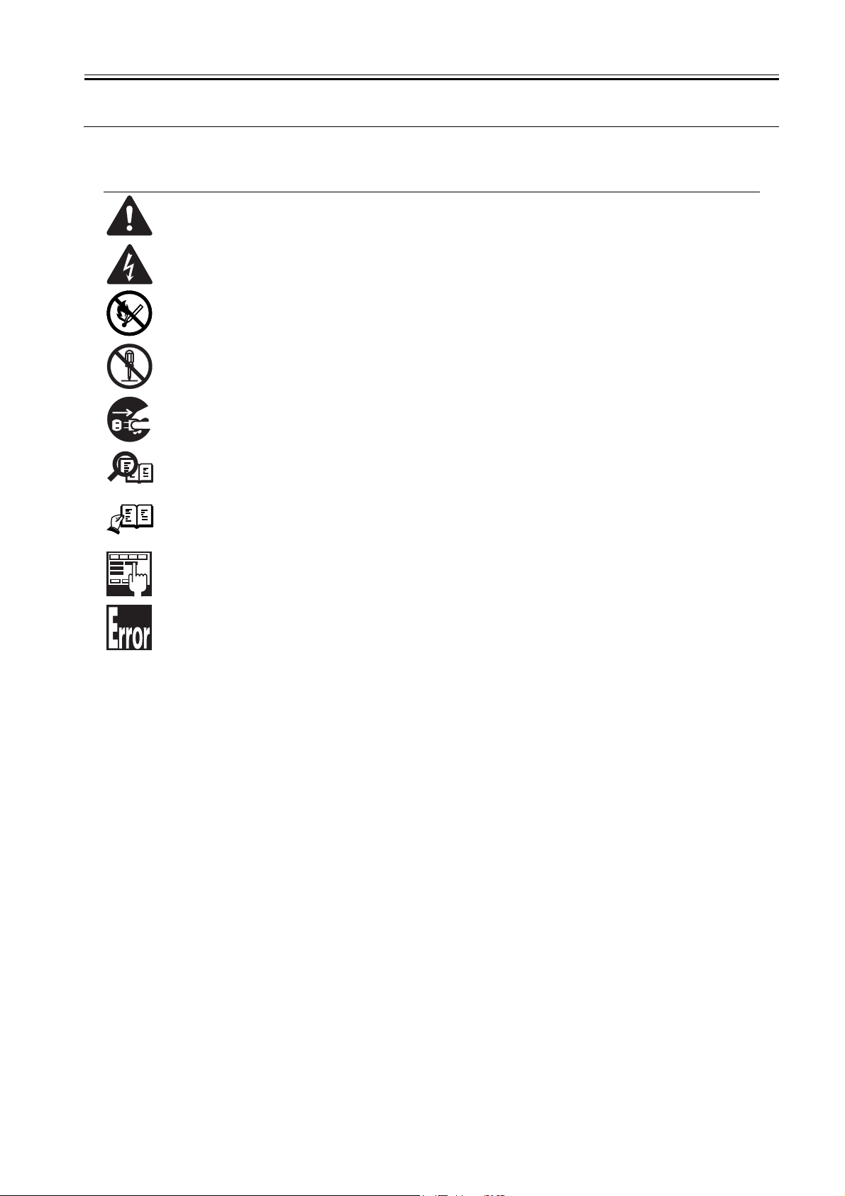
Symbols Used
This documentation uses the following symbols to indicate special information:
Symbol Description
Indicates an item of a non-specific nature, possibly classified as Note, Caution, or Warning.
Indicates an item requiring care to avoid electric shocks.
Indicates an item requiring care to avoid combustion (fire).
Indicates an item prohibiting disassembly to avoid electric shocks or problems.
Indicates an item requiring disconnection of the power plug from the electric outlet.
Indicates an item intended to provide notes assisting the understanding of the topic in question.
Memo
Introduction
REF.
Indicates an item of reference assisting the understanding of the topic in question.
Provides a description of a service mode.
Provides a description of the nature of an error indication.
Page 5

Introduction
The following rules apply throughout this Service Manual:
1. Each chapter contains sections explaining the purpose of specific functions and the relationship between electrical and mechanical systems with reference to the timing of operation.
In the diagrams, represents the path of mechanical drive; where a signal name accompanies the symbol , the arrow indicates the
direction of the electric signal.
The expression "turn on the power" means flipping on the power switch, closing the front door, and closing the delivery unit door, which results in
supplying the machine with power.
2. In the digital circuits, '1'is used to indicate that the voltage level of a given signal is "High", while '0' is used to indicate "Low".(The voltage value, however, differs from circuit to circuit.) In addition, the asterisk (*) as in "DRMD*" indicates that the DRMD signal goes on when '0'.
In practically all cases, the internal mechanisms of a microprocessor cannot be checked in the field. Therefore, the operations of the microprocessors
used in the machines are not discussed: they are explained in terms of from sensors to the input of the DC controller PCB and from the output of the
DC controller PCB to the loads.
The descriptions in this Service Manual are subject to change without notice for product improvement or other purposes, and major changes will be communicated in the form of Service Information bulletins.
All service persons are expected to have a good understanding of the contents of this Service Manual and all relevant Service Information bulletins and be
able to identify and isolate faults in the machine."
Page 6

Page 7

Contents
Contents
Chapter 1 Specifications
1.1 Product composition....................................................................................................................................... 1- 1
1.1.1 Operating conditions of Hardware (LCD)............................................................................................. 1- 1
1.2 Specifications .................................................................................................................................................. 1- 2
1.2.1 Specifications of UFRII LT Printer Driver ............................................................................................ 1- 2
1.2.2 Specifications ........................................................................................................................................... 1- 5
Chapter 2 Functions
2.1 New Function................................................................................................................................................... 2- 1
2.1.1 Special function to thin line .................................................................................................................... 2- 1
2.1.2 Device setting (Mac OS X)..................................................................................................................... 2- 2
Chapter 3 Installation
3.1 Checking components ................................................................................................................................... 3- 1
3.1.1 Checking the Contents............................................................................................................................ 3- 1
3.2 Installation procedure..................................................................................................................................... 3- 1
3.2.1 Mounting to the iR Machine ................................................................................................................... 3- 1
3.2.2 Checking the Connection ....................................................................................................................... 3- 4
Page 8

Page 9

Chapter 1 Specifications
Page 10

Page 11

Contents
Contents
1.1 Product composition........................................................................................................................................... 1-1
1.1.1 Operating conditions of Hardware (LCD)................................................................................................... 1-1
1.2 Specifications ..................................................................................................................................................... 1-2
1.2.1 Specifications of UFRII LT Printer Driver ................................................................................................ 1-2
1.2.2 Specifications .............................................................................................................................................. 1-5
Page 12

Page 13

1.1 Product composition
Chapter 1
1.1.1 Operating conditions of Hardware (LCD)
-A resolution of UFRII LT can be set to either 600 dpi (128MB) or 600/1200dpi (256MB) depending on the memory installed. The 256MB RAM bundled with the
PCL_PRINTER_KIT-J1kit is the same one as a 256MB RAM, which is set as iR 256MB Expansion RAM-D1(0449B001AA).
-License authentication is not necessarily conducted at the time of installation.
-In order to use UFRII LT, the Network board supplied with the kit is necessary.
-PCL Printer Kit-J1 should be installed after installing UFRII LT.
Main body configuration and Accessories
In iR2020/2016, some models that have not been provided with extended capabilities at shipment are either the ones that system accessories can be added or the
others that they cannot be done.
0011-1136
The followings are the models that accessories cannot be added.
T-1-1
Non Upgradeable Model
Merchandise control name iR2020J
Point of destination CSPL CH CLA EUR/Saudi
Product number of main
body
UFRII LT Printer kit-J2
Network Board
PCL Printer kit-J1
256MB RAM
*TBD: to be determied
The followings are the models that accessories can be added.
iR2016(Upgradeable Model)
16ppm Copy Copy/Print
Merchandise control name iR2016
Point of destination EUR/Saudi
Product number of main body F18-8991 F18-8961 TBD F18-8932 F18-8941 F18-8960 F18-8901
UFRII LT Printer kit-J2
Network Board
PCL Printer kit-J1 Option
256MB RAM* Not Available Not Available Option
230V
F18-8945 F18-8965 F18-8939 F18-8999 F18-8949 F18-8969 *TBD
EUR 230V
FRAN
GER
ITA
UK
iR2020J CN
220V
iR2016
AU 230V
CA KR USA
Option
iR2016J
120V
iR2016
KR 220V
T-1-2
iR2016 EUR
230V
FRN
GER
ITA
UK
Not Available
iR2016
120V
Canada
CLA
iR2016J
230V
CSPL
CLA
iR2016 230V iR2016
CHK
CSPL
CLA
iR2016J CN
220V
CH KR
Standard
iR2016J KR
220V
CN 220V
CH TW
iR2016
TW 120V
The 256MB RAM bundled with the PCL_PRINTER_KIT-J1kit is the same one as a 256MB RAM, which is set as iR 256MB Expansion RAM-D1(0449B001AA).
1-1
Page 14

Chapter 1
iR2020(Upgradeable Model)
T-1-3
20ppm Copy Copy/Print
Merchandise control
name
Point of destination EUR/Saudi
Product number of main
body
UFRII LT Printer kit-J2
Network Board
PCL Printer kit-J1 Option
256MB RAM* Not Available Not Available Option
iR2020
EUR 230V
FRAN
GER
ITA
UK
F18-8993 F18-8963 TBD F18-8934 F18-8943 F18-8968 F18-8903
iR2020
AU 230V
CA KR USA
Option
iR2020 KR
220V
iR2020
120V
Canada
CLA
iR2020 230V iR2020
CHK
CSPL
CLA
CN 220V
CH TW
Standard
iR2020
TW 120V
The 256MB RAM bundled with the PCL_PRINTER_KIT-J1kit is the same one as a 256MB RAM, which is set as iR 256MB Expansion RAM-D1(0449B001AA).
1.2 Specifications
1.2.1 Specifications of UFRII LT Printer Driver
1. Support Environment (OS/Software)
Microsoft Windows 2000 Professional/Server
Microsoft Windows XP Home Edition/Professional Edition
Microsoft Windows Server 2003 (32bit edition)
Microsoft Windows 98 (Second Edition)
Microsoft Windows Millennium Edition
2. Font Handling
Device fonts are not used as the printing uses the UFR II driver.
GDI raster fonts cannot be used - e.g.
One Byte - Courier, MS Sans Serif, and MS Serif.
Two Byte - FixedSys, System, Small Fonts, Terminal
GDI vector fonts can be used - e.g.
One Byte - Modern, Roman, and Script.
TureType fonts can be used - e.g.
One Byte - Arial, Courier New, Symbol, Times New Roman
Note:
Each font becomes usable by the font addition to Windows.
3. Paper Size
Standard-size types of paper to be supported are described below.
Paper Name
A3 297.0 420.0
B4 257.0 364.0
A4 210.0 297.0
B5 182.0 257.0
A5 148.5 210.0
11 x 17 279.4 431.8
LEGAL 215.9 355.6
LETTER 215.9 279.4
STATEMENT 139.7 215.9
EXECUTIVE 184.2 266.7
COM 10 104.7 241.3
MONARCH 98.4 190.5
C5 ISO 162.0 229.0
B5 ISO 176.0 250.0
DL 110.0 220.0
4.Non-default paper
User-defined paper iR2020/2016
minimum 95.0 x 148.0 mm
maximum 297.0 x 431.8 mm
Area-Specific Paper Sizes:
In addition to default paper sizes (A4/LTR) and user-defined paper sizes, the printer driver supports area-specific paper sizes (e.g., Officio), and it handles these
area-specific paper sizes as user-defined paper sizes, requiring the user to register them in advance of use. To do so, see the instructions on registering user-defined
paper sizes for individual operating systems.
When an area-specific paper size is manually set up under [Form to Tray Assignment] of the driver UI, or if the size obtained by running dynamic configuration
happens to be an area-specific paper size, the driver operates in the corresponding mode. After performing all associated internal operations, the driver runs a check
of area-specific paper sizes stored as user defined paper sizes, and handles any matching paper as a default paper size (special paper ID) instead of as a user-defined
paper size. Moreover, the driver permits registration of multiple area-specific paper sizes, treating them as a separate paper group. The driver UI handles them using
specifications designed for LTR paper, permitting the use of finisher functions, which were previously offered for user-defined paper sizes (except the use of the
T-1-4
Paper Size (mm)
Width length
T-1-5
0011-1138
1-2
Page 15

Chapter 1
middle binding function). Although it will permit all settings, the printer unit may ignore some of the settings. (The printer driver will simply ignore them, not
issuing conflicts.)
UFRII LT
Effective print area
Paper size Dimensions(mm)
Oficio OFI 216.0 317.0
Ecuadorian Oficio E_OFI 220.0 320.0
Bolivia Oficio B_OFI 216.0 355.0
Mexican Oficio M_OFI 216.0 341.0
Argentina Oficio A_OFI 220.0 340.0
Folio FOLIO 210.0 330.0
Argentina Letter A_LTR 220.0 280.0
Goverment Letter G_LTR 203.0 267.0
Goverment Legal G_LGL 203.0 330.0
Australian Foolscap A_FLSP 203.0 337.0
Foolscap FLSP 206.0 330.0
8K 8K 297.0 390.0
16K 16K 195.0 270.0
Effective print area(mm) End of Papaer(mm)
Main scaning Sub scaning Main scaning Sub scaning
Minimum 85.00 138.00 5.00 5.00
Maximum 287.00 421.80 5.00 5.00
T-1-6
Width Height
T-1-7
The size of the printable area is the one that excludes a margin of 10mm from the edge of envelope.
0mm mode
T-1-8
0mm Mode(mm)
Effective print area End of Papaer
Main scaning
Minimum 89.00 142.00 3.00 Top:3.00,Bottom3.00
Maximum 291.00 425.80 3.00 Top:3.00,Bottom3.00
UFRII LT as a printing description language does not have a concept of printable area.
The printable area from the edge of the paper is decided depending on the limitations of the hardware of the iR main body.
Sub
scaning
Main scaning Sub scaning
F-1-1
1-3
Page 16

Chapter 1
F-1-2
5. Supported Paper Types
Paper Type Paper Size
PLAIN
COLOR
RECYCLED
HEAVY
BOND
LABELS
OHP A4, LTR
3-hole Punch LTR/LTRR
Envelope COM10, MONARCH, C5ISO, B5ISO, DL
T-1-9
A3, B4, A4/A4R, B5/B5R, A5/A5R, 11x17, LGL, LTR/LTRR, STMT/STMTR, EXEC, Oficio, User-defined paper
A3, B4, A4/A4R, B5/B5R, A5/A5R, 11x17, LGL, LTR/LTRR, STMT/STMTR, EXEC, User-defined paper
1-4
Page 17

Chapter 1
6. Finishing
T-1-10
Finisher Shift Staple
None N/A N/A
Inner 2way Tray N/A N/A
Finisher-U1 OK OK
N/A : not available.
7. Resolution
Fine (600dpi) / Super fine (1200dpi)
Super fine (1200dpi) can be selected only when the installed memory is 256MB.
1.2.2 Specifications
UFRII LT is compatible with both of new OS and the existing ones.
It is compatible with Windows98 (Second edition) by using the image mode processing of all internal ones of UFR II.
It is also compatible with Mac OS X, new operating system.
Specification
Data processing 600dpi(128MB RAM)/1200dpi(256MB RAM)
Effective printable area main scanning:5.0mm
Supported
operating systems
sub scanning:5.0mm
Windows 98(Second Edition)
Windows millennium Edition
Windows 2000 Professional/Server/Advanced Server
Windows XP Home Edition/Professional Edition
Windows Server 2003 Standard Edition/Enterprise Edition
(32 bit Edition)
Mac OS X v10.1.5 - V10.3.8
T-1-11
UFRII LT
0011-1139
1-5
Page 18

Page 19

Chapter 2 Functions
Page 20

Page 21

Contents
Contents
2.1 New Function ..................................................................................................................................................... 2-1
2.1.1 Special function to thin line......................................................................................................................... 2-1
2.1.2 Device setting (Mac OS X) ......................................................................................................................... 2-2
Page 22

Page 23

2.1 New Function
Chapter 2
2.1.1 Special function to thin line
Special function to thin line
In the process of resolution change from original to printer driver, some of 1 dots may be omitted. In this case, the faulty occurs, for instance, a continuous line is
printed as a dotted line.
Use conditions:
The memory of the iR main body should be upgraded to 256MB in order to select this function.
This function uses a method that 1 dot is drawn as 2 dots by the setting on the printer driver, and that can prevent image losses.
The memory should be set to 256 MB in options on the printer driver.
The resolution in the printing quality on the printer driver should be set to 1200 dpi.
Special function to thin line in the finishing on the printer driver should be selected.
Device Settings > Installed Memory > 256MB
F-2-1
0011-1140
Quality > Details.. > Resolution : 1200dpi
F-2-2
F-2-3
Finishing > Finishing Details.. > Advanced Settings.. > Specical Fine Line Process
2-1
Page 24

Chapter 2
F-2-4
F-2-5
F-2-6
2.1.2 Device setting (Mac OS X)
When printing by using USB connection cable from the PC running on Mac OS X, it is impossible to obtain device information and automatically set the configuration, such as sorter or paper deck, as the iR main body can provide only one-way communication. Printing, therefore, should be done with the button of Device
0011-1141
Settings on the printer driver.
F-2-7
2-2
Page 25

Chapter 3 Installation
Page 26

Page 27

Contents
Contents
3.1 Checking components ........................................................................................................................................ 3-1
3.1.1 Checking the Contents................................................................................................................................. 3-1
3.2 Installation procedure ......................................................................................................................................... 3-1
3.2.1 Mounting to the iR Machine ....................................................................................................................... 3-1
3.2.2 Checking the Connection ............................................................................................................................ 3-4
Page 28

Page 29

3.1 Checking components
Chapter 3
3.1.1 Checking the Contents
[4]
[1]
[5]
[6]
0010-7374
[3][2]
[7]
[8]
F-3-1
[1] LAN cover 1 pc. [6] User Software CD-ROM 1 pc.
[2] LAN PCB 1 pc. [7] User Manual CD-ROM 1 pc.
[3] IP-LAN cable 1 pc. [8] Release Note 1 pc.
[4] Wire saddle 1 pc. [9] Network Quick Start Guide 1 pc.
[5] TP screw (3x8) 8 pc.
3.2 Installation procedure
3.2.1 Mounting to the iR Machine
1) Turn off the main power switch, and disconnect the power plug from the power outlet.
2) Remove the machine's rear cover [1].
- 4 screws [2]
[2]
[9]
0010-7487
3) Cut off the area [2] of the rear cover [1] indicated in the figure using nippers.
[1]
F-3-2
3-1
Page 30

Chapter 3
4) Mount the LAN board [1].
- 4 TP screws (3x8)
[1]
[2]
F-3-3
[2]
[1]
5) Connect the LAN board and the IP board.
- 1 IP-LAN cable [1]
6) Fit the wire saddle (black) [1] in place, and fit the IP-LAN cable [2] in it.
[2]
F-3-4
[1]
F-3-5
3-2
Page 31

7) Mount the LAN cover [1].
- 4 TP screws (3x8) [2]
Chapter 3
[1]
[2]
F-3-6
[2]
[2]
F-3-7
[1]
Points to Note When Attaching the LAN Cover
A grounding wire is fitted to the IP machine's IP PCB and IP cover. When attaching the LAN cover, be sure to remove the screw [1] from the wire, and tighten the
screw over both the wire and the LAN cover [2].
[1]
F-3-8
When mounting the LAN cover [1], take care so that the grounding plate [3] will not be bent by the LAN board [2].
Also, after mounting the cover, check to be sure that the grounding plate is in firm contact with the LAN board.
[2]
3-3
Page 32

Chapter 3
8) Put back the machine's rear cover you removed in step 2).
9) Connect the user's LAN cable to the machine.
[3]
[2]
[1]
F-3-9
F-3-10
10) Connect the power plug to the power outlet, and turn on the main power switch.
3.2.2 Checking the Connection
At the end of the work, go through the following steps to make sure that the machine properly recognizes the presence of the unit:
1) Start service mode.
User Mode key >2 > 8 > User Mode key
[#SSSW] appears.
2) Press [<-] 5 times. When [REPORT] has appeared, press [OK].
3) Press [+>] once. When [REPORT OUTPUT] has appeared, press [OK].
4) Press [+>] 5 times. When [SPEC LIST] has appeared, press [OK].
5) See that a SPEC REPORT is printed out. Check to be sure that 'BDL-IMAGE' is 'ON'.
MEMO:
"SPEC REPORT"
- If 'TOTAL MEMORY' is 128 MB,
be sure 'BDL-IMAGE (600)' is 'ON'.
- If 'TOTAL MEMORY' is 256 MB,
be sure 'BDL-IMAGE (1200)' is 'ON'.
0010-7517
3-4
Page 33

Sep 14 2005
Page 34

 Loading...