

Page 1

Installation Procedure
iR2020/2016 Series
Sep 14 2005
Page 2

Page 3

Application
This manual has been issued by Canon Inc. for qualified persons to learn technical theory, in-
stallation, maintenance, and repair of products. This manual covers all localities where the prod-
ucts are sold. For this reason, there may be information in this manual that does not apply to
your locality.
Corrections
This manual may contain technical inaccuracies or typographical errors due to improvements or
changes in products. When changes occur in applicable products or in the contents of this manual,
Canon will release technical information as the need arises. In the event of major changes in the
contents of this manual over a long or short period, Canon will issue a new edition of this manual.
The following paragraph does not apply to any countries where such provisions are inconsistent
with local law.
Trademarks
The product names and company names used in this manual are the registered trademarks of the
individual companies.
Copyright
This manual is copyrighted with all rights reserved. Under the copyright laws, this manual may
not be copied, reproduced or translated into another language, in whole or in part, without the
written consent of Canon Inc.
COPYRIGHT © 2001 CANON INC.
Printed in Japan
Caution
Use of this manual should be strictly supervised to avoid disclosure of confidential information.
Page 4
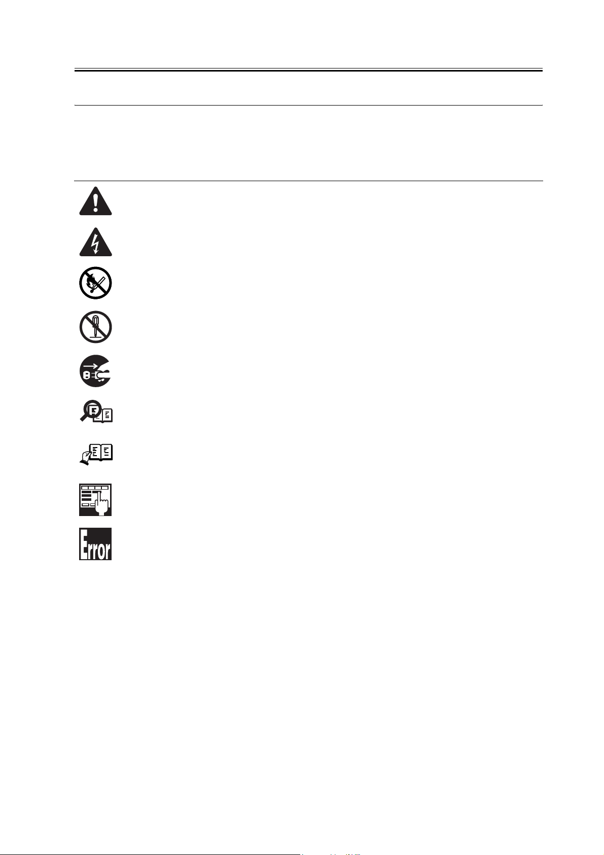
Symbols Used
This documentation uses the following symbols to indicate special information:
Symbol Description
Indicates an item of a non-specific nature, possibly classified as Note, Caution, or Warning.
Indicates an item requiring care to avoid electric shocks.
Indicates an item requiring care to avoid combustion (fire).
Indicates an item prohibiting disassembly to avoid electric shocks or problems.
Introduction
Memo
REF.
Indicates an item requiring disconnection of the power plug from the electric outlet.
Indicates an item intended to provide notes assisting the understanding of the topic in question.
Indicates an item of reference assisting the understanding of the topic in question.
Provides a description of a service mode.
Provides a description of the nature of an error indication.
Page 5

Introduction
The following rules apply throughout this Service Manual:
1. Each chapter contains sections explaining the purpose of specific functions and the rela-
tionship between electrical and mechanical systems with reference to the timing of operation.
In the diagrams, represents the path of mechanical drive; where a signal name accom-
panies the symbol , the arrow indicates the direction of the electric signal.
The expression "turn on the power" means flipping on the power switch, closing the front
door, and closing the delivery unit door, which results in supplying the machine with power.
2. In the digital circuits, '1'is used to indicate that the voltage level of a given signal
is "High", while '0' is used to indicate "Low".(The voltage value, however, differs from
circuit to circuit.) In addition, the asterisk (*) as in "DRMD*" indicates that the DRMD
signal goes on when '0'.
In practically all cases, the internal mechanisms of a microprocessor cannot be checked in
the field. Therefore, the operations of the microprocessors used in the machines are not
discussed: they are explained in terms of from sensors to the input of the DC controller PCB
and from the output of the DC controller PCB to the loads.
The descriptions in this Service Manual are subject to change without notice for product improvement or other purposes, and major changes will be communicated in the form of Service
Information bulletins.
All service persons are expected to have a good understanding of the contents of this Service
Manual and all relevant Service Information bulletins and be able to identify and isolate
faults in the machine."
Page 6

Page 7

Contents
Contents
Chapter 1 Installation Procedure
1.1 Making Pre-Checks ............................................................................................................................................ 2
1.1.1Selecting the Site of Installation ................................................................................................................. 2
1.1.2Before Starting the Work (230V EUR)....................................................................................................... 3
1.2 Unpacking and Installation ................................................................................................................................ 7
1.2.1Unpacking and Removing the Packaging Materials ............................................................................... 7
1.2.2Installing the Drum Unit ............................................................................................................................... 7
1.2.3Installing the Toner Bottle............................................................................................................................ 9
1.2.4Setting the Cassettes ................................................................................................................................. 10
1.2.5Attaching the Ferrite Core ......................................................................................................................... 12
1.2.6Checking the Image Quality...................................................................................................................... 13
1.2.7Setting the Country/Region ....................................................................................................................... 13
1.2.8Setting the Date and Time......................................................................................................................... 13
1.3 Checking the Connection to the Network ..................................................................................................... 15
1.3.1Checking the Network Connection........................................................................................................... 15
1.4 Installing the Card Reader............................................................................................................................... 17
1.4.1Points to Note .............................................................................................................................................. 17
1.4.2Checking the Contents............................................................................................................................... 17
1.4.3Installation Procedure ................................................................................................................................ 17
1.4.4Registering the Card IDs ........................................................................................................................... 22
1.5 Installing the Heater PCB ................................................................................................................................ 24
1.5.1Unpacking and Checking the Contents................................................................................................... 24
1.5.2Preparing the Host Machine ..................................................................................................................... 24
1.5.3Installing the Heater PCB .......................................................................................................................... 25
1.6 Installing the Reader Heater ........................................................................................................................... 29
1.6.1Unpacking and Checking the Contents................................................................................................... 29
1.6.2Installing the Reader Heater Harness ..................................................................................................... 29
1.6.3Removing Reader Components............................................................................................................... 32
1.6.4Removing Parts at the Left of the Reader .............................................................................................. 33
1.6.5Installing the Reader Heater ..................................................................................................................... 34
1.7 Installing the Cassette Heater......................................................................................................................... 38
1.7.1Unpacking and Checking the Contents................................................................................................... 38
1.7.2Preparing the Host Machine ..................................................................................................................... 38
1.7.3Installing the Cassette Heater................................................................................................................... 38
Page 8

Contents
Page 9

Chapter 1 Installation
Procedure
Page 10
Chapter 1
1.1 Making Pre-Checks
1.1.1 Selecting the Site of Installation
0011-1068
iR2016J / iR2016 / iR2020 / / iR2016i / iR2020i
Select the site of installation against the following requirements; if possible, visit the user's before delivery of the
machine:
1) There must be a power outlet properly grounded and rated as indicated (-/+10%) for exclusive use by the machine.
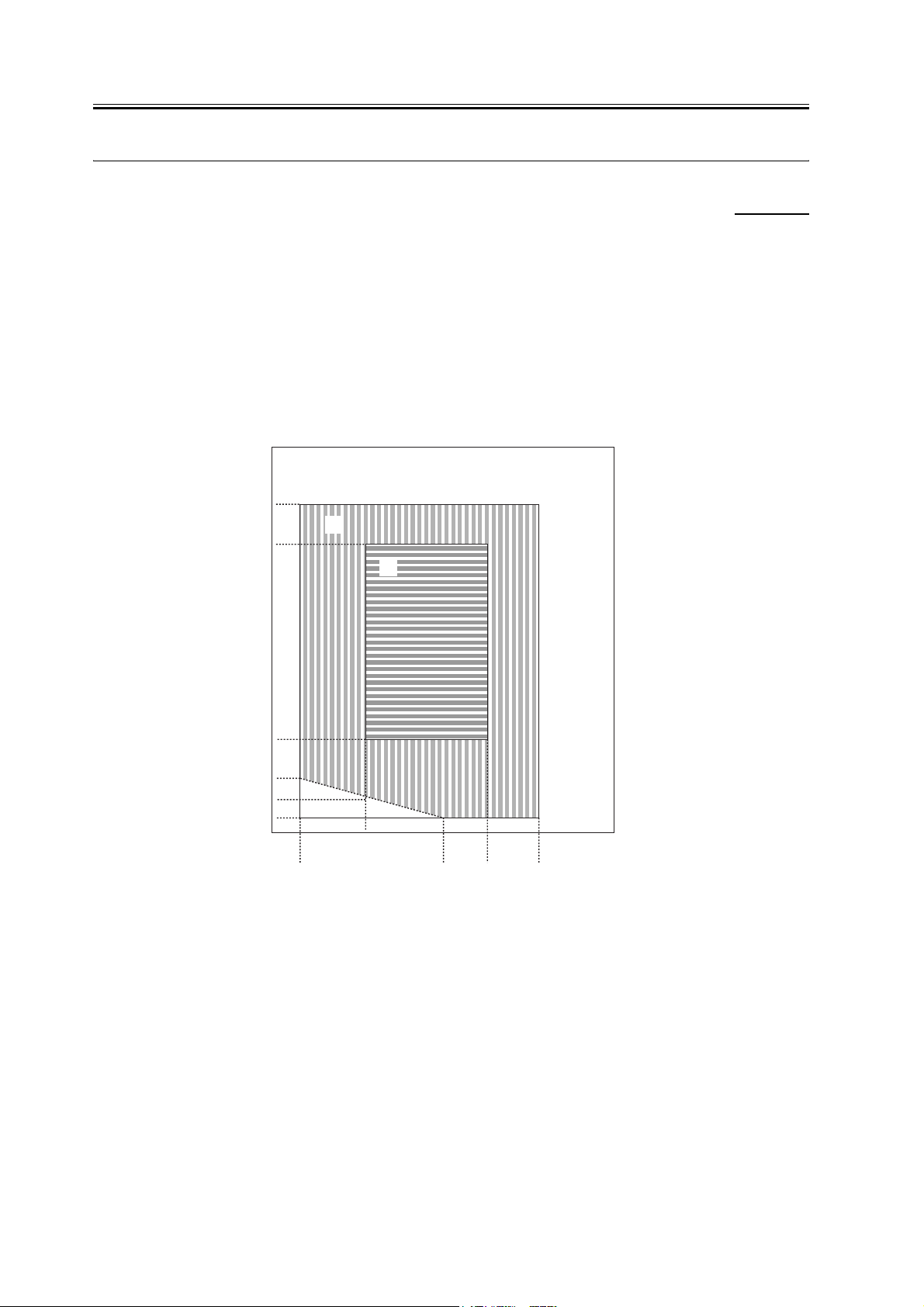
2) The environment of the room must be as indicated in the following diagram, and the machine must not be installed
near a water faucet, water boiler, humidifier, or refrigerator:
(%RH)
100
90
85
75
70
50
[C]
[B]
[A]
25
20
15
10
5
010
7.5 23 27.5 32.5
15 20 25 30 35 40
(degC)
F-1-1
<Environmental zone assured>
[A]: Zone A: Satisfies all the conditions of the standard image quality and paper feed performance.
[B]: Zone B: Inferior to Zone A in terms of the standard image quality and paper feed performance, or may not apply.
[C]: Zone C: Problems associated with safety, malfunctions, or incorrect message display do not occur, but image
quality and paper feed performance are not guaranteed.
3) The machine must not be installed near a source of fire or in an area subject to dust or ammonium gas.
If the area is exposed to direct rays of the sun, provide curtains to the window.
4) The level of ozone generated by the machine will not affect the health of individuals around it. Some, however,
may find its odor unpleasant as while remaining in contact with it for long hours. Be sure that the room is well
2
Page 11
Chapter 1
ventilated.
5) The floor of the machine must be level so that the feet of the machine will remain in contact and the machine will
remain level.
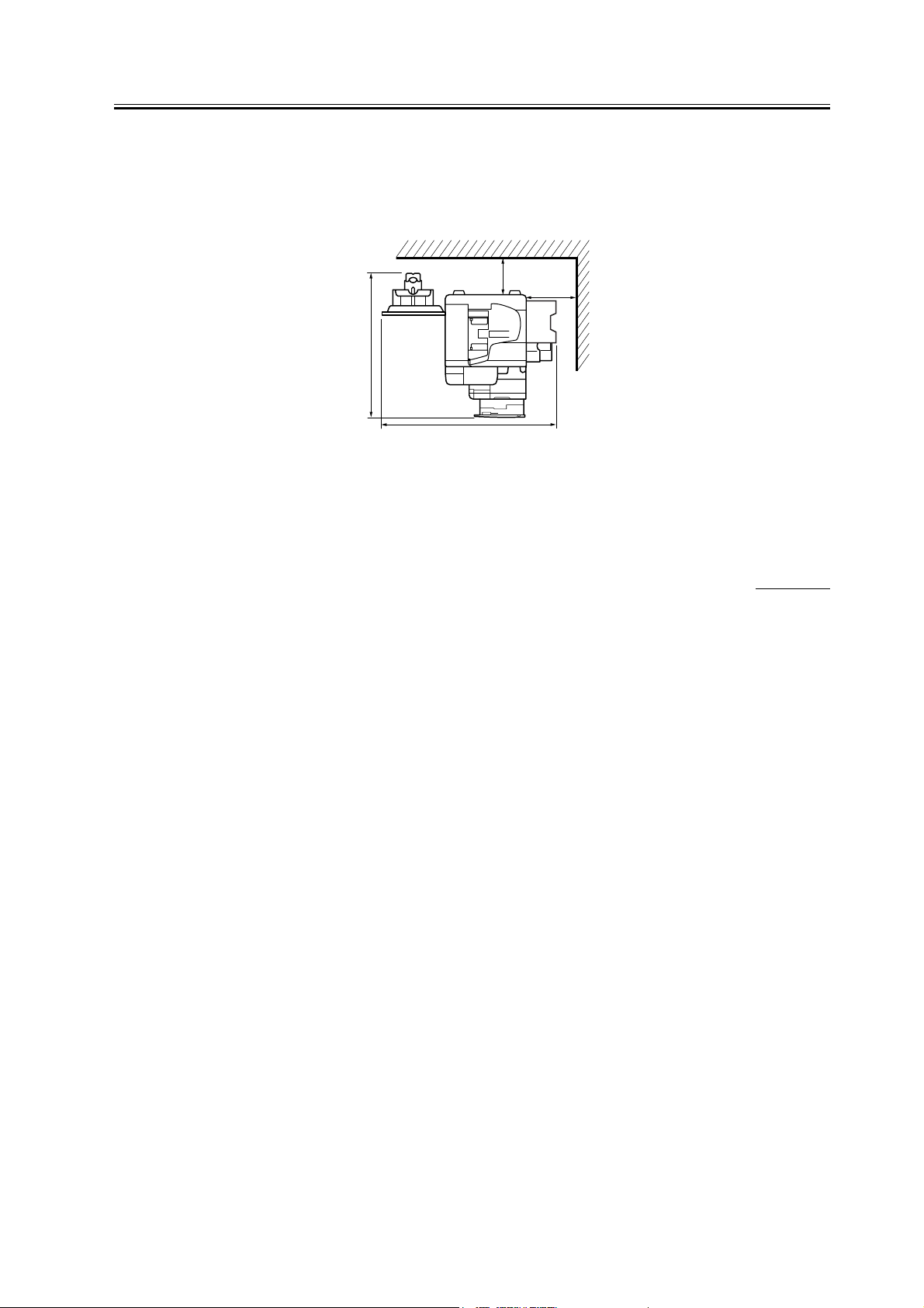
6) The machine must be at least 10 cm away from any wall, permitting unobstructed use.
100 mm min.
100 mm min.
1249 mm
1247 mm
F-1-2
7) The machine must be placed in a well ventilated area. It is important to make sure, however, that the machine is
not near the air vent (for suction) of the room.
1.1.2 Before Starting the Work (230V EUR)
0011-3206
iR2016J / iR2016 / iR2020
1-1 Points to Make Before Installation
Be sure to go through the following before starting the work:
1) If you are installing the machine after moving it from a cold to warm location, be sure to leave the machine unpacked for at least 2 hours so that the machine is fully used to the site temperature, thus avoiding image faults
caused by condensation. (The term "condensation" refers to the formation of droplets of water on the surface of a
metal object brought in from a cold to warm place, i.e., as the result of the rapid cooling of the moisture (vapor)
around the object.)
2) The machine weighs a maximum of about 46 kg. Be sure to work in a group of 2 persons when lifting it.
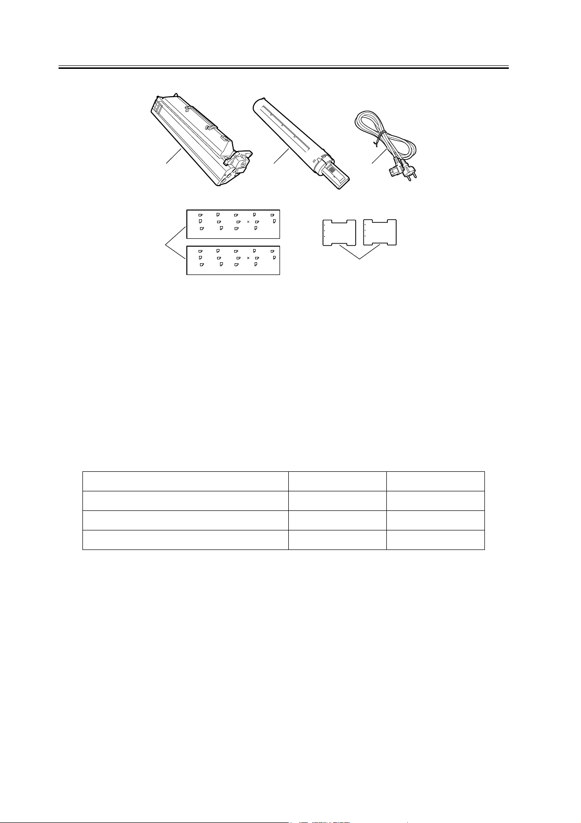
1-2 Checking the Contents
Check to be sure that none of the following contents is missing:
3
Page 12
Chapter 1
[4]
[1]
LTR
LTR
A3
B5
A3
B5
A4
B5
STMT
A4
B5
STMT
LGL
LGL
A4
8K
A4
8K
[2] [3]
B4
A5
LTR
11 17
16K
B4
A5
LTR
11 17
16K
F-1-3
[1] Drum unit ---1 [4] Cassette size label ---2(1) (*1)
[2] Black toner ---1 [5] Caution sheet ---2(1) (*1)
[3] Power cable ---1
*1: iR2020: 2 pc., iR2016/iR2016J: 1 pc.
Check the documentation and CD against the following table:
Set the size detector lever to the
new paper size.
Placer I’indicateur de format sur
le nouveau format.
Bitte stellen Sie den Hebel zum
Erkennen des Papierformats auf
das neue Format ein.
FU5-xxxx
[5]
Set the size detector lever to the
new paper size.
Placer I’indicateur de format sur
le nouveau format.
Bitte stellen Sie den Hebel zum
Erkennen des Papierformats auf
das neue Format ein.
FU5-xxxx
Documentation and CD iR2020/iR2016 iR2016J
Operators manual: User's Guide Yes Yes
Operators manual: Easy Operation Guide No Yes
Operators manual CD-ROM Yes Yes
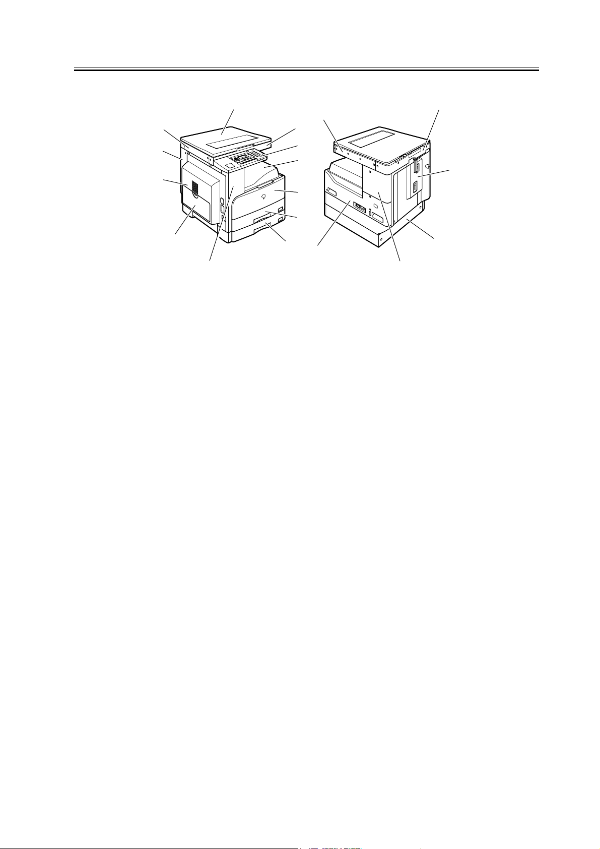
1-3 Names of Parts
T-1-1
4
Page 13
Chapter 1
[1]
[12]
[11]
[10]
[9]
[8] [17]
[7]
[13]
[2]
[3]
[4]
[5]
[6]
[18]
F-1-4
T-1-2
[1] Copyboard cover [10] Left door
[2] Reader front cover [11] Left cover (rear)
[3] Control panel [12] Reader left cover
[4] Delivery tray [13] Reader right cover
[14]
[15]
[16]
[5] Front cover [14] Reader erar cover
[6] Cassette 1 [15] Rear cover
[7] Cassette 2 (*2) [16] Cassette rear cover (*2)
[8] Left cover (front) [17] Right cover (upper)
[9] Manual feed tray [18] Right cover (lower)
*2. iR2020 only
5
Page 14

Chapter 1
6
Page 15
Chapter 1
1.2 Unpacking and Instal-
lation
1.2.1 Unpacking and
Removing the Packag-
ing Materials
iR2016J / iR2016 / iR2020 / / iR2016i / iR2020i
1) Unpack the machine and remove vinyl, cushioning
materials, and tape.
2) Hold the handles [1] of the machine together with
one or more persons and take it out.
The maximum weight of this machine is approximately 46kg. Two or more persons are required to lift the
machine.
0011-1070
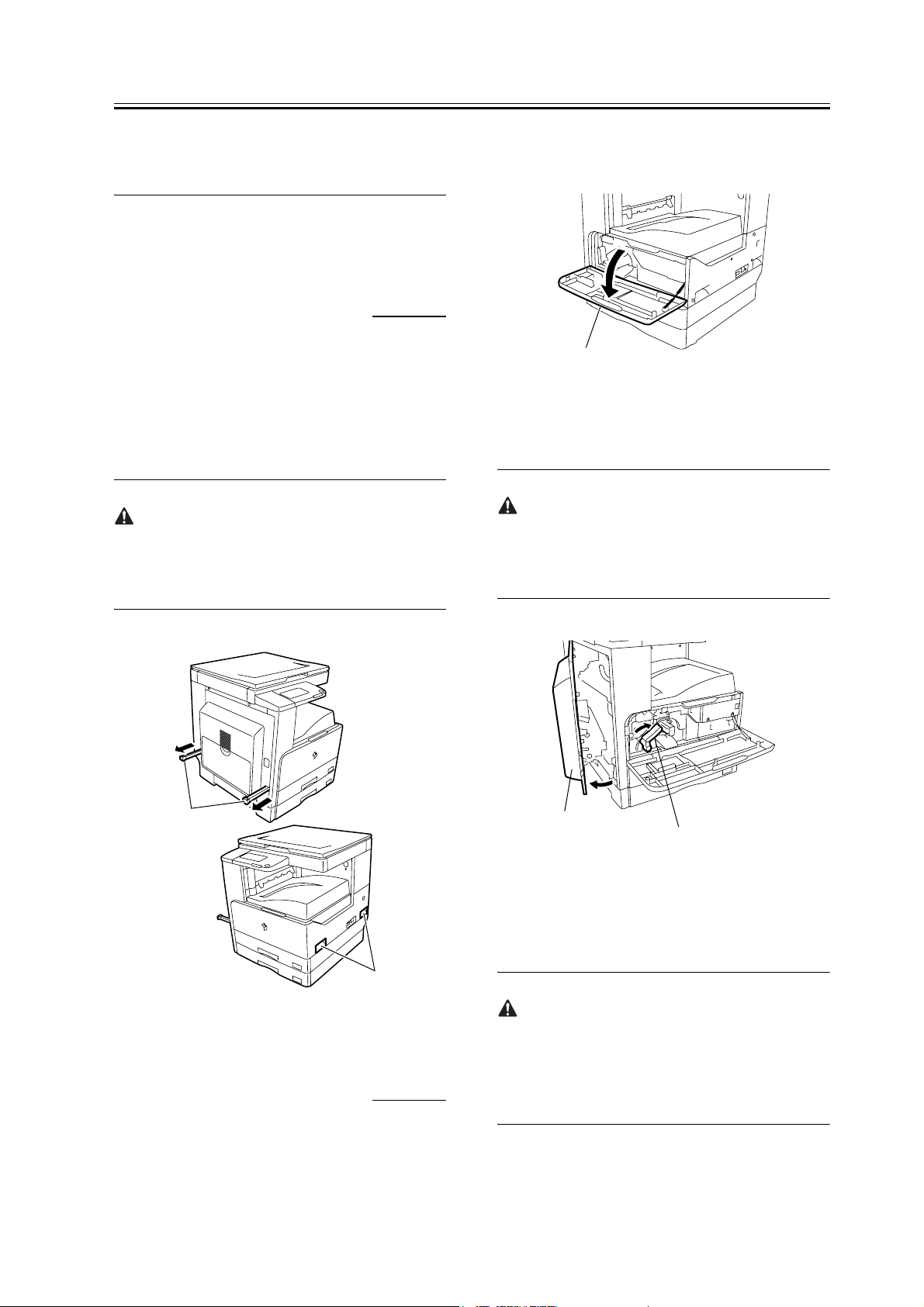
1) Open the front cover [1] of the iR body.
[1]
F-1-6
2) Turn the developer pressure release lever [1] clockwise, and then open the left door [2] until it stops.
The left door must be opened fully to prevent the drum
from being damaged while it is inserted into the drum
unit.
[1]
[1]
F-1-5
1.2.2 Installing the Drum
Unit
iR2016J / iR2016 / iR2020 / / iR2016i / iR2020i
0011-1071
[2]
[1]
F-1-7
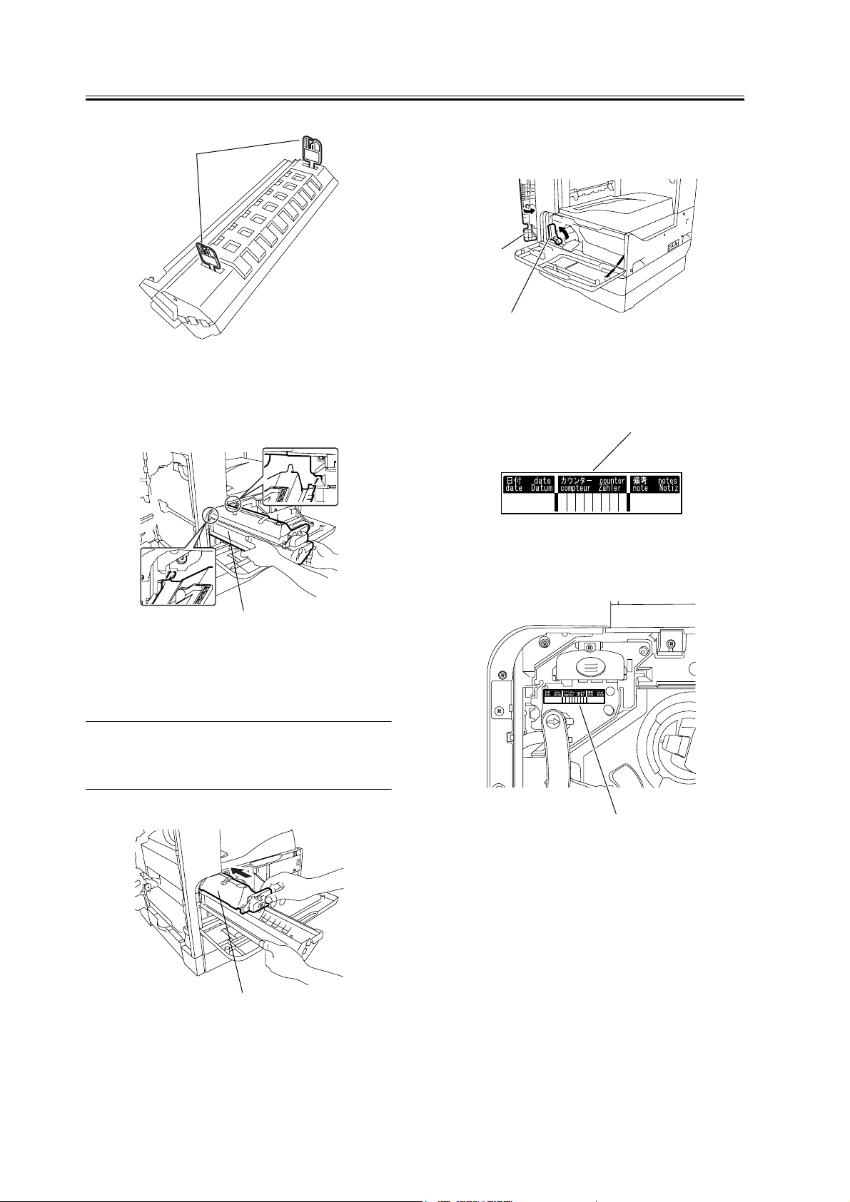
3) Open the packaging bag of the new drum unit, take
the new drum out of it, and then remove packing
tape.
The drum unit for Asia/Oceania is provided with pressure release hooks [1]. Remove them. Drum units for
other regions are not provided with the pressure release hooks.
7
Page 16
Chapter 1
[1]
F-1-8
6) Turn the developer pressure release lever [1] counterclockwise, and then close the left door [2].
[2]
[1]
F-1-11
4) Holding the protective cover [1] of the new drum
unit, place the drum unit against the iR body.
[1]
F-1-9
5) While holding the protective cover, insert the new
drum unit [1] into the iR body.
MEMO:
The protective cover will not be reused.
7) Enter the date in the drum counter label [1].
[1]
F-1-12
8) Affix the drum counter label [1] on the drum unit.
[1]
F-1-13
9) Close the front cover [1].
[1]
F-1-10
8
Page 17

[1]
F-1-14
Chapter 1
[1]
F-1-16
1.2.3 Installing the Toner
Bottle
iR2016J / iR2016 / iR2020 / / iR2016i / iR2020i
If the machine is installed in a low-temperature, lowhumidity place, the image density may be slightly
lower than usual on the first approx. 100 sheets printed after installation of the machine.
When installing the machine in a low-temperature,
low-humidity environment, perform the steps mentioned in <Going through the Developer Idling
Mode> (provided after step 6 in this section) before
installing the toner bottle.
1) Shake the toner bottle 5-6 times.
0011-1072
3) Insert the toner bottle.
F-1-17
4) While holding the toner bottle, pull the seal [1] to
remove it.
F-1-15
2) Open the front cover [1].
[1]
F-1-18
5) Turn the toner cartridge in the direction of the arrow until it stops.
9
Page 18

Chapter 1
6) Close the front cover.
F-1-19
5) Select "#PRINT" using the + or - key, and then
press the OK key.
6) Select "#PRINT SW" using the + or - key, and then
press the OK key. Confirm that the following message is displayed:
Message: #PRINT SW 001 00000000
7) Press the following keys and confirm the message:
# key > 1 key >1 key
Message: #PRINT SW 011 00000000
8) Position the cursor to Bit-1 (second from right) using the + or - key, and press the 1 key, and then confirm the following message:
Message: #PRINT SW 011 0000001
9) Press the OK key. Confirm that "SW 011" changes
to "SW 012".
Message: #PRINT SW 012 00000000
10) Press the Reset key to exit the service mode.
11) Close the front cover. The machine will run in the
developer idling mode for about 1 minute.
12) When the machine stops, the idling mode ends.
Install, the toner cartridge following the above-men-
tioned procedure.
0
F-1-20
<Going through the Developer Idling Mode>
When installing the machine in a low-temperature,
low-humidity environment, go through the developer
idling mode before installing the toner bottle
to prevent the density from becoming low on the first
approx. 100 sheets.
1) Plug the power cord into the outlet.
2) Open the front cover.
3) With the front cover open, turn on the main power
switch.
4) When a message appears on the control panel display, press the following keys to enter the service
mode:
Additional functions key > 2 key > 8 key > Additional functions key
in order
1.2.4 Setting the Cas-
settes
iR2016J / iR2016 / iR2020 / / iR2016i / iR2020i
1) Holding the knob [1] at the center of the cassette,
draw out the cassette [2] until it stops.
0011-1073
10
Page 19

[2]
[1]
F-1-21
2) Remove the wire [1] securing the inner plate of the
cassette.
[1]
Chapter 1
4) Turn the lever [1] of the paper front guide counterclockwise to release it. Slide the paper front guide
[2] to fit to the size of the paper to be used, and then
turn the lever clockwise to lock it.
U2
U3
STMT
U1
LTR
LTR
LGL
B5
11 17
B5
A5
B4
A4
A4
A3
[2]
[1]
F-1-24
5) Turn the paper trailing edge registration plate [1] to
the left to remove it. Re-attach it to fit to the size of
the paper to be loaded.
F-1-22
3) Press the "PUSH DOWN" mark [1] on the inner
plate to lock it into the cassette.
PUSH DOWN
PUSH DOWN
[1]
F-1-25
6) Slide the paper size detection lever [1] to fit to the
paper size.
[1]
F-1-23
11
Page 20

Chapter 1
[1]
F-1-26
9) Align the left, right, and leading edges of sheets and
load the stack of paper in the cassette. Make sure
that the paper is below the claws of the cassette.
MEMO:
Inserting the cassette into the iR body with the inner
plate locked into the cassette will unlock the inner
plate automatically. If the inner plate is not locked,
press the "PUSH DOWN" mark [1] on the inner plate
to lock it into the cassette and then load paper.
7) Affix the cassette size label [1] to the paper size indication plate [2].
A4
[1]
F-1-27
8) Affix the caution sheet printed in an appropriate
language.
[2]
[1]
[2]
F-1-29
10) Holding the knob at the center of the cassette, insert the cassette in the iR body until it stops.
1.2.5 Attaching the Fer-
rite Core
iR2016 / iR2020 / iR2016i / iR2020i
0011-1523
12
(iR2020/iR2016 only for North America, Latin
America, and Asia)
1) Attach the ferrite core [1] to the USB cable [2].
To suppress noise, attach the ferrite core as close as
possible to the USB port of the iR body.
[1]
F-1-28
Page 21

[1]
[2]
Chapter 1
- Check whether abnormal sound is heard.
- Check the printed images at all preset magnifications.
- Check whether the document is copied normally on
the specified number of sheets.
1.2.7 Setting the Country/
F-1-30
1.2.6 Checking the Image
Quality
iR2016J / iR2016 / iR2020 / / iR2016i / iR2020i
1) Plug the power cord into the outlet, and then turn on
the main power switch [2].
Supply of toner will start after the initial rotation.
After a few minutes, supply of toner finishes and
the machine stops automatically.
Use the specified power supply (rated voltage -/+10%
and rated current).
0011-1075
Region
iR2016J / iR2016 / iR2020 / / iR2016i / iR2020i
1) Press the following keys to display the service
mode screen:
Additional Functions Key > 2 Key > 8 Key > Additional Functions Key
2) Select "# CLEAR" using the + or - key, and then
press the OK key.
3) Select "TYPE" using the + or - key, and then press
the OK key.
4) Using the + or - key, select the country/region type
that conforms to the communication standard used
in the country/region where the machine is used.
5) Press the OK key. When "Please Wait" disappears,
the selected country/region type takes effect.
0011-1077
1.2.8 Setting the Date
and Time
iR2016J / iR2016 / iR2020 / / iR2016i / iR2020i
0011-1078
[1]
[2]
F-1-31
2) Place a document on the document glass, take a
copy of it by supplying paper from the cassette or
manual feed tray, and check the printed image. Also
perform the following checks:
1) Press the additional functions keys to display the
user mode screen.
2) Select "4. TIMER SETTINGS" using the + or - key,
and then press the OK key.
3) Select "1. DATE&TIME SETTING" using the + or
- key, and then press the OK key. The set date and
time appears.
4) Enter the current date and time by moving the cursor to the characters you want to enter with the +
and - keys.
5) Press the OK key to allow the entered date and time
to take effect.
13
Page 22

Chapter 1
14
Page 23

1.3 Checking the Connection to the Network
1.3.1 Checking the Net-
Chapter 1
work Connection
iR2016 / iR2020 / iR2016i / iR2020i
If the machine supports a network feature, check the
network connection following the procedure below.
1) Press the following keys to display the service
mode screen:
Additional Functions Key > 2 Key > 8 Key > Additional Functions Key
2) Select "# REPORT" using the + or - key, and then
press the OK key.
3) Select "REPORT OUTPUT" using the + or - key,
and then press the OK key.
4) Select "SPEC LIST" using the + or - key, and then
press the OK key.
5) When "SPEC REPORT" is displayed, check that
"BDL-IMAGE" is set to ON.
MEMO:
"SPEC REPORT"
- TOTAL MEMORY: 128MB
BDL-IMAGE (600) must be set to ON.
- TOTAL MEMORY: 256MB
BDL-IMAGE (1200) must be set to ON.
0011-1079
6) Contact the system administrator of the customer to
make network settings.
15
Page 24

Chapter 1
16
Page 25

1.4 Installing the Card
Reader
1.4.1 Points to Note
0011-1080
Chapter 1
The repeating harness, TP screw (M3x12), and
toothed washer are not used.
iR2016J / iR2016 / iR2020 / / iR2016i / iR2020i
When installing the card reader, the card reader attachment-D1 is required.
1.4.2 Checking the Con-
tents
iR2016J / iR2016 / iR2020 / / iR2016i / iR2020i
<Card reader-E1>
[1]
[2]
0011-1081
[3]
<Card reader attachment-D1>
[2]
F-1-33
F-1-32
[1] Card reader-E1 1 pc.
[2] TP screw (M3x12) 1 pc.
[3] Toothed washer 1 pc.
[4] Repeating harness A 1 pc.
[4]
[1] Card reader mount 1 pc.
[2] Card reader cover 1 pc.
[3] Harness cover (base + lid) 3 pcs.
[4] Repeating harness B 1 pc.
[5] Edge saddle 1 pc.
[6] TP screw 2 pcs.
[7] Binding screw (M4x6) 4 pcs.
1.4.3 Installation Proce-
dure
iR2016J / iR2016 / iR2020 / / iR2016i / iR2020i
1) Turn off the main power switch [1] of the host ma-
0011-1082
17
Page 26

Chapter 1
chine and disconnect the power plug [2] from the
outlet.
[2]
[1]
F-1-34
2) Remove the four screws, and then detach the rear
cover [1].
and then separate the card reader [3] from the card
reader mount [2].
[1]
[2]
[3]
F-1-37
When removing the harness [1] through the opening
in the card reader mount, take care not to cut or damage it.
[1]
F-1-35
3) Remove the screw [1] from the card reader.
MEMO:
The removed screw will be used later.
[1]
F-1-36
4) Remove the screw [1] securing the ground cable,
[1]
F-1-38
MEMO:
The removed card reader mount is no longer necessary.
5) Insert the card reader [2] harness and ground cable
into the hole in the supplied card reader mount [1].
Using the screw [3] removed in step 1, secure the
card reader to the card reader mount.
18
Page 27

When inserting the card reader [2] harness and ground
cable, take care not to cut or damage them.
Chapter 1
MEMO:
The removed shorting connector is no longer necessary.
[3]
[2]
[1]
F-1-39
6) Using the supplied binding screw (M4x6) [1], connect the ground cable to the reader mount. Attach
the supplied edge saddle [3] to the card reader
mount.
[3]
[2]
[1]
[4]
[3]
[2]
[5]
F-1-41
8) Secure the repeating harness B [1] with the wire
saddle [2].
[1]
[2]
[1]
F-1-40
7) Connect the connector [1] of the supplied repeating
harness B to the connector [2] on the card reader.
Using the supplied binding screw (M4x6), secure
the repeating harness B clamp [4]. Disconnect the
shorting connector [5].
If the shorting connector [5] is not disconnected, a
malfunction or error can result. Therefore, the shorting connector must be disconnected.
F-1-42
9) Remove the two blind seals [1] from the reader left
cover.
19
Page 28

Chapter 1
[1]
F-1-43
10) Using the two supplied TP screws (M4x16), attach the card reader to the reader.
When tightening the screws, take care not to damage
the repeating harness B.
[1]
F-1-44
[1]
F-1-45
Route the repeating wire B [1] as shown below.
[1]
F-1-46
12) Using the supplied binding screw (M4x6), secure
the card reader cover [2].
11) Slide the card reader cover [1] to attach it to the
card reader mount.
20
[2]
[1]
F-1-47
13) Affix the two supplied harness covers (bases) at
the right rear of the machine with it aligned with the
bottom line of the reader.
Page 29

Chapter 1
[1]
F-1-48
14) Affix the supplied harness cover (base) [1] at the
back of the machine with it aligned with the bottom
line of the reader.
[1]
[1][2]
F-1-51
17) Using the three harness covers (lids) [2], secure
the repeating harness B [1] to the harness covers
(bases).
[2]
F-1-49
15) Connect the connector of the repeating harness B
[1] to the connector J317 [2] on the image processor
PCB.
[2]
[1]
F-1-50
16) Using the supplied binding screw (M4x6) [1], secure the repeating harness B clamp [2].
[1]
F-1-52
18) Using a nipper, remove the precut portion [1] of
the rear cover as shown below.
21
Page 30

Chapter 1
[1]
F-1-53
19) Attach the rear cover with the repeating harness B
routed through the cut portion of the rear cover.
[1]
F-1-54
1.4.4 Registering the
Card IDs
iR2016J / iR2016 / iR2020 / / iR2016i / iR2020i
0011-1083
1) Plug the power cord [1] into the outlet, and then
turn on the main power switch [2].
[1]
[2]
F-1-55
2) Press the following keys to display the service
mode screen:
Additional Functions Key > 2 Key > 8 Key > Additional Functions Key
3) Select "# ACC" using the + and - key, and then
press the OK key.
4) Select "CARD" using the + and - key, and then
press the OK key.
5) Specify the first ID number of the card ID numbers
to be registered, and then press the OK key.
Sequential Card ID numbers of 100 cards(*) are automatically registered in the department ID, starting
with the specified card ID number.
* When an optional ROM is added, card ID numbers of 1000 cards are registered.
6) Press the Additional Functions key to enter the user
mode.
7) Select "SYSTEM SETTINGS" using the + and key, and then press the OK key.
8) Select "MANAGE DEPT. ID" using the + and key, and then press the OK key.
9) Select "ON" using the + and - key, and then press
the OK key.
10) Turn main power switch off and on again. Check
that "INSERT CARD" appears.
After installing the card reader-E1, register the card
numbers to be used in the service mode of the iR body.
If they are not registered, cards will not be recognized
when inserted.
22
Page 31

Chapter 1
23
Page 32

Chapter 1
]
1.5 Installing the Heater PCB
1.5.1 Unpacking and
Checking the Contents
iR2016J / iR2016 / iR2020 / / iR2016i / iR2020i
1) Prepare the following parts.
[2] [3] [4]
0011-3362
Before installing, make sure the host machine is
turned off. If it is turned on, go through the following:
1. Turn off the main power switch.
2. Disconnect the power cable (from the power outlet).
3. Disconnect the power cable.
[7][6]
F-1-56
[1] Heater PCB unit 1 pc.
[2] Heater switch harness 1 pc.
[3] Cassette heater harness 1 pc.
[4] Heater PCB harness 1 pc.
[5] Clamp 4 pcs.
[6] Edge saddle (small) 2 pcs.
[7] Edge saddle (large) 1 pc.
[8] P screw (M3x8) 2 pcs.
1.5.2 Preparing the Host
Machine
iR2016J / iR2016 / iR2020 / / iR2016i / iR2020i
0011-3363
[8
F-1-57
1) Open the front cover [1].
F-1-58
2) Remove the four screws [1], and then detach the
rear cover [2].
3) Remove the five screws [3]. Remove the two hooks
[4], and then detach the lower-right cover [5].
4) Remove the screw [6], and then detach the upperright cover [7].
24
Page 33

F-1-59
5) Remove the two screws [1], and then the delivery
tray [2].
Chapter 1
F-1-61
1.5.3 Installing the Heater
PCB
iR2016J / iR2016 / iR2020 / / iR2016i / iR2020i
0011-3365
When removing or reinstalling the delivery tray, be
careful not to damage the paper holder [3].
F-1-60
6) Using a nipper or the like, cut out the face plate [2]
(used to install a heater switch) on the lower-right
cover [1].
1) Install the heater PCB unit [2] using the two supplied TP screws (M3x8) [1].
2) Install the heater switch [3] on the right side panel.
Install the heater switch with the OFF position on the
left and the ON position on the right just like the main
power switch.
25
Page 34

Chapter 1
connect the header switch harness [2] (routed to the
front of the host machine) to the connector (J15) on
the power supply PCB through the edge saddle.
F-1-64
F-1-62
3) Install the edge saddle (large) [1] and connect one
heater switch harness [2] to the connector (J1901)
on the heater PCB. Route the other harness [3] to
the front of the host machine through the saddle.
5) Install the four clamps [1] on the back of the host
machine.
6) Connect the cassette heater harness [2] to the connector (J1905) on the heater PCB unit, install the reuse band [3], and then pass the harness through the
clamps installed in step 5).
F-1-63
4) Install the edge saddle (small) [1] on the power supply unit at the front of the host machine, and then
26
F-1-65
7) Install the edge saddle (small) [1].
8) Connect the heater harness [2] to the connector
(J1902) on the heater PCB unit, pass the harness
Page 35

Chapter 1
through the installed edge saddle, and then route the
harness to the front of the host machine through the
hole [3].
F-1-66
9) Pass the heater harness [1] through the wire saddle
[2], and then connect it to the connector (J17) [3] on
the power supply PCB.
12) Attach the lower-right cover of the host machine.
(5 screws)
13) Attach the rear cover of the host machine. (4
screws)
14) Close the front cover of the host machine.
F-1-67
10) Install the delivery tray. (2 screws)
When reinstalling the delivery tray, be careful not to
damage the paper holder.
11) Attach the upper-right cover of the host machine.
(1 screw)
27
Page 36

Chapter 1
28
Page 37

Chapter 1
[
1.6 Installing the Reader
Heater
1.6.1 Unpacking and
Checking the Contents
iR2016J / iR2016 / iR2020 / / iR2016i / iR2020i
Before installing, make sure the heater PCB has been
installed.
1) Prepare the following parts.
]
[2] [3]
0011-3368
[7] TP screw (M3x6) 5 pcs.
1.6.2 Installing the
Reader Heater Har-
ness
iR2016J / iR2016 / iR2020 / / iR2016i / iR2020i
Before installing, make sure the host machine is
turned off. If it is turned on, go through the following:
1. Turn off the main power switch.
2. Disconnect the power cable (from the power outlet).
3. Disconnect the power cable.
0011-3371
[4] [5] [6]
F-1-68
[1] Reader heater 2 pcs.
[2] Heater harness 1 pc.
[3] Harness guide 1 pc.
[4] Right heater base 1 pc.
[5] Heater cover 2 pcs.
[6] Clamp 6 pcs.
F-1-69
1) Open the front cover [1].
29
Page 38

Chapter 1
F-1-70
2) Remove the four screws [1], and then detach the
rear cover [2].
3) Remove the five screws [3]. Remove the two hooks
[4], and then detach the lower-right cover [5].
4) Remove the screw [6], and then detach the upperright cover [7].
F-1-72
6) Remove the core [1] and the flexible cable holder
[2] at the back of the host machine. Disconnect the
two reader flexible cables [3].
7) Disconnect the harness [4] from the four wire saddles [5].
8) Remove the two screws [6], and then detach the
flexible cable cover [7].
F-1-71
5) Remove the three screws [1], and then detach the
rear-left cover [2].
30
Page 39

Chapter 1
F-1-73
The reader flexible cables are stuck to the flexible cable cover, so do not pull the cover forcibly.
9) Turn over the reader flexible cable cover [1], and
then secure to the back of the reader temporarily using a screw [2].
F-1-74
10) Pass the heater harness [1] though the harness
guide [2] with the clamp [3] of the heater harness
aligned with the notch [4] in the harness guide.
31
Page 40

Chapter 1
13) Connect the heater connector (right) [3].
14) Install the wire saddle [4], and then pass the heater
harness [2] through it.
15) Connect the heater connector (left) [5].
16) Install the four wire saddles [6], and then pass the
heater cable through them.
MEMOÅF
Rout the heater cable so as its terminal [7] to be connected at the position shown in the Figure.
17) Connect the heater harness [2] to the connector
(J1904) [8] on the heater PCB.
F-1-75
11) Remove the four screws [1], and then the metal
plate [2].
F-1-76
F-1-77
18) Install the metal plate removed in step 11). (4
screws)
19) Return the reader flexible cable cover in place,
and then connect the reader flexible cables to the
image processor PCB.
1.6.3 Removing Reader
Components
iR2016J / iR2016 / iR2020 / / iR2016i / iR2020i
0011-3373
12) Secure the harness guide [1] to the rear bottom of
the reader together with the heater harness [2].
32
Installation precautions are as follows:
Page 41

- Do not touch the top surface of the contact sensor.
- Be careful not to allow foreign objects to enter the
reader unit.
- Do not stain the stream reading glass.
- Be careful not to touch grease on the shaft, when
moving the contact sensor, etc.
1) Open the ADF/copyboard cover.
2) Remove the two screws [1], and then the right glass
holder [2] of the reader.
3) Remove the document deck glass [3].
4) Remove the two screws [4], and then detach the
front cover [5] of the reader.
Chapter 1
The work procedure for removing the parts at the left
of the reader differs between the machine with a copyboard cover and the machine with a DADF. Follow
the appropriate procedure.
a. Machine with a Copyboard Cover
1) Remove the five screws [1], and then detach the upper-left cover [2] of the reader
F-1-78
1.6.4 Removing Parts at
the Left of the Reader
iR2016J / iR2016 / iR2020 / / iR2016i / iR2020i
0011-3376
F-1-79
2) Remove the two screws [1], and then detach the
blind plate [2].
F-1-80
33
Page 42

Chapter 1
b. Machine with a DADF
1) Remove the two screws [1], and then detach the
stream reading glass holder [2].
2) Remove the stream reading glass [3].
F-1-81
F-1-83
4) Remove the screw [1], and then the stay [2].
Mount the stream reading glass with the notch [1] of
the sheet material affixed to the glass is at the front
left.
F-1-82
3) Remove the screw [1], and then remove the jump
board [2].
F-1-84
1.6.5 Installing the
Reader Heater
iR2016J / iR2016 / iR2020 / / iR2016i / iR2020i
1) Pull the front side [1] of the drive belt in the direction of the arrow to move the contact sensor [2] to
the center
0011-3385
34
Do not touch the top surface of the contact sensor.
Page 43

F-1-87
Chapter 1
F-1-85
2) Install the heater base [2] using a screw [1].
3) Install the reader heater [3] on the header base [2]
using a screw [4]. Connect the connector [5] of the
heater. Install the wire saddle [6] and route the cable [7].
5) Install the reader heater [1] using a screw [2]. Connect the connector [3] of the heater.
F-1-88
6) Attach the heater cover [1] using a screw [2].
F-1-86
4) Attach the heater cover [1] using a screw [2].
35
Page 44

Chapter 1
F-1-89
7) Reinstall the parts at the left of the reader.
8) Attach the front cover of the reader. (2 screws)
9) Install the copyboard glass.
10) Install the right glass holder of the reader. (2
screws)
11) Attach the rear left cover of the host machine. (3
screws)
12) Attach the upper-right cover of the host machine.
(1 screw)
13) Attach the lower-right cover of the host machine.
(5 screws)
14) Attach the rear cover of the host machine. (4
screws)
36
Page 45

Chapter 1
37
Page 46

Chapter 1
1.7 Installing the Cassette
Heater
1.7.1 Unpacking and
Checking the Contents
iR2016J / iR2016 / iR2020 / / iR2016i / iR2020i
Before installing the cassette heater, make sure the
heater PCB has been installed.
1) Prepare the following parts.
[1] [2]
F-1-90
0011-3181
F-1-91
1) Remove the four screws [1], and then detach the
rear cover [2].
[1] Cassette heater 1 pc.
[2] P tightening screw (M4x8) 1 pc.
1.7.2 Preparing the Host
Machine
iR2016J / iR2016 / iR2020 / / iR2016i / iR2020i
Before installing the cassette heater unit 30, make sure
the host machine is turned off. If it is turned on, go
through the following:
1. Turn off the main power switch.
2. Disconnect the power cable (from the power outlet).
3. Disconnect the power cable.
0011-3182
F-1-92
1.7.3 Installing the Cas-
sette Heater
iR2016J / iR2016 / iR2020 / / iR2016i / iR2020i
1) Insert the cassette heater [1] from behind the host
machine.
0011-3620
38
Page 47

Chapter 1
F-1-93
When installing the cassette heater unit, make sure
that harness is not pinched.
2) Secure the cassette heater [2] using a screw [1].
3) Connect one harness [3] to the cassette heater harness [4].
4) Place the other harness [5] at the position shown below. Connect this connector to the heater of the cassette when connecting the cassette heater to the
cassette at the second or lower stage.
F-1-94
5) Attach the rear cover. (4 screws)
6) Turn on the main power switch of the host machine.
7) Turn on the heater switch [1] and make sure that the
cassette heater is powered.
39
Page 48

Chapter 1
F-1-95
When installing the heater for the cassette at the second or lower stage, detach the rear cover of the cassette and follow the procedure mentioned in this
procedural manual.
40
Page 49

Chapter 1
41
Page 50

Page 51

Sep 14 2005
Page 52

 Loading...