


Jul 3 2007
Service Manual
iPF600 series
iPF610


Application
This manual has been issued by Canon Inc. for qualified persons to learn technical theory, installa tion, ma intenance, and repair
of products. This manual covers all localities where the products are sold. For this reason, there may be information in this
manual that does not apply to your locality.
Corrections
This manual may contain technical inaccuracies or typographical errors due to improvements or changes in products. When
changes occur in applicable products or in the contents of this manual, Canon will release technical information as the need
arises. In the event of major changes in the contents of this manual over a long or short period, Canon will issue a new edition
of this manual.
The following paragraph does not apply to any countries where such provisions are inconsistent with local law.
Trademarks
The product names and company names used in this manual are the registered trademarks of the individual companies.
Copyright
This manual is copyrighted with all rights reserved. Under the copyright laws, this manual may not be copied, reproduced or
translated into another language, in whole or in part, without the written consent of Canon Inc.
COPYRIGHT © 2001 CANON INC.
Printed in Japan
Caution
Use of this manual should be strictly supervised to avoid disclosure of confidential information.

Introduction
Symbols Used
This documentation uses the following symbols to indicate special information:
Symbol Description
Indicates an item of a non-specific nature, possibly classified as Note, Caution, or Warning.
Indicates an item requiring care to avoid electric shocks.
Indicates an item requiring care to avoid combustion (fire).
Indicates an item prohibiting disassembly to avoid electric shocks or problems.
Indicates an item requiring disconnection of the power plug from the electric outlet.
Indicates an item intended to provide notes assisting the understanding of the topic in question.
Indicates an item of reference assisting the understanding of the topic in question.
Provides a description of a service mode.
Provides a description of the nature of an error indication.
Memo
REF.

Introduction
The following rules apply throughout this Service Manual:
1. Each chapter contains sections explaining the purpose of specific functions and the relationship between electrical and mechanical systems with reference to the timing of operation.
In the diagrams, represents the path of mechanical drive; where a signal name accompanies the symbol , the arrow indicates the
direction of the electric signal.
The expression "turn on the power" m eans flipping on the power switch, closing the front door, and closing the delivery unit door, which results in
supplying the machine with power.
2. In the digital circuits, '1'is used to indicate that the voltage level of a given signal is "High", while '0' is used to indicate "Low".(The voltage value, however, differs from circuit to circuit.) In addition, the asterisk (*) as in "DRMD*" indicates that the DRMD signal goes on when '0'.
In practically all cases, the internal mechanisms of a microprocessor cannot be checked in the fi eld. Therefore, the operations of the microprocessors
used in the machines are not discussed: they are explained in terms of from sensors to the input of the DC controller PCB and from the output of the
DC controller PCB to the loads.
The descriptions in this Service Manual are subject to change without notice for product improvement or other purposes, and major changes will be communicated in the form of Service Information bulletins.
All service persons are expected to have a good understanding of the contents of this Service Manual and all relevant Service Information bulletins and be
able to identify and isolate faults in the machine."


Contents
Contents
Chapter 1 PRODUCT DESCRIPTION
1.1 Product Overview .......................................................................................................................................1- 1
1.1.1 Product Overview. ... .. ................................................... ... .. ......................................................................................1- 1
1.2 Features .....................................................................................................................................................1- 2
1.2.1 Features ........................................................................................................................................................ ..........1- 2
1.2.2 Printhead.................................................................................................................................................................1- 2
1.2.3 Ink Tank............................................................................................................................................................ ... ... .1- 2
1.2.4 Cutter.......................................................................................................................................................... .............1- 3
1.2.5 Roll Feed Unit ..........................................................................................................................................................1- 3
1.2.6 Stand.................................................................................................................................... ...................................1- 4
1.2.7 IEEE1394 (FireWire) Board.......................................... ... ..................................................... ...................................1- 4
1.2.8 Consumables................................................................................................................................... ........................1- 5
1.3 Product Specifications................................................................................................................................1- 6
1.3.1 Product Specifications.............................................................................................................................................1- 6
1.4 Detailed Specifications ...............................................................................................................................1- 8
1.4.1 Print Speed and Direction.............................................................................................................................. ..........1- 8
1.4.2 Interface Specifications .........................................................................................................................................1- 14
1.5 Names and Functions of Components .....................................................................................................1- 15
1.5.1 Front...................................................................................................................................................................... 1- 15
1.5.2 Rear.......................................................................................................................................................................1- 17
1.5.3 Top Cover (Inside).................................................................................................................................................1- 17
1.5.4 Manual Loading Area ............................... .............................................................................................................1- 18
1.5.5 Roll Feed Unit Cover (Inside)................................................................................................................................1- 18
1.5.6 Carriage.................................................................................................................................................................1- 19
1.5.7 Inside.....................................................................................................................................................................1- 19
1.6 Basic Operation........................................................................................................................................1- 20
1.6.1 Operation Panel.....................................................................................................................................................1- 20
1.6.2 Main Menu.............................................................................................................................................................1- 22
1.7 Safety and Precautions ............................................................................................................................1- 39
1.7.1 Safety Precautions ................................................................................................................................................1- 39
1.7.1.1 Moving Parts.......................................................................................................................................................................... 1- 39
1.7.1.2 Adhesion of Ink ...................................................................................................................................................................... 1- 39
1.7.1.3 Electric Parts.......................................................................................................................................................................... 1- 40
1.7.2 Other Precautions..................................................................................................................................................1- 41
1.7.2.1 Printhead................................................................................................................................................................................1- 41
1.7.2.2 Ink Tank .................................................................................................................................................................................1- 42
1.7.2.3 Handling the Printer ...............................................................................................................................................................1- 42
1.7.3 Precautions When Servicing Printer ......................................................................................................................1- 45
1.7.3.1 Notes on the Data Stored in the Printer................................................................................................................................. 1- 45
1.7.3.2 Confirming the Firmware Version .......................................................................................................................................... 1- 45
1.7.3.3 Precautions against Static Electricity..................................................................................................................................... 1- 45
1.7.3.4 Precautions for Disassembly/Reassembly............................................................................................................................. 1- 45
1.7.3.5 Self-diagnostic Feature.......................................................................................................................................................... 1- 45
1.7.3.6 Disposing of the Lithium Battery ............................................................................................................................................1- 45
Chapter 2 TECHNICAL REFERENCE
2.1 Basic Operation Outline..............................................................................................................................2- 1
2.1.1 Printer Diagram .......................................................................................................................................................2- 1
2.1.2 Print Signal Sequence.............................................................................................................................................2- 2
2.1.3 Print Driving.............................................................................................................................................. .. .............2- 3

Contents
2.2 Firmware ....................................................................................................................................................2- 5
2.2.1 Operation Sequence at Power-on............................................................................................................................2- 5
2.2.2 Operation Sequence at Power-off............................................................................................................... ... ..........2- 6
2.2.3 Print Control.............................................................................................................................................................2- 7
2.2.4 Print Position Adjustment Function........................................................................................................................2- 13
2.2.5 Head Management ................................................................................................................................................2- 13
2.2.6 Printhead Overheating Protection Control .............................................................................................................2- 13
2.2.7 Pause between Pages...........................................................................................................................................2- 13
2.2.8 White Raster Skip..................................................................................................................................................2- 13
2.2.9 Sleep Mode............................................................................................................................................................2- 13
2.3 Printer Mechanical System...... ... ... ... .... ... ... ... .... ... ... .................................................................................2- 14
2.3.1 Outline....................................................................................................................................................................2- 14
2.3.1.1 Outline.................................................................................................................................................................................... 2- 14
2.3.2 Ink Passage...........................................................................................................................................................2- 15
2.3.2.1 Ink Passage ...........................................................................................................................................................................2- 15
2.3.2.2 Ink Tank Unit..........................................................................................................................................................................2- 17
2.3.2.3 Carriage Unit..........................................................................................................................................................................2- 19
2.3.2.4 Printhead................................................................................................................................................................................ 2- 22
2.3.2.5 Purge Unit.............................................................................................................................................................................. 2- 23
2.3.2.6 Maintenance Cartridge........................................................................................................................................................... 2- 28
2.3.2.7 Air Flow.................................................................................................................................................................................. 2- 29
2.3.3 Paper Path.............................................................................................................................................................2- 30
2.3.3.1 Outline.................................................................................................................................................................................... 2- 30
2.3.3.2 Paper Path............................................................................................................................................................................. 2- 31
2.3.3.3 Cutter Unit.............................................................................................................................................................................. 2- 44
2.4 Printer Electrical System ................................... ... ... .......................................... ... ... .................................2- 45
2.4.1 Outline....................................................................................................................................................................2- 45
2.4.1.1 Overview................................................................................................................................................................................ 2- 45
2.4.2 Main Controller.......................................................................................................................................................2- 47
2.4.2.1 Main controller components................................................................................................................................................... 2- 47
2.4.3 Carriage Relay PCB.................................... ...........................................................................................................2- 48
2.4.3.1 Carriage PCB components ....................................................................................................................................................2- 48
2.4.4 Motor Driver...........................................................................................................................................................2- 49
2.4.4.1 Roll feed unit PCB components............................................................................................................................................. 2- 49
2.4.5 Maintenance Cartridge Relay PCB........................................................................................................................2- 49
2.4.5.1 Maintenance cartridge relay PCB components...................................................................................................................... 2- 49
2.4.6 Power Supply............................................................ ... ................................................... .......................................2- 49
2.4.6.1 Power supply block diagram.................................................................................................................................................. 2- 49
2.5 Detection Functions with Sensors........................... ... ... .... ... ... ... .... ... ... ... .... ... ... ... ....................................2- 50
2.5.1 Sensors for covers.................................................................................................................................................2- 50
2.5.2 Ink passage system...............................................................................................................................................2- 51
2.5.3 Carriage system.....................................................................................................................................................2- 53
2.5.4 Paper path system.................................................................................................................................................2- 54
2.5.5 Others....................................................................................................................................................................2- 56
Chapter 3 INSTALLATION
3.1 Installation ..................................................................................................................................................3- 1
3.1.1 Making Pre-Checks......................................................................................................................... ... ......................3- 1
3.1.1.1 Making Pre-Checks.................................................................................................................................................................. 3- 1
3.1.2 Unpacking and Installation.......................................................................................................................................3- 1
3.1.2.1 Unpacking and Installation....................................................................................................................................................... 3- 1
3.1.2.2 Installing the Stand .................................................................................................................................................................. 3- 9
Chapter 4 DISASSEMBLY/REASSEMBLY
4.1 Service Parts..............................................................................................................................................4- 1
4.1.1 Service Parts................................................................................. .................................... ... ....................................4- 1

Contents
4.2 Disassembly/Reassembly...........................................................................................................................4- 2
4.2.1 Disassembly/Reassembly .......................................................................................................................................4- 2
4.3 Points to Note on Disassembly and Reassembly.......................................................................................4- 2
4.3.1 Note on locations prohibited from disassembly............................................................................................. ... .......4- 2
4.3.2 Moving the carriage manually..................................................................................................................................4- 2
4.3.3 Units requiring draining of ink..................................................................................................................................4- 2
4.3.4 External Covers................................................................................................................................................... ....4- 3
4.3.5 Driving Unit............................................................................................................................................................4- 12
4.3.6 Cutter.....................................................................................................................................................................4- 13
4.3.7 Carriage Unit ........................... ... ................................................... .. ......................................................................4- 15
4.3.8 Pick-Up/Feeder Unit............................................... ................................................... .. ..........................................4- 23
4.3.9 Roll Feed Unit ........................................................................................................................................................4- 28
4.3.10 Purge Unit............................................................................................................................................................4- 31
4.3.11 Waste Ink Collection Unit.....................................................................................................................................4- 33
4.3.12 Ink Tank Unit........................................................................................................................................................4- 36
4.3.13 Head Management Sensor..................................................................................................................................4- 39
4.3.14 Multi Sensor.........................................................................................................................................................4- 39
4.3.15 PCBs....................................................................................................................................................................4- 40
4.3.16 Opening the Cap/Moving the Wiper Unit.............................................................................................................4- 43
4.3.17 Opening/Closing the Ink Supply Valve ............................... ..................................................... ... .........................4- 44
4.3.18 Draining the Ink....................................................................................................................................................4- 45
4.4 Applying the Grease.................................................................................................................................4- 46
4.4.1 Applying the Grease..............................................................................................................................................4- 46
4.5 Adjustment and Setup Items ....................................................................................................................4- 53
4.5.1 Adjustment Item List.......................................................................................................... ....................................4- 53
4.5.2 Procedure after Replacing the Carriage Unit or Multi Sensor ...............................................................................4- 53
4.5.3 Procedure after Replacing the Head Management Sensor...................................................................................4- 56
Chapter 5 MAINTENANCE
5.1 Periodic Replacement Parts.......................................................................................................................5- 1
5.1.1 Periodic Replacement Parts....................................................................................................................................5- 1
5.2 Consumable Parts......................................................................................................................................5- 1
5.2.1 Consumable Parts............................................................................................................................................ ... ....5- 1
5.3 Periodic Maintenance............................ ... .... ... ... ... ... .... ... ... ... .... ... ..............................................................5- 1
5.3.1 Periodic Maintenance................................................................................................................ ..............................5- 1
Chapter 6 TROUBLESHOOTING
6.1 Troubleshooting..........................................................................................................................................6- 1
6.1.1 Outline.................................................................................................................................. ...................................6- 1
6.1.1.1 Outline of Troubleshooting....................................................................................................................................................... 6- 1
6.2 Location of Connectors and Pin Arrangement............................................................................................6- 1
6.2.1 Main controller PCB.................................................................................................................................................6- 1
6.2.2 Carriage PCB ............................. ................................................... .. ......................................................................6- 10
6.2.3 Power supply............................................................. .................................................. ... .......................................6- 15
6.2.4 Roll feed unit PCB.................................................................................................................................................6- 15
6.3 Version Up................................................................................................................................................6- 17
6.3.1 Firmware Update Tool...........................................................................................................................................6- 17
6.4 Service Tools............................................................................................................................................6- 18
6.4.1 Tool List.......................................................... .................................................. .....................................................6- 18
Chapter 7 SERVICE MODE
7.1 Service Mode..............................................................................................................................................7- 1
7.1.1 Service Mode Operation............................................................. ... ......................................... . ................................7- 1

Contents
7.1.2 Map of the Service Mode................................................................................................................................. ... .....7- 2
7.1.3 Details of Service Mode.................................................. ... ......................................................................................7- 7
7.1.4 Sample Printout .....................................................................................................................................................7- 15
7.2 Special Mode............................................................................................................................................ 7- 20
7.2.1 Special Modes for Servicing ..................................................................................................................................7- 20
Chapter 8 ERROR CODE
8.1 Outline........................................................................................................................................................8- 1
8.1.1 Outline......................................................................................................................................................................8- 1
8.2 Warning Table............................................................................................................................................8- 1
8.2.1 Warnings.................................................................................................................................................. ... .............8- 1
8.3 Error Table .................................................................................................................................................8- 2
8.3.1 Error Code List................................................................................................................................................. ........8- 2
8.4 Sevice Call Table .......................................................................................................................................8- 3
8.4.1 Service call errors.......................................... .......................................................................................... ................8- 3

Chapter 1 PRODUCT DESCRIPTION


Contents
Contents
1.1 Product Overview ..........................................................................................................................................................1-1
1.1.1 Product Overview ........................................................................................................................................................................ 1-1
1.2 Features..........................................................................................................................................................................1-2
1.2.1 Features........................................................................................................................................................................................ 1-2
1.2.2 Printhead ...................................................................................................................................................................................... 1-2
1.2.3 Ink Tank....................................................................................................................................................................................... 1-2
1.2.4 Cutter............................................................................................................................................................................................ 1-3
1.2.5 Roll Feed Unit......................... ............................. ........................................................................................................................ 1-3
1.2.6 Stand ............................................................................................................................................................................................ 1-4
1.2.7 IEEE1394 (FireWire) Board.............................. .......................................................................................................................... 1-4
1.2.8 Consumables................................................................................................................................................................................ 1-5
1.3 Product Specifications....................................................................................................................................................1-6
1.3.1 Product Specifications ................................................................................................................................................................. 1-6
1.4 Detailed Specifications ..................................................................................................................................................1-8
1.4.1 Print Speed and Direction ............................................................................................................................................................ 1-8
1.4.2 Interface Specifications.............................................................................................................................................................. 1-14
1.5 Names and Functions of Components .........................................................................................................................1-15
1.5.1 Front........................................................................................................................................................................................... 1-15
1.5.2 Rear............................................................................................................................................................................................ 1-17
1.5.3 Top Cover (Inside)..................................................................................................................................................................... 1-17
1.5.4 Manual Loading Area ................................................................................................................................................................ 1-18
1.5.5 Roll Feed Unit Cover (Inside)............ .. ............................. ... ...................................................................................................... 1-18
1.5.6 Carriage...................................................................................................................................................................................... 1-19
1.5.7 Inside.......................................................................................................................................................................................... 1-19
1.6 Basic Operation............................................................................................................................................................1-20
1.6.1 Operation Panel.......................................................................................................................................................................... 1-20
1.6.2 Main Menu................................................................................................................................................................................. 1-22
1.7 Safety and Precautions.................................................................................................................................................1-39
1.7.1 Safety Precautions...................................................................................................................................................................... 1-39
1.7.1.1 Moving Parts .................................................................................................................................................................................................1-39
1.7.1.2 Adhesion of Ink.............................................................................................................................................................................................1-39
1.7.1.3 Electric Parts .................................................................................................................................................................................................1-40
1.7.2 Other Precautions....................................................................................................................................................................... 1-41
1.7.2.1 Printhead .......................................................................................................................................................................................................1-41
1.7.2.2 Ink Tank ........................................................................................................................................................................................................1-42
1.7.2.3 Handling the Printer ......................................................................................................................................................................................1-42
1.7.3 Precautions When Servicing Printer ........... .. .......................................................... .. ................................................................. 1-45
1.7.3.1 Notes on the Data Stored in the Printer.........................................................................................................................................................1-45
1.7.3.2 Confirming the Firmware Version................................................................................................................................................................1-45
1.7.3.3 Precautions against Static Electricity ............................................................................................................................................................1-45
1.7.3.4 Precautions for Disassembly/Reassembly.....................................................................................................................................................1-45
1.7.3.5 Self-diagnostic Feature..................................................................................................................................................................................1-45
1.7.3.6 Disposing of the Lithium Battery............................... ......................................... ..........................................................................................1-45

Chapter 1
1-1
1.1 Product Overview
1.1.1 Product Overview
0017-3810
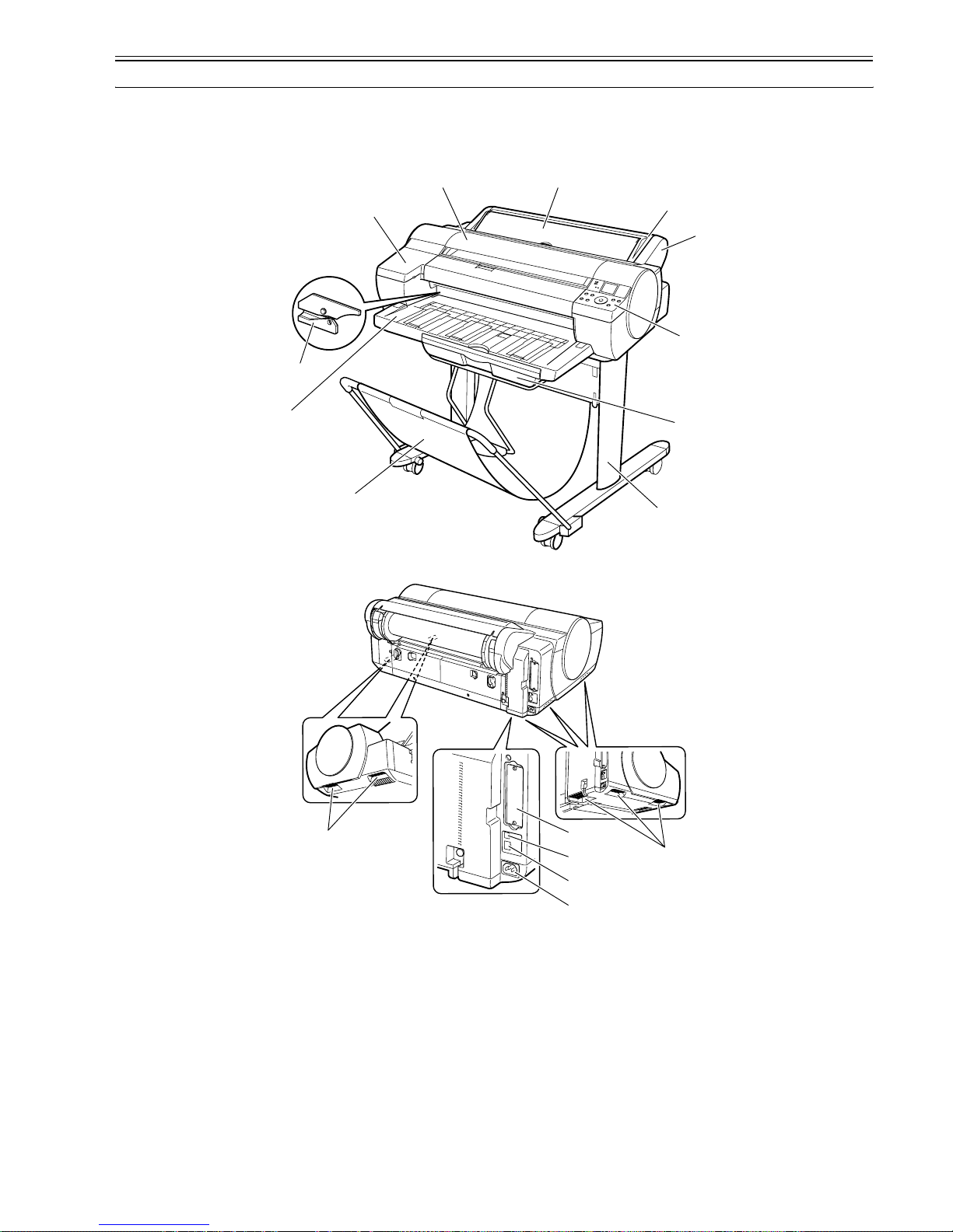
This printer is capable of printing on A4- to A1-size cut sheets and its maximum print width is 24 inches. This printer is a desktop large-format printer five-colors
(dye- and pigment-based colors) printer that can be used to print office documents as well as handy POP and posters. An roll feed unit is equipped for printing on
roll media.
F-1-1
F-1-2
T-1-1
[1] Top Cover [9] Roll Feed Unit
[2] Ink Tank Cover [10] Roll Feed Unit Cover
[3] Cutter [11] Manual Feed Cover
[4] Output Tray [12] Power Connector
[5] Basket [13] Ethernet Connector
[6] Stand [14] USB Port
[7] Cassette [15] Expansion Board Slot
[8] Operation Panel [16] Carrying Handle
[1] [11]
[10]
[2]
[8]
[9]
[4]
[5]
[7]
[6]
[3]
[15]
[16]
[16]
[14]
[13]
[12]
Chapter 1
1-2
1.2 Features
1.2.1 Features
0017-3851
- Black ink suitable for the selected media type is automatically selected from two types of black ink, "black ink" for vivid and glossy printing and "matte black
ink" for matte and high-quality printing.
- One-inch wide printhead having 2,560 nozzles per color, which are as many as the those of the existing models. High-density printhead technology "FINE" that
can satisfy both of beautiful and fast printing requirements of a high order is employed for accurate ejection of ultrasmall 4-pl drops of ink to the target positions.
Prints with 2400 x 1200 dpi resolution can be made at a high speed.
- Imaging processor "L-COA" incorporated for high-speed image data processing. High-speed processing of 5-color, 12-bit large-size images and printer control
for high-accuracy operation of high-density head can be performed with a single chip.
- Support for roll media, cassette paper pick-up, manual feed from front, and manual feed from top (4 -way paper su pply). A maxim um of 1.5 m m thick o f paper
can be manually fed from the front.
- Borderless printing on and auto cutting of roll media.
- Standard support for 10Base-T/100Base-TX. Standard support for USB 2.0 Hi-Speed. Optional support for IEEE1394.
- Data scanned using CanoScan can be easily printed on large-si ze paper just like a dedicated copier. Just pressing the Start button allows you to blow up an original
of up to A3 size in collaboration with Canon Image RUNNER.
- Support for remote notification utility which is used to send an E-mail when an alarm or error occurs.
Functional enhancements new to this model include:
- Enhanced ease of operation
A 160-by-128-dot-large LCD, coupled with the new [Paper Load/Eject] button, offers drastically enhanced ease of operation.
1.2.2 Printhead
0012-6187
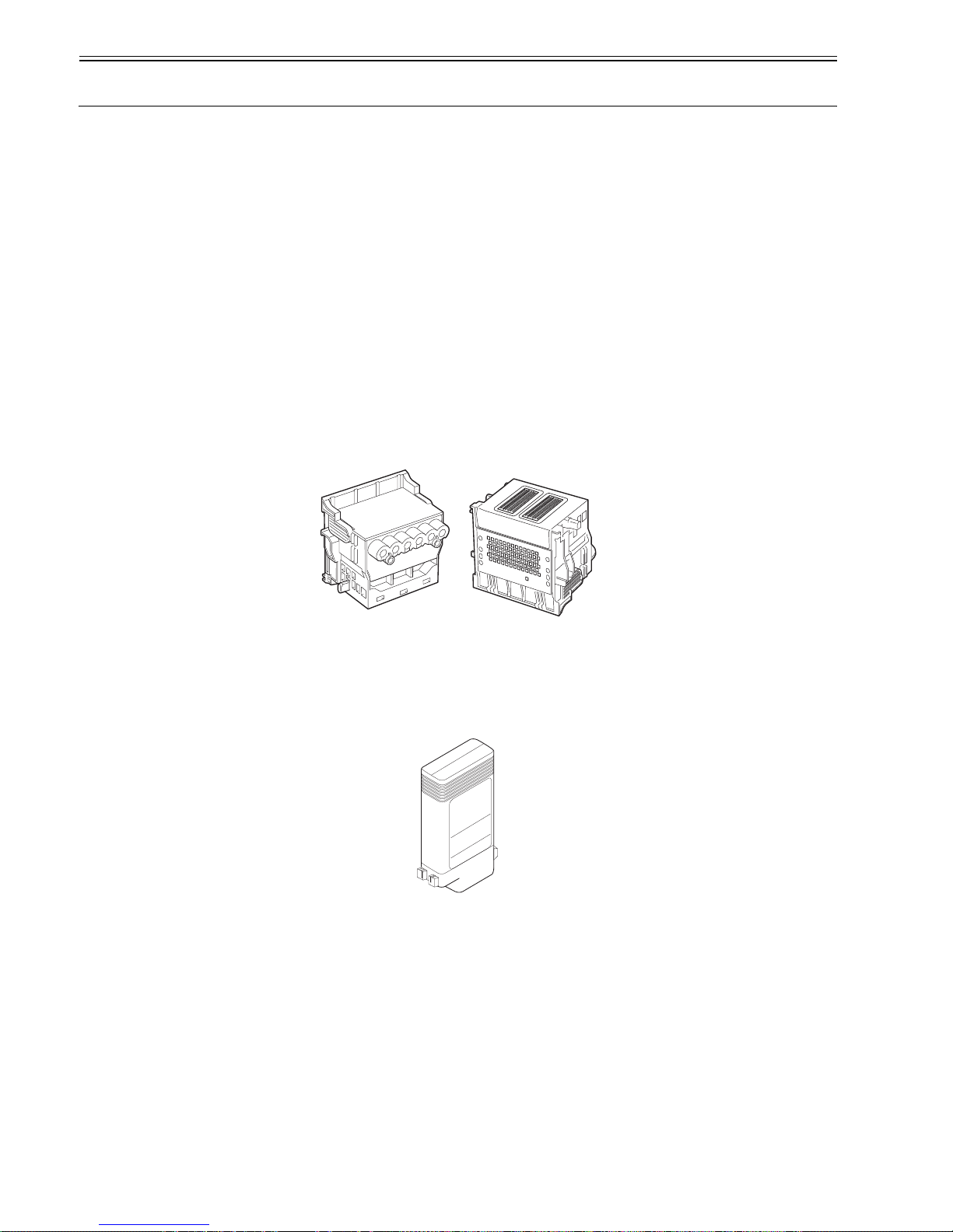
Printhead set on the carriage is a 6-color integral disposable type.
On the printhead, two rows of 1,280 nozzles (total 2,560 nozzles) are arranged in a staggered pattern. .
If print quality does not improve despite carrying out the specified cleaning, the printhead must be replaced with a new one. Generally, it is recommended that the
printhead be replaced about 12 months after you have opened the package.
F-1-3
1.2.3 Ink Tank
0012-6188
The ink tank is disposable.
There are four dye-based ink colors (black, cyan, magenta, and yellow) and one pigment-based ink color (matte black).
This printer features a mechanism by which only the correct color ink tank will fit in the given slot.
When the message No Ink is displayed, replace the ink tank with a new one. Also, each ink tank should generally be replaced six months after you have opened the
package.
F-1-4
Chapter 1
1-3
1.2.4 Cutter
0013-3524
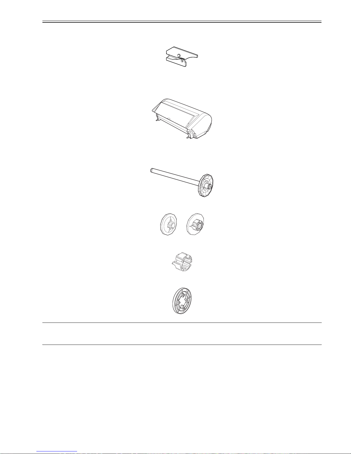
A round-blade cuter comes with the cutter unit.
F-1-5
1.2.5 Roll Feed Unit
0013-2512
Roll Feed Unit
The roll feed unit is optionally available to use roll media with this printer.
F-1-6
Roll holder set
This set consists of roll holder, holder stopper, 3-inch paper tube attachment, and borderless printing spacer (commonly used for 2-inch paper tube and 3-inch paper
tube).
[Roll holder]
F-1-7
[Holder stopper](for 2-inch paper tube and 3-inch paper tube)
F-1-8
[3-inch paper tube attachment]
F-1-9
[Borderless printing spacer]
F-1-10
MEMO:
A borderless printing spacer is used to perform borderless printing on A2-size (420 mm) roll media. This printer is furnished with a number of borderless printing
ink receiving channels on the platen to address multi-sized borderless printing needs. Borderless printing on A2-size roll media is made possible by using a spacer,
without needing to produce a new borderless printing ink receiving channel.
Chapter 1
1-4
1.2.6 Stand
0016-4087
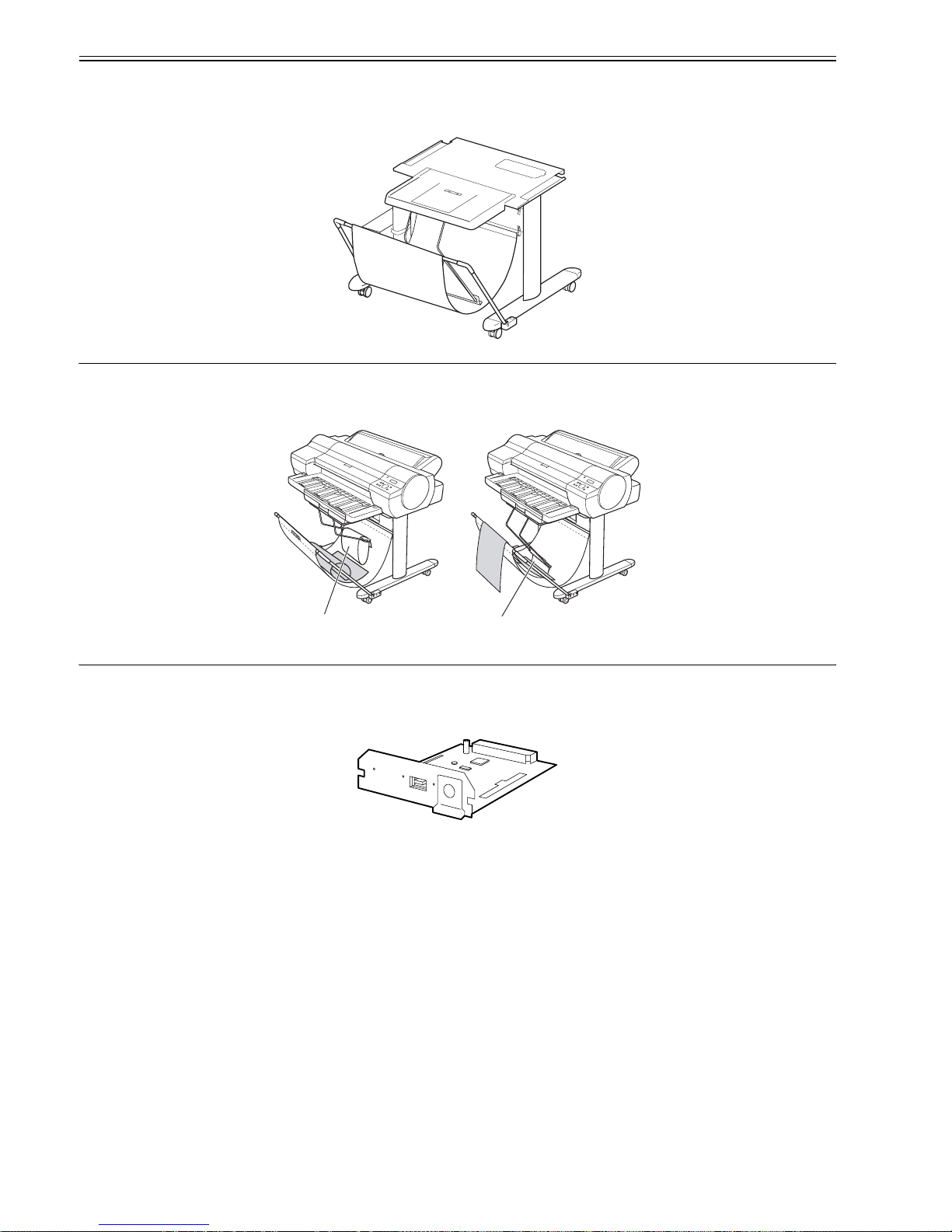
It is a stand that puts the printer. Equipped with casters so that the printer can be easily moved. The output stacker included with stand can use by the two ways of
the regular position or extended position.
F-1-11
MEMO:
- Use the output stacker in the regular position [A]. However, for the specified media, it can also be used in the extended position [B]. The media can be removed
more easily when the output stacker is in the extended position.
- The output stacker can accommodate one sheet. Remove each sheet before printing if you are printing a series of documents.
F-1-12
1.2.7 IEEE1394 (FireWire) Board
0016-8123
IEEE1394 (FireWire) expansion board (option)
An interface board that provides an additional IEEE1394 (FireWire) port.
F-1-13
[A]
[B]

Chapter 1
1-5
1.2.8 Consumables
0016-8109
Printhead
The consumable print head is the same as that supplied with the printer.
F-1-14
Ink Tanks
The consumable ink tanks are available in five colors (matte black, black, cyan, magenta, and yellow). They are the same as those supplied with the printer. Each
ink tank must be replaced with a new one six month after you have opened the package.
The ink tank that can be used with this printer is labeled "A".
F-1-15
Maintenance cartridge
The consumable maintenance cartridge is the same as that supplied with the printer.
F-1-16

Chapter 1
1-6
1.3 Product Specifications
1.3.1 Product Specifications
0017-4107
Type Bubble jet large-sized paper printer
Feeding system Automatic feeding of one roll media/Cassette paper feeding/One cut
sheet (manual feed from front)/One cut sheet (manual feed from top)
Feeding capacity - Roll media
One roll at the back/Outer diameter of roll: 150 mm or less/Inner
diameter of paper tube: 2 or 3 inches
- Cut sheet
Cassette:250 sheets(A4), 100 sheets(A3), 50 sheets(A2), manual feed:1
Delivery method Delivers the media with its printed side up in the forward direction.
Sheet delivery capability - Roll media
1 sheet
- Cut sheet
50 sheets (plain paper of A3 or smaller) or 20 sheets (plain paper of larger
than A3)
Cutter Automatically cuts paper laterally. Cartridge-type (with round blade)
Type of media - Roll media
Plain Paper, Plain Paper(High Quality), Plain Paper(High Grade),
Coated Paper, Heavyweight Coated Paper, Premium Matte Paper,
Glossy Photo Paper, Semi-Glossy Photo Paper, Economy Bond Paper,
Universal Bond Paper, Premium Coated Paper, Matte Coated Paper
90gsm, Glossy Photographic Paper 190gsm, Glossy Photographic Paper
240gsm, Satin Photographic Paper 240gsm, HW Glossy Photo
Paper(Heavyweight Glossy Photographic Paper 300gsm), HW Satin
Photo Paper(Heavyweight Satin Photographic Paper 300gsm), Premium
RC Photo Luster(Premium RC Photo Luster, 10 mil), Commercial
Proofing Paper(Commercial Proofing Paper 200gsm), Commercial RC
Proofing 210gsm, Commercial RC Proofing 270gsm
- Cut sheet (cassette)
Plain Paper, Plain Paper(High Quality), Plain Paper(High Grade), High
Resolution Paper, Coated Paper, Premium Matte Paper, Matte Photo
Paper, Glossy Paper, Photo Paper Pro, Photo Paper Plus, Photo Paper
Plus Semi-Gloss
-Cut sheet (manual feed from top)
Plain Paper, Plain Paper(High Quality), Plain Paper(High Grade), High
Resolution Paper, Coated Paper, Heavyweight Coated Paper, Premium
Matte Paper, Matte Photo Paper, Glossy Photo Paper, Semi-Glossy
Photo Paper, Glossy Paper, Photo Paper Pro, Photo Paper Plus, Photo
Paper Plus Semi-Gloss, Economy Bond Paper, Universal Bond Paper,
Premium Coated Paper, Matte Coated Paper 90gsm, Glossy
Photographic Paper 190gsm, Glossy Photographic Paper 240gsm, Satin
Photographic Paper 240gsm, HW Glossy Photo Paper(Heavyweight
Glossy Photographic Paper 300gsm), HW Satin Photo
Paper(Heavyweight Satin Photographic Paper 300gsm), Premium RC
Photo Luster(Premium RC Photo Luster, 10 mil), Commercial Proofing
Paper(Commercial Proofing Paper 200gsm), Commercial RC Proofing
210gsm, Commercial RC Proofing 270gsm
- Cut sheet (manual feed from front)
POP Board
Supported thickness Roll media: 0.08 to 0.8 mm
Cassette: 0.08 to 0.3 mm
Manual feed from top: 0.08 to 0.8 mm
Manual feed from front: 0.5 to 1.5 mm
Media size (Roll media) Width:203mm(8inch) X 610mm(24inch)
Length:203mm X 18m
Maximum outside diameter: 150 mm
Media size (Cut sheet) - Manual feed from top
Width:203mm(8inch) to 610mm(24inch)
Length:276mm to 1600mm
- Manual feed from front
Width:203mm(8inch) to 610mm(24inch)
Length:520mm X 914mm
- Cassette:only standard size
Width:203mm(8inch) X 432mm(17inch)
Length:279mm X 594mm

Chapter 1
1-7
Printable area (Roll media) Area excluding 3mm from the leading edge, 3 mm from the trailing edge,
and 3 mm from the left and right edges.
Borderless printing: 0 mm from the leading edge, trailing edge, and left
and right edges.
Width of media allowing borderless printing:
10"(254mm), B4(257mm), A3+(329mm), 14"(356mm), 16"(407mm),
A2(420mm), A2+/17"(432mm), B2(515mm), A1(594mm),
24"(610mm)
Media type allowing borderless printing:
Heavyweight Coated Paper, Premium Matte Paper, Glossy Photo Paper,
Semi-Glossy Photo Paper, Premium Coated Paper, Glossy Photographic
Paper 190gsm, Glossy Photographic Paper 240gsm, Satin Photographic
Paper 240gsm, HW Glossy Photo Paper, HW Satin Photo Paper,
Premium RC Photo Luster
Printable area (Cut sheet) Area excluding 3 mm from the leading edge, 3 mm from the trailing edge
(23 mm when supplied from manual feed from top or selected fine art),
and 3 mm from the left and right edges.
Printing recommendation area
(Roll media)
Area excluding 20 mm from leading edge, 5 mm from the traili ng edge
and 5 mm from the left and right edges (standard size).
Printing recommendation area
(Cut sheet)
Area excluding 20 mm from the leading edge, 27 mm from the trailing
edge, and 5 mm from the left and right edges (standard size).
Memory 256MB
Increase of memory: none
Firmware Flash ROM (update from USB and Ethernet, IEEE1394)
- Printer description language
GARO (Graphic Arts language with Raster Operation), HP-GL/2, HP
RTL
Interface USB2.0, Ethernet, IEEE1394 (option)
Operation panel LCD (160 X 128 dots), 12 keys, 5 LEDs
- Panel language
English
- Message language
English, German, French, Italian, Spanish, Chinese, Korean, Russianand
and Japanese
Printhead/Ink Tank type Printhead and separate ink tanks
Printhead [PF-03] Number nozzles: 2560 nozzles per color
Ink tank [PFI-102]MBK, BK, C, M, Y
Capacity: 130 ml per color (Ink tanks supplied with the printer contain
90 ml of each color.)
Detection functions (Cover
system)
Detects opening/closing of the top cover and ink tank cover.
Detection functions (Ink passage
system)
Detects presence/absence of ink tank, ink level (dot count and electrode),
presence/absence of the maintenance cartridge, waste ink full level,
presence/absence of the printhead, and opening/closing of the supply
valve.
Detection functions (Carriage
system)
Detects the ambient temperature, head temperature, prese nce/ absenc e of
the head, and no ink ejection.
Detection functions (Paper path
system)
Detects presence/absence of paper, cutter position, presence/absence of
the cassette, leading/trailing edge of paper, paper width, and skew.
Operating noise During printing: Approx. 52 dB (A) or less
During standby: Approx. 35 dB (A) or less
Operating environment Temperature: 15 to 30 degrees centigrade
Humidity: 10% to 80% without dew condensation
Print quality guaranteed
environment
Temperature: 15 to 30 degrees centigrade
Humidity: 10% to 80%RH
Power supply 100-120 VAC (50/60 Hz), 220-240 VAC (50/60 Hz)
Power consumption (Maximum) During printing: Max. 100 W
Power consumption In power save (sleep) mode: 5 W or less(220-240 VAC: 6W or less)
(When IEEE1394 board installed, 10W or less[220-240 VAC: 11W or
less])
During standby: 1 W or less
Printer unit dimensions
(WxDxH)
997 x 810 x 344 mm
Weight Approx. 55 kg

Chapter 1
1-8
1.4 Detailed Specifications
1.4.1 Print Speed and Direction
0017-4240

Chapter 1
1-9
T-1-2

Chapter 1
1-10
Media Type Print Priority
Print
Quality
Print-
Pass
Printing Direction
Print
Resolution
(dpi)
Used BK
ink
Plain Paper/
Recycled Paper
Plain Paper Office Document Standard 1/2 Bi-directional 1200x1200 MBK
Line Document/
Text
Draft 1 Bi-directional 1200x1200 MBK
1 Bi-directional 1200x1200 MBK
Standard 1 Bi-directional 1200x1200 MBK
High 2 Single-directional 1200x1200 MBK
2 Single-directional 1200x1200 MBK
Image Draft 1 Bi-directional 1200x1200 MBK
Standard 2 Bi-directional 1200x1200 MBK
High 4 Bi-directional 1200x1200 MBK
Plain Paper (High Quality) Office Document Standard 1/2 Bi-directional 1200x1200 MBK
Line Document/
Text
Draft 1 Bi-directional 1200x1200 MBK
1 Bi-directional 1200x1200 MBK
Standard 1 Bi-directional 1200x1200 MBK
High 2 Single-directional 1200x1200 MBK
2 Single-directional 1200x1200 MBK
Image Draft 1 Bi-directional 1200x1200 MBK
Standard 2 Bi-directional 1200x1200 MBK
High 4 Bi-directional 1200x1200 MBK
Plain Paper (High Grade) Office Document Standard 1/2 Bi-directional 1200x1200 MBK
Line Document/
Text
Draft 1 Bi-directional 1200x1200 MBK
1 Bi-directional 1200x1200 MBK
Standard 1 Bi-directional 1200x1200 MBK
High 2 Single-directional 1200x1200 MBK
2 Single-directional 1200x1200 MBK
Image Draft 1 Bi-directional 1200x1200 MBK
Standard 2 Bi-directional 1200x1200 MBK
High 4 Bi-directional 1200x1200 MBK
All Plain Paper_Conserve MBK Office Document Standard 1/2 Bi-directional 1200x1200 MBK
Line Document/
Text
Draft 1 Bi-directional 1200x1200 MBK
1 Bi-directional 1200x1200 MBK
Standard 1 Bi-directional 1200x1200 MBK
High 2 Single-directional 1200x1200 MBK
2 Single-directional 1200x1200 MBK
Image Draft 1 Bi-directional 1200x1200 MBK
Standard 2 Bi-directional 1200x1200 MBK
High 4 Bi-directional 1200x1200 MBK
Economy Bond Paper Office Document Standard 1/2 Bi-directional 1200x1200 MBK
Line Document/
Text
Draft 1 Bi-directional 1200x1200 MBK
1 Bi-directional 1200x1200 MBK
Standard 1 Bi-directional 1200x1200 MBK
High 2 Single-directional 1200x1200 MBK
2 Single-directional 1200x1200 MBK
Image Draft 1 Bi-directional 1200x1200 MBK
Standard 2 Bi-directional 1200x1200 MBK
High 4 Bi-directional 1200x1200 MBK
Universal Bond Paper Office Document Standard 1/2 Bi-directional 1200x1200 MBK
Line Document/
Text
Draft 1 Bi-directional 1200x1200 MBK
1 Bi-directional 1200x1200 MBK
Standard 1 Bi-directional 1200x1200 MBK
High 2 Single-directional 1200x1200 MBK
2 Single-directional 1200x1200 MBK
Image Draft 1 Bi-directional 1200x1200 MBK
Standard 2 Bi-directional 1200x1200 MBK
High 4 Bi-directional 1200x1200 MBK
Standard Paper 1569B 80g Office Document Standard 1/2 Bi-directional 1200x1200 MBK
Line Document/
Text
Draft 1 Bi-directional 1200x1200 MBK
1 Bi-directional 1200x1200 MBK
Standard 1 Bi-directional 1200x1200 MBK
High 2 Single-directional 1200x1200 MBK
2 Single-directional 1200x1200 MBK
Image Draft 1 Bi-directional 1200x1200 MBK
Standard 2 Bi-directional 1200x1200 MBK
High 4 Bi-directional 1200x1200 MBK
Standard Paper 1570B 90g Office Document Standard 1/2 Bi-directional 1200x1200 MBK
Line Document/
Text
Draft 1 Bi-directional 1200x1200 MBK
1 Bi-directional 1200x1200 MBK

Chapter 1
1-11
Coated Paper Coated Paper Line Document/
Text
Draft 1 Bi-directional 1200x1200 BK
1 Bi-directional 1200x1200 BK
Standard 2 Bi-directional 1200x1200 BK
High 4 Bi-directional 1200x1200 BK
4 Bi-directional 1200x1200 BK
Image Standard 4 Bi-directional 1200x1200 BK
High 8 Bi-directional 2400x1200 BK
Highest 12 Bi-directional 2400x1200 BK
Heavyweight Coated Paper Line Document/
Text
Draft 1 Bi-directional 1200x1200 BK
1 Bi-directional 1200x1200 BK
Standard 2 Bi-directional 1200x1200 BK
High 4 Bi-directional 1200x1200 BK
4 Bi-directional 1200x1200 BK
Image Standard 4 Bi-directional 1200x1200 BK
High 8 Bi-directional 2400x1200 BK
Highest 12 Bi-directional 2400x1200 BK
Extra Heavyweight Coated Paper Line Document/
Text
Draft 1 Bi-directional 1200x1200 BK
1 Bi-directional 1200x1200 BK
Standard 2 Bi-directional 1200x1200 BK
High 4 Bi-directional 1200x1200 BK
4 Bi-directional 1200x1200 BK
Image Standard 4 Bi-directional 1200x1200 BK
High 8 Bi-directional 2400x1200 BK
Highest 12 Bi-directional 2400x1200 BK
Recycled Coated Paper Line Document/
Text
Draft 1 Bi-directional 1200x1200 BK
1 Bi-directional 1200x1200 BK
Standard 2 Bi-directional 1200x1200 BK
High 4 Bi-directional 1200x1200 BK
4 Bi-directional 1200x1200 BK
Image Standard 4 Bi-directional 1200x1200 BK
High 8 Bi-directional 2400x1200 BK
Highest 12 Bi-directional 2400x1200 BK
High Resolution Paper Line Document/
Text
Draft 1 Bi-directional 1200x1200 BK
1 Bi-directional 1200x1200 BK
Standard 2 Bi-directional 1200x1200 BK
High 4 Bi-directional 1200x1200 BK
4 Bi-directional 1200x1200 BK
Image Standard 4 Bi-directional 1200x1200 BK
High 8 Bi-directional 2400x1200 BK
Highest 12 Bi-directional 2400x1200 BK
Premium Matte Paper Line Document/
Text
Draft 1 Bi-directional 1200x1200 BK
1 Bi-directional 1200x1200 BK
Standard 2 Bi-directional 1200x1200 BK
High 4 Bi-directional 1200x1200 BK
4 Bi-directional 1200x1200 BK
Image Standard 6 Bi-directional 1200x1200 BK
High 8 Bi-directional 2400x1200 BK
Highest 16 Bi-directional 2400x1200 BK
Matte Photo Paper Line Document/
Text
Draft 1 Bi-directional 1200x1200 BK
1 Bi-directional 1200x1200 BK
Standard 2 Bi-directional 1200x1200 BK
High 4 Bi-directional 1200x1200 BK
4 Bi-directional 1200x1200 BK
Image Standard 6 Bi-directional 1200x1200 BK
High 8 Bi-directional 2400x1200 BK
Highest 16 Bi-directional 2400x1200 BK
Colored Coated Paper Image Standard 4 Bi-directional 1200x1200 MBK
High 8 Bi-directional 1200x1200 MBK
Premium Coated Paper Line Document/
Text
Draft 1 Bi-directional 1200x1200 BK
1 Bi-directional 1200x1200 BK
Standard 2 Bi-directional 1200x1200 BK
High 4 Bi-directional 1200x1200 BK
4 Bi-directional 1200x1200 BK
Image Standard 4 Bi-directional 1200x1200 BK
High 8 Bi-directional 2400x1200 BK
Highest 12 Bi-directional 2400x1200 BK
Media Type Print Priority
Print
Quality
Print-
Pass
Printing Direction
Print
Resolution
(dpi)
Used BK
ink

Chapter 1
1-12
Photo Paper Glossy Photo Paper Image Standard 6 Bi-directional 1200x1200 BK
High 8 Bi-directional 2400x1200 BK
Highest 16 Bi-directional 2400x1200 BK
Semi-Glossy Photo Paper Image Standard 6 Bi-directional 1200x1200 BK
High 8 Bi-directional 2400x1200 BK
Highest 16 Bi-directional 2400x1200 BK
Photo Paper Plus Image Standard 6 Bi-directional 1200x1200 BK
High 8 Bi-directional 2400x1200 BK
Highest 16 Bi-directional 2400x1200 BK
Photo Paper Plus Semi-Gloss Image Standard 6 Bi-directional 1200x1200 BK
High 8 Bi-directional 2400x1200 BK
Highest 16 Bi-directional 2400x1200 BK
Photo Paper Pro Image Standard 6 Bi-directional 1200x1200 BK
High 8 Bi-directional 2400x1200 BK
Highest 16 Bi-directional 2400x1200 BK
Glossy Paper Image Standard 6 Bi-directional 1200x1200 BK
High 8 Bi-directional 2400x1200 BK
Highest 16 Bi-directional 2400x1200 BK
Heavyweight Glossy Photo Paper 2 Image Standard 6 Bi-directional 1200x1200 BK
High 8 Bi-directional 2400x1200 BK
Highest 16 Bi-directional 2400x1200 BK
Heavywght SemiGlos Photo Paper 2 Image Standard 6 Bi-directional 1200x1200 BK
High 8 Bi-directional 2400x1200 BK
Highest 16 Bi-directional 2400x1200 BK
Satin Photographic Paper 190gsm Image Standard 6 Bi-directional 1200x1200 BK
High 8 Bi-directional 2400x1200 BK
Highest 16 Bi-directional 2400x1200 BK
Premium RC Photo Luster , 10 mil Image Standard 6 Bi-directional 1200x1200 BK
High 8 Bi-directional 2400x1200 BK
Highest 16 Bi-directional 2400x1200 BK
Instant Dry Papers Glossy 200g Image Standard 6 Bi-directional 1200x1200 B K
High 8 Bi-directional 2400x1200 BK
Highest 16 Bi-directional 2400x1200 BK
Instant Dry Papers Satin 200g Image Standard 6 Bi-directional 1200x1200 BK
High 8 Bi-directional 2400x1200 BK
Highest 16 Bi-directional 2400x1200 BK
Photo Paper High Glossy 250g Image Standard 6 Bi-directional 1200x1200 BK
High 8 Bi-directional 2400x1200 BK
Highest 16 Bi-directional 2400x1200 BK
Photo Paper Semi Matt 250g Image Standard 6 Bi-directional 1200x1200 BK
High 8 Bi-directional 2400x1200 BK
Highest 16 Bi-directional 2400x1200 BK
Photo Paper Satin 240g Image Standard 6 Bi-directional 1200x1200 BK
High 8 Bi-directional 2400x1200 BK
Highest 16 Bi-directional 2400x1200 BK
Photo Paper Pearl 260g Image Standard 6 Bi-directional 1200x1200 BK
High 8 Bi-directional 2400x1200 BK
Highest 16 Bi-directional 2400x1200 BK
Proofing Paper Proofing Paper Image Standard 6 Bi-directional 1200x1200 BK
High 8 Bi-directional 2400x1200 BK
Highest 16 Bi-directional 2400x1200 BK
Professional Proof and Photo Glossy 195g Image Standard 6 Bi-directional 1200x1200 BK
High 8 Bi-directional 2400x1200 BK
Highest 16 Bi-directional 2400x1200 BK
Professional Proof and Photo Semiglossy
195g
Image Standard 6 Bi-directional 1200x1200 BK
High 8 Bi-directional 2400x1200 BK
Highest 16 Bi-directional 2400x1200 BK
Professional Proof and Photo Semigloss
255g
Image Standard 6 Bi-directional 1200x1200 BK
High 8 Bi-directional 2400x1200 BK
Highest 16 Bi-directional 2400x1200 BK
Media Type Print Priority
Print
Quality
Print-
Pass
Printing Direction
Print
Resolution
(dpi)
Used BK
ink

Chapter 1
1-13
Synthetic Paper Synthetic Paper Image Standard 6 Bi-directional 1200x1200 BK
High 8 Bi-directional 2400x1200 BK
Highest 16 Bi-directional 2400x1200 BK
Adhesive Synthetic Paper Image Standard 6 Bi-directional 1200x1200 BK
High 8 Bi-directional 2400x1200 BK
Highest 16 Bi-directional 2400x1200 BK
Board POP Board Image Standard 4 Bi-directional 1200x1200 MBK
High 8 Bi-directional 1200x1200 MBK
Adhesive Matt
Paper
High Resolution Graphic Paper Self ADH Image Standard 6 Bi-directional 1200x1200 BK
High 8 Bi-directional 2400x1200 BK
Highest 16 Bi-directional 2400x1200 BK
CAD CAD Tracing Paper Line Document/
Text
Draft 1 Bi-directional 1200x1200 MBK
1 Bi-directional 1200x1200 MBK
Standard 2 Bi-directional 1200x1200 MBK
High 4 Bi-directional 1200x1200 MBK
4 Bi-directional 1200x1200 MBK
CAD Translucent Matte Film Line Document/
Text
Draft 1 Bi-directional 1200x1200 MBK
1 Bi-directional 1200x1200 MBK
Standard 2 Bi-directional 1200x1200 MBK
High 4 Bi-directional 1200x1200 MBK
4 Bi-directional 1200x1200 MBK
Special Special 1 Image Standard 6 Bi-directional 1200x1200 BK
High 8 Bi-directional 2400x1200 BK
Highest 16 Bi-directional 2400x1200 BK
Special 2 Image Standard 6 Bi-directional 1200x1200 BK
High 8 Bi-directional 2400x1200 BK
Highest 16 Bi-directional 2400x1200 BK
Special 3 Image Standard 6 Bi-directional 1200x1200 BK
High 8 Bi-directional 2400x1200 BK
Highest 16 Bi-directional 2400x1200 BK
Special 4 Image Standard 6 Bi-directional 1200x1200 BK
High 8 Bi-directional 2400x1200 BK
Highest 16 Bi-directional 2400x1200 BK
Special 5 Image Standard 6 Bi-directional 1200x1200 BK
High 8 Bi-directional 2400x1200 BK
Highest 16 Bi-directional 2400x1200 BK
Media Type Print Priority
Print
Quality
Print-
Pass
Printing Direction
Print
Resolution
(dpi)
Used BK
ink

Chapter 1
1-14
1.4.2 Interface Specifications
0012-6200
a. USB (standard)
(1) Interface type
USB 2.0 Hi-Speed (Full speed (12 Mbits/sec), High speed (480 Mbits/sec))
(2) Data transfer system
Control transfer
Bulk transfer
(3) Signal level
Compliant with the USB standard.
(4) Interface cable
Twisted-pair shielded cable, 5.0 m max.
Compliant with the USB standard.
Wire materials: AWG No.28, data wire pair (AWF: American Wire Gauge)
AWG No.20 to No.28, power distribution wire pair
(5) Interface connector
Printer side: Series B receptacle compliant with USB standard
Cable side: Series B plug compliant with USB standard
b. Network (standard)
(1) Interface type
Interface compliant with IEEE802.3
(2) Data transfer system
10Base-T/100Base-TX
(3) Signal level
Input: Threshold
10Base-T: Max. +585 mV, Min. +300 mV
100Base-TX: Turn-on +1000 mV diff pk-pk, Turn-off +200 mV diff pk-pk
Output:
10Base-T: +2.2 V to +2.8 V
100Base-TX: +0.95 to +1.05 V
(4) Interface cable
Category 5 (UTP or FTP) cable, 100 m or shorter
Compliant with ANSI/EIA/TIA-568A or ANSI/EIA/TIA-568B
(5) Interface connector
Printer side: Compliant with IEEE802.3, ANSI X3.263, ISO/IEC60603-7
c. IEEE1394 (option)
(1) Interface type
Interface compliant with IEEE1394-1995, P1394a (Version 2.0)
(2) Data transfer system
Asynchronous transfer
(3) Signal level
Input:
Differential input voltage:
During S100 settlement: +173 mV to +260 mV
During data reception: +142 mV to +260 mV
During S200 settlement: +171 mV to +262 mV
During data reception: +132 mV to +260 mV
During S400 settlement: +168 mV to +265 mV
During data reception: +118 mV to +260 mV
Output:
Differential output voltage: +172 mV to +265 mV
(4) Interface cable
Twisted-pair shielded cable, 4.5 m max.
Compliant with IEEE1394-1995 standard or P1394a (Version 2.0) standard
(5) Interface connector
Printer side: 6-pin connector (socket) compliant with IEEE1394 standard
Cable side: 6-pin connector (plug) compliant with IEEE1394 standard
Cable side: RJ-45 type compliant with ANSI/EIA/TIA-568A or ANSI/EIA/TIA-568B
Chapter 1
1-15
1.5 Names and Functions of Components
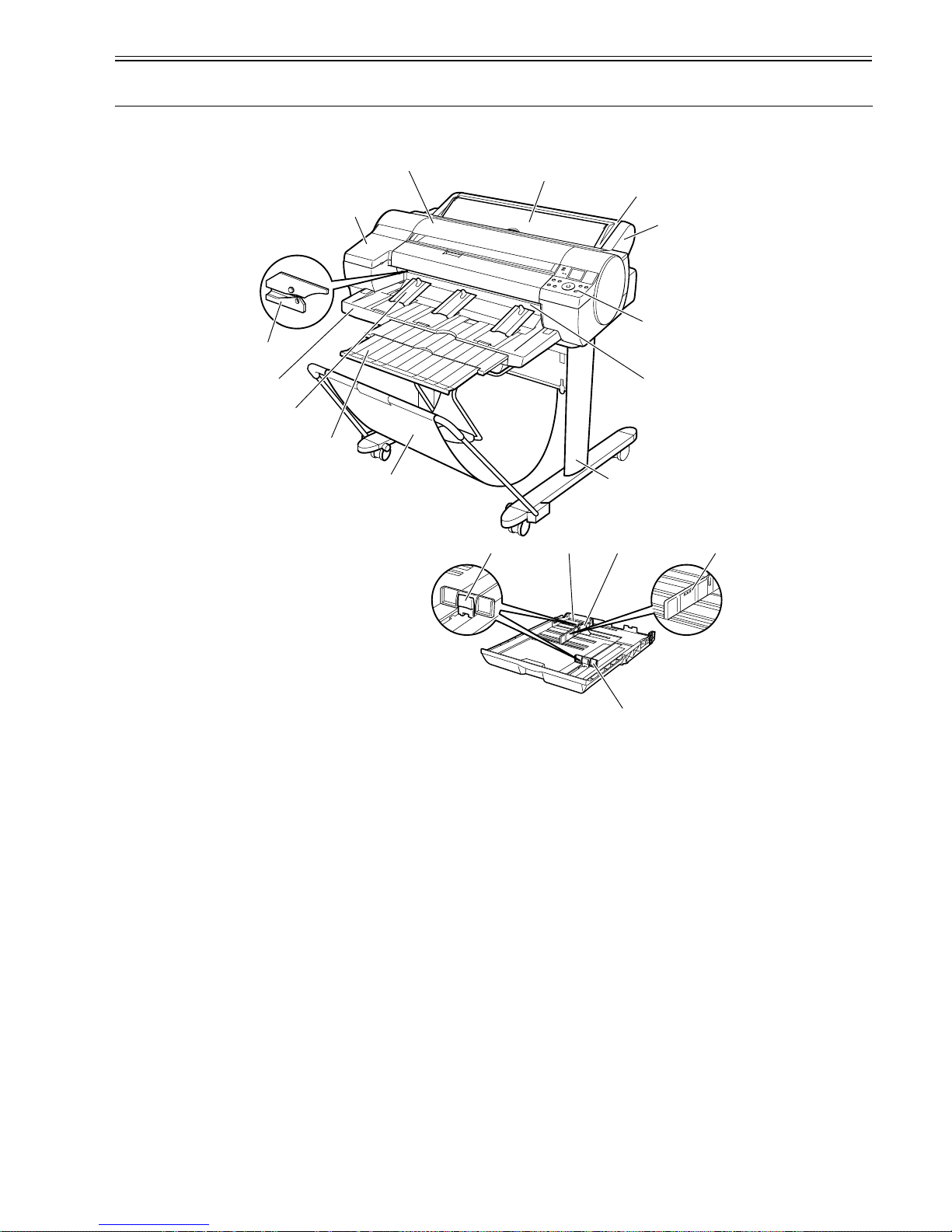
1.5.1 Front
0017-4553
F-1-17
[1] Top cover
Open this cover when installing the printhead or remove the media jammed inside the printer.
[2] Ink tank cover
Open this cover when replacing ink tanks.
[3] Cutter
A round-blade cutter cuts roll media automatically. It is stowed inside when it is out of use.
[4] Output tray
Printed documents are ejected into the output tray.
[5] Output guides
These guides support printed documents as they are ejected, preventing jams. Raise the guides before printing on rolls.
[6] Output tray extension
An extension to prevent ejected paper from falling to the floor. Pull out the extension to match the paper size before printing on sheets.
[7] Basket
Receives printed matter as it is ejected. Only one sheet can be housed in the basket.
[8] Stand
The base on which the printer is mounted. The stand equipped with casters is easy to move.
[9] Paper eject slot (paper tray front loading port)
All printed matter is ejected from this port. In loading thick paper, insert it into this port.
[10] Operation panel
Contains the power button, online button display and so on.
[11] Roll feed unit
Load roll media on this unit.
[12] Roll feed unit cover
Load roll media with this cover open.
[13] Paper tray cover
Load cut sheet at the paper tray top loading port with this cover open. This cover is opened, and the cut sheet is set at top manual feed slot.
[14] Cassette
Load sheets in this tray.
[15] Guide lever
Squeeze these levers to slide the guides.
[16] Length guide
Adjust this guide to hold paper lengthwise.
[17] Maximum capacity line
A guide line indicating how many sheets can be loaded. Do not load paper over this line.
[18] Width guide
[1]
[13]
[12]
[2]
[10]
[11]
[7]
[4]
[5]
[6]
[9]
[8]
[17][18][14]
[16]
[15]
[3]

Chapter 1
1-16
Adjust this guide to hold paper widthwise.
 Loading...