

Canon iP4200 - PIXMA Photo Printer Service Manual

PIXMA iP4200
SERVICE MANUAL
Revision 0
QY8-13A9-000
COPYRIGHT©2005 CANON INC. CANON PIXMA iP4200 072005 XX 0.00-0
Scope
This manual has been issued by Canon Inc., to provide the service technicians of this product with the information
necessary for qualified persons to learn technical theory, installation, maintenance, and repair of products. The manual
covers information applicable in all regions where the product is sold. For this reason, it may contain information that is
not applicable to your region.
Revision

This manual could include technical inaccuracies or typographical errors due to improvements or changes made to the
product. When changes are made to the contents of the manual, Canon will release technical information when
necessary. When substantial changes are made to the contents of the manual, Canon will issue a revised edition.
The following do not apply if they do not conform to the laws and regulations of the region where the manual or product
is used:
Trademarks
Product and brand names appearing in this manual are registered trademarks or trademarks of the respective holders.
Copyright
All rights reserved. No parts of this manual may be reproduced in any form or by any means or translated into another
language without the written permission of Canon Inc., except in the case of internal business use.
Copyright © 2005 by Canon Inc.
CANON INC.
Inkjet Device Quality Assurance Div. 2
451, Tsukagoshi 3-chome, Saiwai-ku, Kawasaki-shi, Kanagawa 212-8530, Japan

I. MANUAL OUTLINE
This manual consists of the following three parts to provide information necessary to service the PIXMA iP4200:
Part 1: Maintenance
Information on maintenance and troubleshooting of the PIXMA iP4200
Part 2: Technical Reference
N
ew technology and technical information such as FAQ's (Frequently Asked Questions) of the PIXMA iP4200
Part 3: Appendix
Block diagrams and pin layouts of the PIXMA iP4200
Reference:
This manual does not provide sufficient information for disassembly and reassembly procedures. Refer to the graphics in
the separate Parts Catalog.

II. TABLE OF CONTENTS
Part 1: MAINTENANCE
1. MAINTENANCE
1
-1. Adjustment, Periodic Maintenance, Periodic Replacement Parts, and Replacement Consumables by
Service Engineer
1
-2. Customer Maintenance
1
-3. Product Life
1
-4. Special Tools
1
-5. Serial Number Location
2. LIST OF ERROR DISPLAY / INDICATION
2
-1. Operator Call Errors
2
-2. Service Call Errors
2
-3. Warnings
2
-4. Troubleshooting by Symptom
3. REPAIR
3
-1. Notes on Service Part Replacement (and Disassembling / Reassembling)
3
-2. Special Notes on Repair Servicing
3
-3. Adjustment / Settings
(1) Paper feed motor adjustment
(2) Grease application
(3) Waste ink counter setting
(4) User mode
(5) Service mode
Service test print,
EEPROM initialization, Waste ink counter reset
Destination settings
3
-4. Verification Items
(1) Service test print
(2) EEPROM information print
4. PRINTER TRANSPORTATION
Part 2: TECHNICAL REFERENCE
1. NEW TECHNOLOGIES
2. CLEANING MODE AND AMOUNT OF INK PURGED
3. PRINT MODE
4
. FAQ (Problems Specific to the iP4000 and Corrective Actions)
Part 3: APPENDIX
1. BLOCK DIAGRAM
2. CONNECTOR LOCATION AND PIN LAYOUT
2
-1. Logic Board Ass'y
2
-2. Carriage Board (Print Head Connector)
PIXMA iP4200 Specifications

P
art 1
MAINTENANCE
1. MAINTENANCE
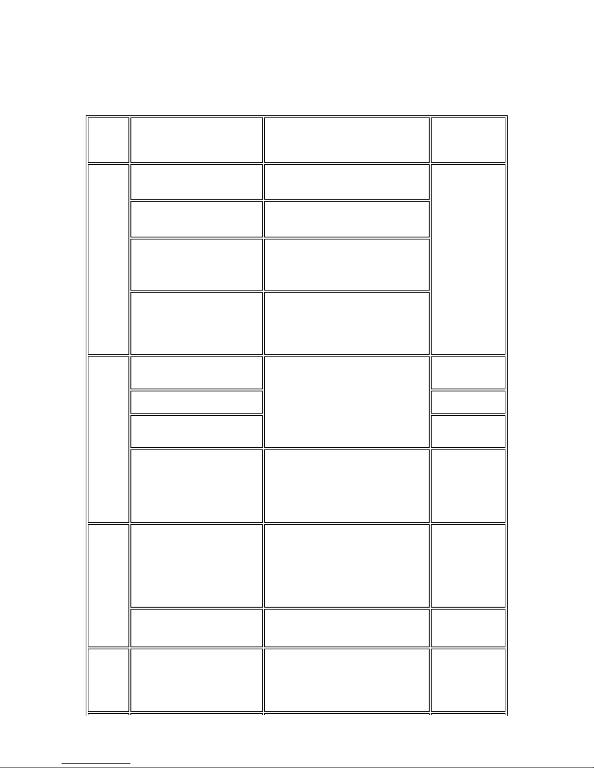
1-1. Adjustment, Periodic Maintenance, Periodic Replacement Parts, and
Replacement Consumables by Service Engineer
(1) Adjustment
Adjustment Timing Purpose Tool
Approx.
time
Destination
settings
(EEPROM
settings)
At logic board replacement To set the destination.
None.
Perform in the
service mode.
1 min.
Waste ink
counter
resetting
(EEPROM
settings)
- At logic board replacement
- At waste ink absorber
replacement
To reset the waste ink counter.
None.
Perform in the
service mode.
1 min.
Paper feed
motor position
adjustment
At paper feed motor
replacement
To adjust the belt tension.
(Position the paper feed motor so
that the belt is stretched tight.)
None.
5 min.
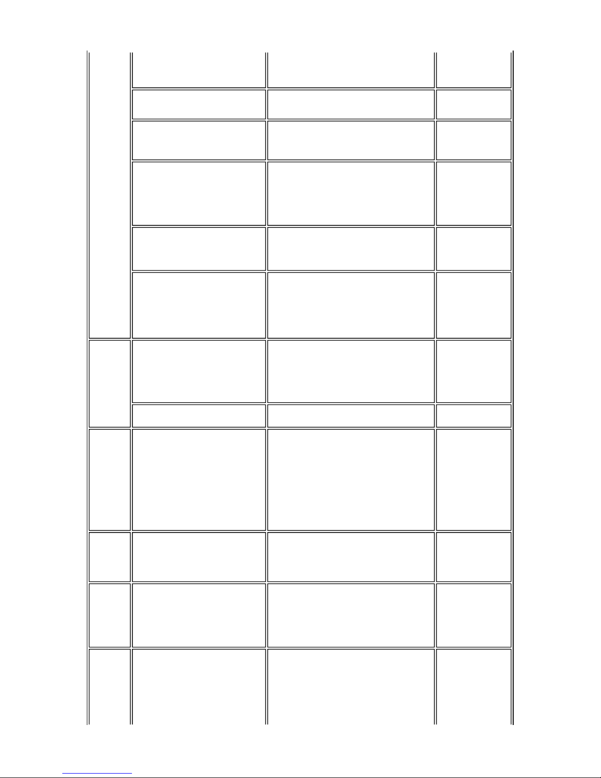
CD / DVD
detection sensor
light volume
correction
*1
- At logic board replacement
- At carriage unit replacement
To correct the light volume for
the CD / DVD detection sensor.
None.
Perform in the
service mode.
2 min.
Grease
application
- At carriage unit replacement
- At PR shaft ass'y replacement
- At CL base / gear replacement
- To maintain sliding properties
of the carriage shaft and the lift
cam shaft.
- To protect the printer's sliding
portions (gears).
FLOIL KG-107A 1 min.
Ink system
function check
- At logic board replacement
- At platen unit replacement
- At carriage unit replacement
To maintain detection
functionality for presence of the
ink tanks and each ink tank
position.
None.
Perform in the
service mode.
1 min.
1-1
Note: DO NOT loosen the red screws at both ends of the carriage shaft, securing the print head position, as they are
not re-adjustable.
The red screws securing the paper feed motor may be loosened only at replacement of the paper feed motor
unit.
*1: Only for CD / DVD printing supported regions.
(2) Periodic maintenance
No periodic maintenance is necessary.
(3) Periodic replacement parts
There are no parts in this printer that require periodic replacement by a service engineer.
(4) Replacement consumables
There are no consumables that require replacement by a service engineer.
1-2. Customer Maintenance
Adjustment Timing Purpose Tool
Approx.
time
Print head
alignment
At print head replacement.
To ensure accurate dot
placement.
- Printer buttons
- Computer
(automatic settings
via the printer
driver)
3 min.
Print head
cleaning
When print quality is not
satisfying.
To improve nozzle conditions. - Printer buttons
- Computer (settings
via the printer
driver)
1 min.
Print head deep
cleaning
When print quality is not
satisfying, and not improved by
print head cleaning.
To improve nozzle conditions. Computer (settings
via the printer driver)
2 min.
Ink tank
replacement
When an ink tank becomes
empty. ("No ink error" via the
computer, or ink tank LED
flashing fast in red)
----- -----
2 min.
Paper feed roller
cleaning
When necessary To clean the paper feed
rollers.
Printer buttons 2 min.
CD / DVD print
position
adjustment
At CD / DVD printing, when
necessary
To correct CD / DVD print
position.
Computer (application
software)
5 min.
Bottom plate
cleaning
When the back side of the paper
is smeared
To clean the platen ribs.
- Plain paper
- Computer (settings
via the printer
driver)
1 min.
ASF sub- roller
cleaning
When the paper fed from the
ASF is smeared due to ink mist
attached to the ASF sub-rollers.
To clean the ASF sub-rollers.
- Plain paper
- Printer buttons
[See Part 2, 4. FAQ,
How to make and
set the ASF subroller cleaning
sheet, for details]
1 min.
1-2
1-3. Product Life
(1) Printer
Specified print volume (I) or the years of use (II), whichever comes first.
(I) Print volume
PIXMA iP4200: 18,000 pages
(II) Years of use
PIXMA iP4200: 5 years of use
(2) Print head
Print volume: 18,000 pages
(3) Ink tank (target value)
Black 1,500 character pattern 8,300 pages
Color
A4, 7.5% duty per color pattern 5,400 pages
A4, photo, borderless printing 400 pages
4 x 6, photo, borderless printing 3,200 pages
Postcard, photo, borderless printing 700 pages
Black 1,500 character pattern 8,300 pages
Color
A4, 7.5% duty per color pattern 5,400 pages
A4, photo, borderless printing 400 pages
4 x 6, photo, borderless printing 3,200 pages
Postcard, photo, borderless printing 700 pages
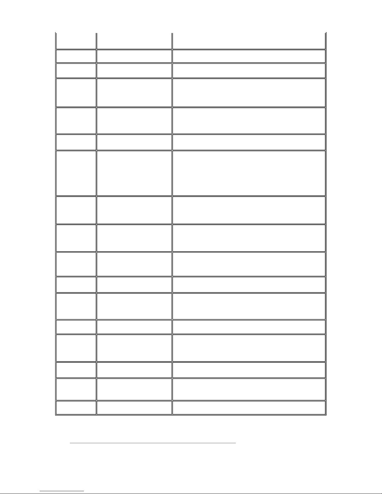
Pattern Ink tank used Print yield
Black text
PGI-5BK Approx. 820 pages
CLI-8BK
Color chart
CLI-8BK Approx. 2,000 pages
PGI-5BK Approx. 1,450 pages
CLI-8Y Approx. 540 pages
CLI-8M Approx. 600 pages
CLI-8C Approx. 850 pages
Photo chart
CLI-8BK Approx. 1,650 pages
CLI-8Y Approx. 310 pages
CLI-8M Approx. 290 pages
1-3
CLI-8C Approx. 430 pages
Black text: When printing the Canon standard pattern (1,500 characters per page) on A4 size plain paper, with
the default settings in the Windows XP driver, using Word 2003.
Color chart: When printing the ISO/JIS-SCID N5 pattern on A4 size plain paper in bordered printing, with the
default settings in the Windows XP driver, using Photoshop 7.0.
Photo chart: When printing the Canon standard pattern on 4" x 6" Photo Paper Plus Glossy in borderless
printing, with the default settings in the Windows XP driver, using Windows XP Photo Printing
Wizard.
The print yield in the table above is an average value measured in continuous printing, using the ink tank
immediately after it is unsealed, until the ink is out. Ink yield may vary depending on texts and photos printed,
application software, print mode, and type of paper used.
1-4. Special Tools
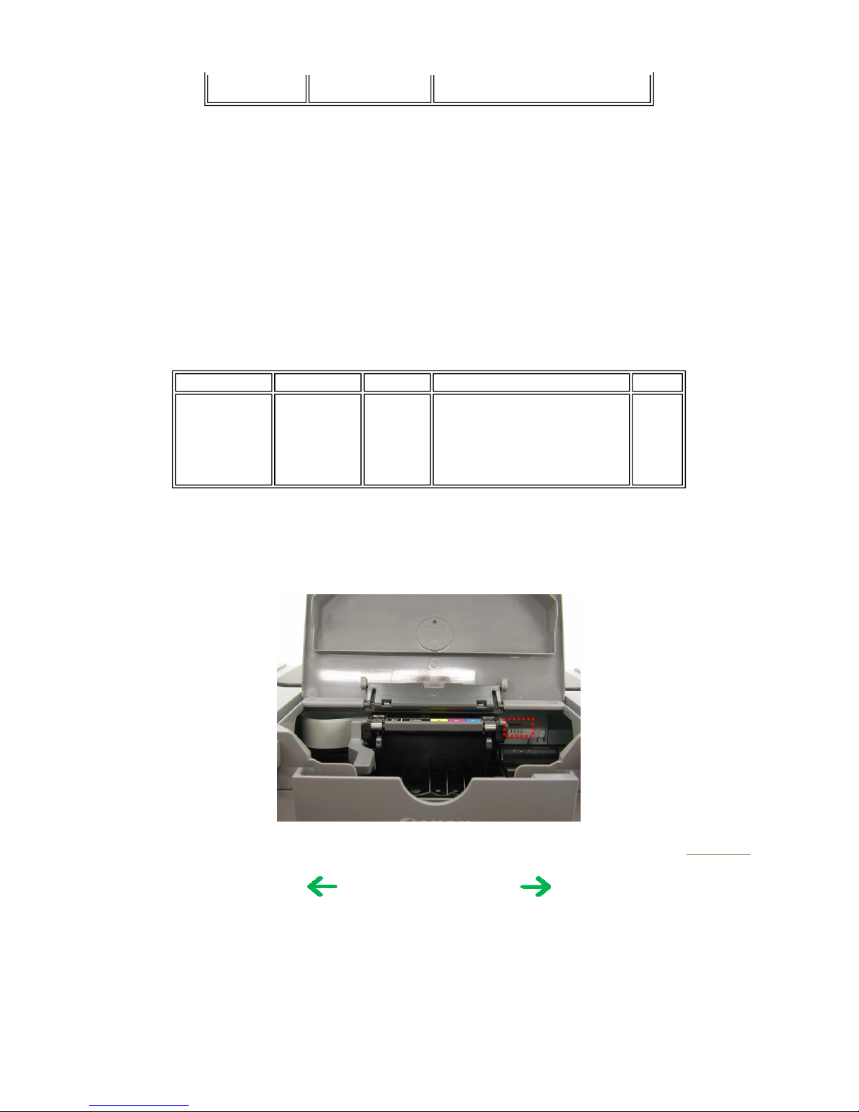
1-5. Serial Number Location
On the carriage flexible cable holder (visible on the right of the carriage after the printer is turned on, the access cover
is opened, and the carriage moves to the center).
To the top
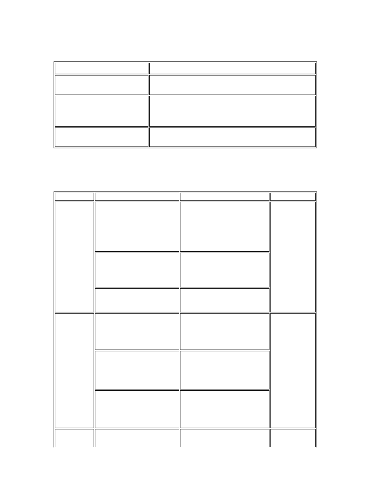
Name Tool No. Price Application Remarks
Grease FLOIL
KG-107A
QY9-0057-000 US$2.00 To be applied to the sliding portions
of the carriage shaft and lift cam
shaft.
In
common
with the
S500
and
S520.
<Part 1: 1. MAINTENANCE>
1-4
2. LIST OF ERROR DISPLAY / INDICATION
Errors are indicated by the LED, and warnings are displayed on the monitor of the computer connected to the printer.
2-1. Operator Call Errors (by Alarm LED Blinking in Orange)
Alarm
LED
blinking
in orange
Error [Error code]
Solution Remarks
2 times
No paper. (ASF) [1000] Set the paper in the ASF, and press the
Resume/Cancel button.
No CD / DVD tray. [1001]
*1
Set the CD / DVD tray, and press the
Resume/Cancel button.
No paper in the cassette. [1003]
(No paper in the front paper feed
cassette.)
Set the paper in the cassette, and press the
Resume/Cancel button.
No CD / DVD. [1002]
*1
Set a CD or DVD in the CD / DVD tray
(which is ejected at error occurrence), and
insert the CD / DVD tray in the proper
position. Then, press the Resume/Cancel
button.
3 times
Paper jam. [1300] Remove the jammed paper, and press the
Resume/Cancel button.
Error in paper
feeding from the
ASF.
Paper jam in the rear guide. [1303] Error in the duplex
printing unit.
Paper jam in the under guide.
[1304]
Error in paper
feeding from the
cassette.
Front door close error. [1250] Open the paper output tray. The error is
indicated if the
paper output tray
is closed at start of
a print job, or
while a print job is
being performed.
4 times No ink. [1600] Replace the empty ink tank(s), or press the
Resume/Cancel button.
Pressing the
Resume/Cancel
button will exit the
error without ink
tank replacement,
however, ink may
run out during
printing.
Ink tank not installed. [1660] Install the applicable ink tank(s) properly,
and confirm that the LED's of all the ink
tanks light red.
5 times The print head is not installed
[1401], or it is not properly
installed (Print head temperature
sensor error [1403] / Faulty
EEPROM data of the print head
[1405]).
Install the print head properly.
1-5
6 times
Inner cover open. [1841]
*2
Close the inner cover, and press the
Resume/Cancel button.
Inner cover open during printing
on paper. [1846]
*2
Close the inner cover, and press the
Resume/Cancel button.
Inner cover open during printing
on paper (print continuable).
[1851]
*1
Close the inner cover, and press the
Resume/Cancel button.
Inner cover open during printing
on paper (print NOT continuable).
[1856]
*1
Close the inner cover, and press the
Resume/Cancel button to clear the error.
The paper being printed at error occurrence
will be ejected without printing the
remaining data for the ejected paper, then
printing will resume from the next page.
Inner cover closed during CD /
DVD printing (print continuable).
[1850]
*1
Open the inner cover which functions as the
CD / DVD tray feeder, set the CD / DVD
tray in the feeder, and press the
Resume/Cancel button.
Inner cover closed during CD /
DVD printing (print NOT
continuable). [1855]
*1
Open the inner cover, and press the
Resume/Cancel button to clear the error.
The CD or DVD being printed at error
occurrence will be ejected without printing
the remaining data for the ejected CD or
DVD, then the next print job will be done.
7 times
Multiple ink tanks of the same
color installed. [1681]
Replace the wrong ink tank(s) with the
correct one(s).
Ink tank in a wrong position.
[1680]
Install the ink tank(s) in the correct
position.
8 times Warning: The waste ink absorber
becomes almost full. [1700]
Pressing the Resume/Cancel button will
exit the error, and enable printing.
The service call
error, indicating
the waste ink
absorber is full, is
likely to occur
soon.
9 times The connected digital camera or
digital video camera does not
support Camera Direct Printing.
[2001]
Remove the cable between the camera and
the printer.
10 times Automatic duplex printing cannot
be performed. [1310]
Press the Resume/Cancel button to eject the
paper being used at error occurrence.
Printing will resume from on the front side
of the next page.
Data which was to
be printed on the
back side of paper
at error occurrence
is skipped (not
printed).
11 times
Failed in automatic print head
alignment. [2500]
Press the Resume/Cancel button.
- If paper is being fed at error occurrence,
the error is indicated after the paper is
ejected.
- If the error occurs, the print head
alignment values are not changed.
- After exit from the error by the
The error is
indicated when the
pattern is not
printed due to no
ink or non-ejection
of ink, or when the
sensor's AD value
1-6

*1: Only for models supporting CD / DVD printing
*2: Only for models not supporting CD / DVD printing
2-2. Service Call Errors (by Cyclic Blinking in Orange (Alarm LED) and Green
(Power LED), or Alarm LED Lit in Orange)
Resume/Cancel button, the automatic print
head alignment will not be re-done.
is incorrect.
13 times
The remaining ink amount
unknown. [1683]
An ink tank which has once been empty is
installed. Replace the applicable ink tank
with a new one.
Printing with a
once-empty or
refilled ink tank
can damage the
print head.
If printing is
continued without
replacing the "nogood" ink tank,
press the
Resume/Cancel
button for 5 sec. or
longer to record the
use of a refilled ink
tank.
Note:
After the above
operation, the
function to detect
the remaining ink
amount is disabled.
14 times
Ink tank not recognized. [1684] A non-supported ink tank is installed (the
ink tank LED is turned off). Install the
supported ink tanks.
15 times
Ink tank not recognized. [1410 to
1419]
An error occurred in an ink tank (the ink
tank LED is turned off). Replace the ink
tank(s).
Access cover open. [1200]
Close the access cover.
Cycles of
blinking in
orange (Alram
LED) and green
(Power LED)
Error [Error code]
Solution
(Replacement of listed parts, which are likely to be faulty)
2 times
Carriage error [5100]
- Carriage unit (QM2-2207)
- Timing slit strip film (QC1-6394)
- Logic board ass'y (QM2-2670)
*1
- Carriage motor (QK1-1500)
3 times
Line feed error [6000]
- Timing sensor unit (QM2-2683)
- Timing slit disk film (QC1-6229)
- Feed roller ass'y (QL2-0925)
- Platen unit (QM2-2202)
- Logic board ass'y (QM2-2670)
*1
- PAPER FEED MOTOR (QK1-1502)
4 times
Purge cam sensor error [5C00] - Purge unit (QM2-2208)
1-7
*1: Before replacement of the logic board ass'y, check the waste ink amount (by service test print or EEPROM
information print). If the waste ink amount is 7% or more, also replace the ink absorber kit (QY5-0146) when
replacing the logic board ass'y.
[See Section 3
-3. Adjustment / Settings, (5) Service mode, for details.]
- Logic board ass'y (QM2-2670)
*1
5 times
ASF (cam) sensor error [5700] - Sheet feed unit (QM2-2211)
6 times Internal temperature error
[5400]
- Logic board ass'y (QM2-2670)
*1
7 times
Waste ink absorber full
[5B00]
- Ink absorber kit (QY5-0146)
8 times
Print head temperature rise
error [5200]
- Print head (QY6-0059)
- Logic board ass'y (QM2-2670)
*1
9 times EEPROM error [6800]
- Logic board ass'y (QM2-2670)
*1
11 times
Carriage lift mechanism error
[5110]
- PR lift shaft ass'y (QL2-0936)
- Sheet feed unit (QM2-2211)
- Logic board ass'y (QM2-2670)
*1
- Carriage lift sensor unit (QM2-2678)
12 times
AP position error [6A00]
- Sheet feed unit (QM2-2211)
- Logic board ass'y (QM2-2670)
*1
- Purge unit (QM2-2208)
13 times
Paper feed position error
[6B00]
- Sheet feed unit (QM2-2211)
- Logic board ass'y (QM2-2670)
*1
14 times
Paper feed cam sensor error
[6B10]
- Sheet feed unit (QM2-2211)
- Logic board ass'y (QM2-2670)
*1
15 times
USB Host VBUS overcurrent
[9000]
- Logic board ass'y (QM2-2670)
*1
16 times Valve sensor error [6C00]
- Logic board ass'y (QM2-2670)
*1
- Purge unit (QM2-2208)
17 times
Motor driver error [6D00]
- Logic board ass'y (QM2-2670)
*1
19 times Ink tank position sensor error
[6502]
- Platen unit (QM2-2202)
- Logic board ass'y (QM2-2670)
*1
20 times
Other hardware error [6500]
- Logic board ass'y (QM2-2670)
*1
Continuous
alternate
blinking
ROM error
- Logic board ass'y (QM2-2670)
*1
Alarm LED lit RAM error
- Logic board ass'y (QM2-2670)
*1
1-8
2-3. Warnings
Printer (no LED indications):
*1: If the warning is displayed, the carriage does not move to the ink tank replacement position when the access
cover is opened.
2-4. Troubleshooting by Symptom
Displayed warning Remarks
Low ink
Status indication only.
Print head temperature rise If the print head temperature is high when the access cover is opened,
the warning is displayed
*1
.
When the print head temperature falls, the warning is released.
Protection of excess rise of the print
head temperature
If the print head temperature exceeds the specified limit, a Wait is
inserted during printing,
Symptom Solution Remarks
Faulty operation
The power does not turn on.
The power turns off immediately
after power-on.
Replace the
- AC adapter, or
- logic board ass'y*1.
A strange noise occurs. Remove foreign material, or attach a
removed part if any.
Printing stops mid-way.
Replace the logic board ass'y*1.
Paper feed
problems
Multiple sheets feed.
Replace the
- sheet feed unit, or
- cassette.
Paper does not feed. Remove foreign material, or replace
the
- sheet feed unit, or
- cassette.
Paper feeds at an angle. Remove foreign material, adjust the
paper guide, or replace the
- sheet feed unit, or
- cassette.
No printing, or no color ejected. Replace the
- ink tank,
1-9
Unsatisfactory
print quality
- print head*2, or
- logic board ass'y*1,
remove foreign material from the
purge unit caps, if any, or
replace the purge unit.
Printing is faint, or white lines
appear on printouts even after print
head cleaning.
Line(s) not included in the print
data appears on printouts.
Remove and re-install the print head,
or replace the
- ink tank,
- print head*2,
- purge unit, or
- logic board ass'y*1.
Paper gets smeared.
Feed several sheets of paper,
perform bottom plate cleaning,
clean the paper path with cotton swab
or cloth, or
clean the ASF sub-rollers.
A part of a line is missing on
printouts.
Replace the
- ink tank, or
- print head*2.
Color hue is incorrect.
Replace the
- ink tank, or
- print head*2, or
perform print head alignment.
Printing is incorrect.
Replace the logic board ass'y*1.
No ejection of black ink.
Replace the
- ink tank, or
- print head*2, or
remove foreign material from the
purge unit caps, if any, or
replace the purge unit.
Graphic or text is enlarged on
printouts.
When enlarged in the carriage
movement direction, clean grease or
oil off the timing slit strip film, or
replace the
- timing slit strip film,
- carriage unit, or
- logic board ass'y*1.
When enlarged in the paper feed
direction, clean grease or oil off the
timing slit disk film, or replace the
- timing slit disk film,
- timing sensor unit, or
- logic board ass'y*1.
1-10

*1: Before replacement of the logic board ass'y, check the waste ink amount (by service test print or EEPROM
information print). If the waste ink amount is 7% or more, also replace the ink absorber kit (QY5-0146) when
replacing the logic board ass'y.
[See Section 3
-3. Adjustment / Settings, (5) Service mode, for details.]
*2: Replace the print head only after the print head deep cleaning is performed 2 times, and when the problem
persists.
To the top
<Part 1: 2. LIST OF ERROR DISPLAY / INDICATION>
1-11
3. REPAIR
3-1. Notes on Service Part Replacement (and Disassembling / Reassembling)
Service part
Notes on replacement
*1
Adjustment / settings Operation check
Logic board ass'y
QM2-2670
- Before removal of the logic
board ass'y, remove the
power cord, and allow for
approx. 1 minute (for
discharge of capacitor's
accumulated charges), to
prevent damages to the
logic board ass'y.
- Before replacement, check
the waste ink amount (by
service test print or
EEPROM information
print). If the waste ink
amount is 7% or more, also
replace the ink absorber kit
when replacing the logic
board ass'y.
[See 3-3. Adjustment /
Settings, (5) Service mode,
for details.]
After replacement:
1. Initialize the EEPROM.
2. Reset the waste ink
counter.
3. Set the destination in the
EEPROM.
4. Correct the CD / DVD
and automatic print head
alignment sensors.
5. Check the ink system
function.
[See 3-3. Adjustment /
Settings, (5) Service mode,
for details of 1 to 5]
6. Perform the print head
alignment in the user
mode.
- EEPROM information
print
- Service test print
- Printing via USB
connection
- Direct printing from a
digital camera
Ink absorber kit
QY5-0146
After replacement:
1. Reset the waste ink
counter.
[See 3.3. Adjustment /
Settings, (5) Service mode.]
- Service test print
- EEPROM information
print
Carriage unit
QM2-2207
At replacement:
1. Apply grease to the
sliding portions.
[See 3
-3. Adjustment /
Settings, (2) Grease
application.]
After replacement:
1. Correct the CD / DVD
and automatic print head
alignment sensors.
[See 3.3. Adjustment /
Settings, (5) Service
mode.]
2. Check the ink system
function.
[See 3.3. Adjustment /
Settings, (5) Service
mode.]
3. Perform the print head
alignment in the user
mode.
- Service test print
(Confirm CD / DVD and
automatic print head
alignment sensor
correction, and ink
system function.)
Paper feed motor
QK1-1502
- The red screws securing the
paper feed motor are
allowed to be loosened.
(DO NOT loosen any other
red screws.)
At replacement:
1. Adjust the paper feed
motor.
[See 3
-3. Adjustment /
Settings, (1) Paper feed
motor adjustment.]
Platen unit: QM22202
-
By attaching the tape at the
specified 2 locations,
At replacement:
After the printer unit is
assembled in the bottom
1-12

*1: General notes:
- Make sure that the flexible cables and wires in the harness are in the proper position and connected correctly.
[See 3
-2. Special Notes on Repair Servicing, (2) Flexible cable and harness wiring, connection, for details.]
- Protect the waste ink tube from being pinched when assembling the printer unit chassis into the bottom case
unit.
Since the tube conditions after assembly are not visible, perform the manual purging 3 or 4 times to confirm
that no strange noise is heard.
[See 3
-2. Special Notes on Repair Servicing, (3) Printer unit and bottom case unit assembly, for details.]
- Do not drop the ferrite core, which may cause damage.
- Protect electrical parts from damage due to static electricity.
- Before removing a unit, after removing the power cord, allow the printer to sit for approx. 1 minute (for
capacitor discharging to protect the logic board ass'y from damages).
- Do not touch the timing slit strip film and timing slit disk film. No grease or abrasion is allowed.
- Protect the units from soiled with ink.
- Protect the housing from scratches.
- Exercise caution with the red screws, as follows:
i. The red screws of the paper feed motor may be loosened only at replacement of the paper feed motor
unit (DO NOT loosen them in other cases).
ii. DO NOT loosen the red screws on both sides of the main chassis, securing the carriage shaft
p
ositioning (they are not adjustable in servicing).
Purge unit: QM22208
Waste ink tube: QC16458
Waste ink tube
holder: QC1-6460
secure the waste ink tube to
the waste ink tube holder.
1. To protect the waste ink
tube from being pinched
when reassembling the
printer unit chassis into
the bottom case unit, tape
the tube (at 2 locations).
[See 3-2. Special Notes on
Repair Servicing, (3) Printer
unit and bottom case unit
assembly.]
case unit, the tube
conditions are not visible.
For confirmation of the
tube conditions, perform
the manual purging 3 or 4
times, and confirm that no
strange noise is heard.
Platen unit
QM2-2202
After replacement
:
1. Check the ink system
function.
[See 3-3. Adjustment /
Settings, (5) Service mode.]
- Service test print
PR lift shaft ass'y
QL2-0936
CL input gear
QC1-6213
At replacement:
1. Apply grease to the
sliding portions.
[See 3.3. Adjustment /
Settings, (2) Grease
application.]
- Service test print
Timing slit strip film
QC1-6394
- Upon contact with the film,
wipe the film with ethanol.
- Confirm no grease is on the
film. (Wipe off any grease
thoroughly with ethanol.)
- Do not bend the film
After replacement:
1. Perform the print head
alignment in the user
mode.
- Service test print
Timing slit disk film
QC1-6229
Print head
QY6-0059
After replacement:
1. Perform the print head
alignment in the user
mode.
- Service test print
1-13
 Loading...